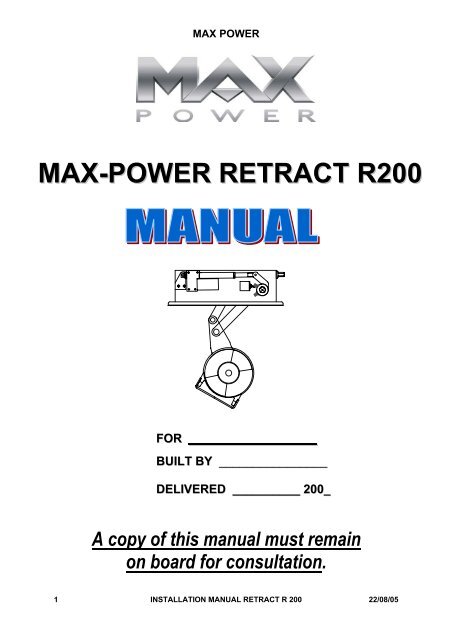
MAX-POWER RETRACT R200
MAX-POWER RETRACT R200
MAX-POWER RETRACT R200

You also want an ePaper? Increase the reach of your titles
YUMPU automatically turns print PDFs into web optimized ePapers that Google loves.
<strong>MAX</strong> <strong>POWER</strong><br />
<strong>MAX</strong>-<strong>POWER</strong> <strong>RETRACT</strong> <strong>R200</strong><br />
FOR ___________________<br />
BUILT BY ________________<br />
DELIVERED __________ 200_<br />
A copy of this manual must remain<br />
on board for consultation.<br />
1 INSTALLATION MANUAL <strong>RETRACT</strong> R 200 22/08/05
<strong>MAX</strong> <strong>POWER</strong><br />
I .<br />
A<br />
INTRODUCTION<br />
AFTER SALES SERVICE<br />
ADDRESS :<br />
<strong>MAX</strong> <strong>POWER</strong><br />
Parc d’Activité de la Siagne<br />
MANDELIEU TECHNOLOGY CENTER<br />
10, av. François Coli<br />
06210 MANDELIEU (CANNES) – France<br />
TEL : + 33 4 92 19 60 60<br />
FAX : + 33 4 92 19 60 61<br />
<strong>RETRACT</strong> SERIAL N°<br />
IMPORTANT GENERAL INFORMATION<br />
With a constant concern of improving our products, we reserve the right to make<br />
changes to this manual without prior notification.<br />
All statistics and explanations within this manual were believed to be correct at the<br />
time of printing.<br />
Each <strong>RETRACT</strong> installation requires a preliminary study of performance and<br />
feasibility.<br />
This study covers 4 distinct sub systems:<br />
1. The <strong>RETRACT</strong> thruster unit,<br />
2. Hydraulic equipment,<br />
3. Electrical equipment,<br />
4. Options<br />
CHECK LIST FOR THE PROJECT MANAGER<br />
It is very important to carefully read the entire manual before starting the installation.<br />
At the end of the manual, you will find a MAJOR POINT CHECKLIST when you are<br />
inspecting the work of your installers. All the points listed must be strictly respected<br />
for the proper and safe operation of the <strong>RETRACT</strong> system.<br />
The <strong>RETRACT</strong> should be installed by a professional specialising in this type of<br />
installation.<br />
Architects, construction shipyards and surveyors should be contacted before<br />
installation.<br />
All official bodies or classification experts should be contacted before the installation.<br />
2 INSTALLATION MANUAL <strong>RETRACT</strong> R 200 22/08/05
<strong>MAX</strong> <strong>POWER</strong><br />
All mechanical installation must apply with the conditions as laid down in the country<br />
of the boats registration.<br />
All electrical installation must apply with the conditions as laid down in the country of<br />
the boats registration origin.<br />
All hydraulic installation must apply with the conditions as laid down in the country of<br />
the boats registration origin.<br />
POSITIONING OF THE <strong>RETRACT</strong> UNIT<br />
IMPORTANT Correct positioning is essential for correct operation.<br />
The difference between the centre of gravity of the submerged surfaces and the<br />
centre of gravity of the surfaces exposed to side wind forces results in a rotational<br />
torque.<br />
One of the bow thruster’s primary functions is to neutralise this torque.<br />
Therefore the distance between the thruster and the yachts extremities must be as<br />
LONG as possible.<br />
See installation drawing<br />
The following considerations are essential when determining the position of the<br />
<strong>RETRACT</strong>.<br />
The top of the turbine must be 300 mm below the water line when fully extended.<br />
In other words the turbine should be at least one full diameter below the water line.<br />
The mounting-flange should be parallel with the bottom of the hull.<br />
The structural compatibility of the mounting base,<br />
The access needed for installation, and removal of unit,<br />
IMPORTANT make sure that there is enough room to allow for complete removal of<br />
the <strong>RETRACT</strong> unit, and room for the connection of the hydraulic piping, either by the<br />
direct coupling of the flexible hoses or by the use of metallic elbow connections.<br />
Sufficient access for all maintenance procedures must be allowed for.<br />
NOTE Always make sure that there is enough room for the manual override system.<br />
See drawing<br />
To install a <strong>RETRACT</strong> in the stern, make sure that the turbine flow is clear of all<br />
obstacles, or select the best possible compromise.<br />
3 INSTALLATION MANUAL <strong>RETRACT</strong> R 200 22/08/05
<strong>MAX</strong> <strong>POWER</strong><br />
INSTALLATION OF THE <strong>RETRACT</strong> UNIT<br />
CONSTRUCTION OF THE MOUNTING BASE<br />
<strong>MAX</strong> <strong>POWER</strong> can supply, as an option, a G.R.P. laminated mounting base, or an<br />
aluminium machined mounting-flange. These options allow you to save considerable<br />
installation time, and assure precise installation.<br />
The general method and materials used must be adapted to the particular hull<br />
material (laminated wood, GRP, sandwich, aluminium, or steel). Naval Architects,<br />
Classification Societies or engineering firms should be consulted.<br />
The thruster’s mechanical stresses are spread over the hull by the mounting base.<br />
Installation, which should be executed by welding or bonding to the hulls plating,<br />
normally reinforces the hull, the mounting base may be attached to frames and<br />
stringers as well.<br />
After the mounting base has been made and fitted the <strong>RETRACT</strong> should be<br />
temporarily secured on the flange to check its height its, centring, the accessibility of<br />
fittings and the ease of operation for manual override system.<br />
GRP HULLS<br />
The mounting base may be moulded into the hull during construction or<br />
prefabricated, and then laminated onto the hull later.<br />
METAL HULLS<br />
The mounting base may be constructed with the hull or prefabricated, and then<br />
welded onto the hull later.<br />
IMPORTANT In both cases, the top surface of the mounting base (or the flange)<br />
must be given particular attention and machined perfectly flat in order to accept the O<br />
ring seal of the <strong>RETRACT</strong> base flange and ensure perfect water tightness.<br />
The bolts fixing the <strong>RETRACT</strong> onto the mounting flange must be inserted from top to<br />
bottom. Provide sufficient access underneath the flange to allow for tightening the<br />
nuts.<br />
If the access is not possible, provide a special mounting flange with metric 10 mm<br />
studs or tapped holes.<br />
4 INSTALLATION MANUAL <strong>RETRACT</strong> R 200 22/08/05
<strong>MAX</strong> <strong>POWER</strong><br />
CONSTRUCTION OF HULL OPENING & CLOSING PLATE<br />
The required hull opening dimensions are L = 350 mm x W = 260 mm.<br />
The longitudinal centre line of the opening coincides with that of the mounting flange<br />
but the transversal centre line of the opening is offset by 27 mm to the rear with<br />
respect to the transversal centre line of the mounting flange.<br />
The opening is closed by a plate, which may be made from the cut out hull section, or<br />
specially fabricated.<br />
This closing plate should bear against a flexible seal fixed to a 30-mm wide rebate.<br />
While the hull opening closing plate is being made, the <strong>RETRACT</strong> must be<br />
temporarily secured on the mounting base flange to facilitate correct closing plate<br />
fabrication.<br />
The hull plate must be fixed to the supplied aluminium adjustable mounting (which<br />
has 4 elongated holes for initial adjustment).<br />
The gasket in the hulls rebate can be made either out off soft cellular neoprene<br />
rubber or moulded in soft SIKAFLEX (or a similar product) to form a flexible seal.<br />
Precaution must be taken to ensure that the flexible gasket does not glue the closing<br />
plate to the hull while drying .The plate must rest evenly, on the gasket, and with<br />
reasonable pressure.<br />
IMPORTANT To prevent marine growth inside the casing, it is essential that once the<br />
unit is raised, no light is allowed to enter. Therefore the closing plate gasket is<br />
essential and requires careful and permanent fixation.<br />
FINAL FITTING OF THE <strong>RETRACT</strong> UNIT TO THE MOUNTING BASE<br />
CAUTION To ensure absolute cleanliness, hydraulic lines and ports must remain<br />
plugged until connection to hydraulic system.<br />
Final installation on the mounting base must be made after thoroughly cleaning and<br />
then liberally coating both joining surfaces (case and base) with a good quality<br />
marine grease. This is so that the O-ring seal is compressed flat, evenly, smoothly<br />
and squarely when the bolts are tightened.<br />
Under no circumstances should the <strong>RETRACT</strong> be glued or bedded down with a<br />
marine type mastic/glue such as Sikaflex or other similar product.<br />
The flange bolt should be tightened sequentially and in successive passes until the<br />
two surfaces touch. If desired, a torque wrench can be used and the bolts can be<br />
tightened to a torque of 4,0 kg/M. The flange bolts should be metric size 10 mm of<br />
stainless steel, and should have a large stainless steel washer placed above a nylon<br />
washer. The nylon washers avoid stainless steel contact with the aluminium case.<br />
The nuts should be type NYLOCK.<br />
5 INSTALLATION MANUAL <strong>RETRACT</strong> R 200 22/08/05
<strong>MAX</strong> <strong>POWER</strong><br />
The 2 lifting lugs provided by <strong>MAX</strong> <strong>POWER</strong>, should be put in a small plastic bag,<br />
along with the hydraulic pipe plugs, for storage and future use by the ships crew or<br />
owner.<br />
FINAL ADJUSTING OF THE CLOSING PLATE (see drawing)<br />
Once the thruster is permanently bolted onto the mounting base and has<br />
been correctly tightened, reinstall the plate and check it’s adjustment.<br />
ELECTRIC RAM<br />
The final adjustment of the closing plate is as follows:<br />
Note: To extend and retract the electric ram, use a 24 V battery. Extend and retract<br />
by reversing the polarity. During the adjustment procedure, use a 5-amp fuse to<br />
protect the electric ram and its motor.<br />
1. Position the ‘up’ sensor so that the thruster can be fully retracted without<br />
mechanical interference. (see diagram Page 20)<br />
2. Position the ‘down’ sensor so that the thruster can be extended to it’s<br />
operational position. (see diagram Page 20)<br />
3. Lower and raise the turbine as necessary to adjust the closing plate, so that it<br />
fits evenly and squarely in its recess in the hull then tighten its fixation bolts.<br />
CAUTION: The closing plate must rest on the gasket evenly, with a slight pressure so<br />
that no upwards movement of the plate is possible even in heavy sea conditions<br />
when the hull is subjected to slamming forces.<br />
Care must also be taken to be sure that the Retract is not totally retracted as shown<br />
in fig 1 (Page 20) if this were to be the case damage might occur to the turbine.<br />
The final result should be as in Fig 2 (Page20) with flexible seal D slightly<br />
compressed. When final adjustment is achieved use locktite or a similar product on<br />
the sensor fixation bolts.<br />
6 INSTALLATION MANUAL <strong>RETRACT</strong> R 200 22/08/05
<strong>MAX</strong> <strong>POWER</strong><br />
TRANSMISSION LUBE OIL TANK INSTALLATION<br />
The transmission lub oil tank is no longer used on retract series units<br />
HYDRAULIC <strong>POWER</strong> SYSTEM INSTALLATION<br />
CAUTION: To ensure absolute cleanliness, hydraulic lines and ports must remain<br />
plugged until final connection.<br />
The hydraulic power equipment, such as the oil reservoir/filter, pump and directional<br />
valve, should be installed in compliance with the usual rules of accessibility to enable<br />
periodic checks and maintenance.<br />
All hydraulic high pressure power circuit piping must comply with high pressure<br />
standards (Flexible hose – HP SAE 100 R8 or R9), and have a diameter at least<br />
equal to that recommended in order to reduce head loss especially when the<br />
installation’s layout requires long hose lines. These hoses or pipes should preferably<br />
have 1/2″ interior diameter; No hose, pipe or fitting in the power circuit should ever<br />
have an interior diameter less than 3/8″. All power circuit piping must have a service<br />
pressure rating of at least 250 bar, with a rupture pressure rating of 1000 bar. Fittings<br />
must be of good quality and crimped as per manufacturers instructions, and pressure<br />
tested to at least 600 bar.<br />
All pipes and hoses must be clinically clean when connected to the circuit.<br />
The pump intake hose line (from the reservoir) must be of a quality that is not subject<br />
to pinching or crimping due either to vacuum, to an excessively small radius of<br />
curvature, or to variations of temperature.<br />
This hose or pipe should always be shorter than 2 meters and preferably have 1″<br />
interior diameter but not less than 3/4″ID<br />
CAUTION: the oil tank must gravity feed to the pump, it must also be above the water<br />
line.<br />
The directional valve must be fitted as close as is convenient to the <strong>RETRACT</strong> unit,<br />
in order to verify the hydraulic gauge. All piping connected to the <strong>RETRACT</strong> unit<br />
must be of a non-conductive type (not metal braided hose) and at least 50 mm<br />
long.<br />
The thrusters’ motor case drain must return directly to the top of the tank. With<br />
no filters check valves or other drain lines connected to it. Backpressure on the RD<br />
(drain line) will cause damage to the hydraulic motor.<br />
7 INSTALLATION MANUAL <strong>RETRACT</strong> R 200 22/08/05
Power Requirements<br />
<strong>MAX</strong> <strong>POWER</strong><br />
ELECTRICAL SYSTEM INSTALLATION<br />
The control system of the <strong>RETRACT</strong> requires 15 amps.<br />
NOTE: The voltage of the power system is determined by the vessels battery system<br />
and the Electro-pump will have been ordered to suit.<br />
For electro pump models the power systems cable sections must follow these rules<br />
Length (L) = positive line + negative line. Example: Distance between pump and<br />
batteries = 1,50 m, then L = 3 m. (See Drawing)<br />
<strong>R200</strong>/6 <strong>R200</strong>/8<br />
L = 1 m = 70 mm² L = 1 m = 95 mm²<br />
L = 3 m = 95 mm² L = 3 m = 120 mm²<br />
L = 5 m = 120 mm² L = 5 m = 150 mm²<br />
L = 10 m = 150 mm² L = 10 m = 190 mm²<br />
For long cable runs it can be easier to use 2x a smaller section e.g.;<br />
For 95mm² use 2x50mm²<br />
Battery requirements are for starting or High CCA type and are as follows<br />
<strong>R200</strong><br />
Type of Batteries Exide, Maxxima 900<br />
Number of Batteries 4 to 6<br />
Type of Connection<br />
Series/Parallel<br />
<strong>R200</strong> Electropump Battery Requrements<br />
+<br />
12 V<br />
800 CCA<br />
50 Ah<br />
+<br />
12 V<br />
800 CCA<br />
50 Ah<br />
Pos. ( + )<br />
To 24 V Electropump<br />
Series/Parallel<br />
Pos. ( + )<br />
+<br />
12 V<br />
800 CCA<br />
50 Ah<br />
-<br />
+<br />
12 V<br />
800 CCA<br />
50 Ah<br />
-<br />
-<br />
+<br />
12 V<br />
800 CCA<br />
50 Ah<br />
-<br />
+<br />
12 V<br />
800 CCA<br />
50 Ah<br />
Neg. ( - )<br />
OR<br />
24 V<br />
2400 CCA<br />
150 Ah<br />
Series/Parallel<br />
+<br />
+<br />
12 V<br />
800 CCA<br />
50 Ah<br />
12 V<br />
800 CCA<br />
50 Ah<br />
-<br />
-<br />
+<br />
+<br />
12 V<br />
800 CCA<br />
50 Ah<br />
12 V<br />
800 CCA<br />
50 Ah<br />
-<br />
-<br />
-<br />
-<br />
Minimum Battery<br />
Bank Size<br />
Neg. ( - )<br />
Ideal Battery<br />
Bank Size<br />
Note the lower the cold cranking capacity of the batteries used the larger the battery<br />
bank will need to be.<br />
A battery is considered to be high CCA as from 650CCA for each 60Ah battery<br />
8 INSTALLATION MANUAL <strong>RETRACT</strong> R 200 22/08/05
<strong>MAX</strong> <strong>POWER</strong><br />
1 – Wiring Installation<br />
Control system wiring: All wires should be carefully labelled to reduce the<br />
chance of Error and simplify checking and troubleshooting.<br />
All wires ends for terminals should be tinned before crimping or inserting into<br />
terminal blocks.<br />
Power system wiring: The electrical cables should be of the specified<br />
dimensions and should be connected directly from the batteries to the fuse(s),<br />
power relay (s) and finally to the Electro-pump. The only other equipment that<br />
may be added is a battery cut-off switch - if desired. No other equipment<br />
should be connected to the <strong>RETRACT</strong>’S electrical wiring.<br />
The Electro pump is fitted with a high temperature alarm switch. This switch<br />
(N O) is fitted as standard and can be used either for a second buzzer or for<br />
complete shut down of the unit (via a relay 0.5 AMP max). These options are<br />
to be wired in by the shipyard.<br />
Note: the Electro-pump does not have a specific polarity.<br />
IMPORTANT: The efficiency of the <strong>RETRACT</strong> depends on the quality of the<br />
electrical installation.<br />
CAUTION the Electro-pump must not be installed in a small sealed space. Make<br />
sure that there is sufficient supply of cooling air available.<br />
NOTE: Never bond or ground the <strong>RETRACT</strong> to other equipment on board. All wiring<br />
must be insulated from ground and should be installed in compliance with acceptable<br />
standards that require all junctions to be in waterproof boxes equipped with glands.<br />
All wiring should be kept outside of bilges and other habitually wet areas.<br />
2 - Optional wiring of extra power relays (negative)<br />
→<br />
→<br />
Bipolar electricity option. An extra relay is added on the negative battery wire<br />
and is commanded with n° 7 & 8 (same as the positive relay).<br />
Adjusting the position actuators (see diagram)<br />
Adjust the position actuator UP (H) and the position actuator DOWN (B). This is done<br />
by loosening the stainless steel ring and sliding the 2 actuators so that the switch can<br />
be engaged in the 2 positions. The black wire must not be removed.<br />
9 INSTALLATION MANUAL <strong>RETRACT</strong> R 200 22/08/05
<strong>MAX</strong> <strong>POWER</strong><br />
CHECKS, TESTS & ADJUSTMENTS<br />
BEFORE LAUNCHING<br />
IMPORTANT: Before the launch, verify that the <strong>RETRACT</strong> unit inspection top plate<br />
has been replaced (if it was removed during installation) and that the entire lower<br />
flange bolts have been tightened. Torque for all these bolts to 1,5 kg/m.<br />
Filling the hydraulic circuit.<br />
<strong>MAX</strong> <strong>POWER</strong> recommends the use of ISO GRADE 15 to 32 hydraulic oils for the<br />
power circuit. This oil has already been used by Max Power during the run in tests<br />
and consequently the <strong>RETRACT</strong> motor and piping are already filled with such.<br />
CAUTION: Biodegradable and mineral (commonly used) oils are non-compatible and<br />
should not be mixed or used together. Mixing them will deteriorate certain hydraulic<br />
elements. If you intend to use a biodegradable oil, thoroughly flush the existing<br />
mineral oil from the <strong>RETRACT</strong> unit first with the appropriate oil.<br />
Before carrying out the following tests we recommend disconnecting the supply to<br />
the EHP and DCV in the control box.<br />
→<br />
→<br />
→<br />
Check all fittings for tightness and leaks.<br />
The transmission is already filled with oil at the time of delivery.<br />
Check UP / DOWN operation.<br />
Note: if the up and down system functions the wrong way round, reverse the wires<br />
on the ram.<br />
When all the tests have been completed, reconnect the supply to the EHP and DCV<br />
in the control box.<br />
AFTER LAUNCHING<br />
→<br />
→<br />
→<br />
Check for water leaks.<br />
Switch on the system power at the breaker and repeat the UP / DOWN tests.<br />
Execute a few short left and right manoeuvres to fill the circuits and thereby<br />
purge the system of all air. After each manoeuvre, check and fill if necessary,<br />
the hydraulic tank. Repeat until the level remains stable.<br />
Do not allow the Electro-pump to run dry.<br />
→<br />
→<br />
Check the thrust direction:<br />
With the Joystick to the left (port), the vessel should move to port and<br />
conversely. If the direction is not correct, inverse to connectors on the<br />
hydraulic distributor.<br />
10 INSTALLATION MANUAL <strong>RETRACT</strong> R 200 22/08/05
<strong>MAX</strong> <strong>POWER</strong><br />
The left and right thrust tests must be made under normal conditions of use. In<br />
other words that means that the batteries are fully charged and the main<br />
engine alternator is running and the batteries are being correctly recharged. (If<br />
Electro pump)<br />
The relief valve has been pre-set in the factory and must not be altered.<br />
The pressure can be read on the pressure gauge (10). Important: Close pressure<br />
valves after checks.<br />
The pressure reading should correspond to the following chart:<br />
Model <strong>R200</strong>/6 200 to 240 bars.<br />
Model <strong>R200</strong>/8 230 to 250 bars.<br />
Variations are possible depending upon the installation.<br />
WARRANTY REQUIREMENT<br />
IMPORTANT: All Test readings must be filled out on the form provided and sent to<br />
Max Power by fax no later than one week after the water tests have been completed<br />
so that the Max Power standard warranty is correctly validated. This form is attached<br />
at the end of this manual.<br />
11 INSTALLATION MANUAL <strong>RETRACT</strong> R 200 22/08/05
<strong>MAX</strong> <strong>POWER</strong><br />
OPERATION AND USE<br />
1) General operation<br />
CONTROL PANEL AND THRUSTER CONTROL BOX FUNCTIONS:<br />
"On/Off" Push-button:<br />
Black with Green<br />
"On" LED.<br />
Joystick<br />
"Up" Push-button:<br />
Green with Green<br />
"Up" LED.<br />
"Down" Push-button:<br />
Red with Green<br />
"Down" LED.<br />
Control Panel:<br />
To switch "ON" or "OFF" push down<br />
the black push-button, while pushing<br />
joystick to the right for one second.<br />
To "Lower" or "Raise" press and hold<br />
the "Down" or "Up" pushbutton until<br />
buzzer in control panel double beeps,<br />
which indicates unit has reached fully<br />
down or fully up position..<br />
Switching System "On" or "Off":<br />
a) To switch the thruster "ON" or "OFF" follow the instructions on the diagram<br />
above.<br />
b) When switched "ON" the unit will double beep and the LED's in the black and<br />
green push buttons will light up.<br />
c) When switched "OFF" the unit will double beep and the LED's will go out. It's<br />
only possible to switch off the unit with thruster in the fully up position.<br />
"Lowering" & "Raising" Thruster Unit:<br />
a) Once the unit has been switched on, as described above, press and hold the<br />
"Down" pushbutton to lower. The buzzer will start beeping and the "Down" LED<br />
will start to flash as soon as the thruster leaves the up position.<br />
b) If "Down" or "Up" pushbutton is released before "Down" or "Up" position is<br />
detected, the buzzer will start to beep (short) once every ½ second and both "Up"<br />
& "Down» LED’s will start flashing.<br />
c) When thruster is detected to be fully down, the "Down" LED comes on and the<br />
buzzer double beeps to indicate that thruster is completely down and ready to<br />
thrust.<br />
d) As long as the thruster is in the "Down" position the buzzer will beep (short) once<br />
every three seconds, to indicate that thruster is still in the down position.<br />
e) To raise thruster, press and hold the "Up" pushbutton. When thruster is detected<br />
to be fully up the "Up" LED comes on and the buzzer double beeps to indicate<br />
that thruster is completely up and ready to be switched off.<br />
12 INSTALLATION MANUAL <strong>RETRACT</strong> R 200 22/08/05
<strong>MAX</strong> <strong>POWER</strong><br />
Thrusting "Left" or "Right":<br />
a) Use joystick to thrust either left or right.<br />
b) Please note that it is only possible to thrust left or right when thruster is detected<br />
to be fully down.<br />
c) The thruster controller provides a time delay between left and right thrust in<br />
order to avoid rapid direction changes, but no delay when thrusting to same<br />
side.<br />
NOTE: Right and left thrust signals will not be sent until the turbine is in a fully extended<br />
position with the red light illuminated and the buzzer on.<br />
Overheat Alarm & Shut-Down:<br />
( a ) If the thruster motor overheats the buzzer will start beeping and the "On" L.E.D. will<br />
flashes with one-second intervals until<br />
the motor has cooled down.<br />
( b ) During this overheat condition one has a total of ten seconds of actual use (left &<br />
right thrust) of the thruster, after which it<br />
will not be possible to continue thrusting in either direction.<br />
( c ) The thruster must then be raised by pushing the "Up" push button. Once thruster is<br />
detected to be fully up the system will<br />
switch off automatically.<br />
( d ) After this overheat shut down it will not be possible to switch "On" the system<br />
again until the thruster motor has cooled down.<br />
General:<br />
( a ) If the thruster unit is in the "Up" position and has not been used for a period of ten<br />
minutes the unit will automatically switch off.<br />
Before automatically switching off the unit will warn you by beeping once followed<br />
by a second beep a few seconds later, after<br />
which the unit switch off.<br />
( b ) In order to isolate the power circuit of the thruster motor each time the control<br />
circuit is switched off one would need to install<br />
an electric battery isolator, as advised by Max Power (see "Wiring Diagram" in the<br />
back of this manual for more detail).<br />
( c ) When electronic control box is powered up and "Up" position detector is not<br />
detected, the "Up" L.E.D. will start flashing and<br />
the buzzer will beep once every second.<br />
The "Up" push-button should then be pressed until unit is detected to be fully "Up".<br />
After which the buzzer will beep twice and<br />
the system will be switched off automatically.<br />
NEVER LEAVE THE <strong>RETRACT</strong> DOWN WHEN NOT IN USE<br />
13 INSTALLATION MANUAL <strong>RETRACT</strong> R 200 22/08/05
<strong>MAX</strong> <strong>POWER</strong><br />
LIMITATIONS:<br />
→<br />
→<br />
→<br />
The <strong>RETRACT</strong> must be in the up position (retracted) when sailing. The<br />
<strong>RETRACT</strong> is designed to be used in harbour when manoeuvring at low speed<br />
and must not be in the down position for speeds above 3 knots.<br />
Do not use <strong>RETRACT</strong> in water temperatures below – 5 ° in salt water.<br />
Estimated maximum overall and intermittent operating times for all the <strong>R200</strong><br />
models (before heat accumulation produces too high a temperature in the<br />
Electro-pump).<br />
Do not use the <strong>RETRACT</strong> in a bathing zone.<br />
Continuous operation: 2 min (class S2).<br />
The Electro-pump motor should have approximately a 30 minutes rest period<br />
after maximum use. These figures are conservative and for ambient<br />
temperatures of 20 degrees C. they are also highly dependent upon the fresh<br />
air ventilation of the Electro-pump motor.<br />
For longer service, extra air-cooling of the Electro-pump unit can be installed,<br />
such as a forced air-ventilating fan. Also increased battery capacity may need<br />
to be provided.<br />
The thruster should always be used in normal manoeuvring conditions with<br />
charged batteries and with the main engine’s alternator running and charging<br />
the batteries, etc…<br />
MAINTENANCE OF THE <strong>RETRACT</strong><br />
Regular checks:<br />
→<br />
→<br />
→<br />
→<br />
Lower and raise several times every month<br />
Transmission lubricating oil reservoir level.<br />
Hydraulic power oil reservoir level.<br />
Hydraulic hoses for chaffing and leaks.<br />
Control panels, like all external equipment, should be protected from the sun and<br />
weather. Clean with a soft cloth and mild detergent solution.<br />
Yearly checks boat ashore:<br />
1. Clean the turbine, gearbox and the propellers with a sponge and detergent<br />
soap. It is also advisable to remove the top cover plate and clean the interior of<br />
the case and rinse well the articulated joints.<br />
IMPORTANT: If the vessel is to remain out of the water for some time, for example:<br />
dry storage for the winter, the top cover plate must be removed and the <strong>RETRACT</strong><br />
mechanism must be thoroughly rinsed with fresh water, especially the articulated<br />
joints. Do not operate below 0° C.<br />
2. Replace all anodes<br />
14 INSTALLATION MANUAL <strong>RETRACT</strong> R 200 22/08/05
<strong>MAX</strong> <strong>POWER</strong><br />
3. Remove the propellers regularly (use a Hub extractor on the special flange<br />
provided) Apply marine type grease to shafts<br />
4. Check and replace if necessary the two-drive leg oil seals. (Bronze drive legs<br />
only)<br />
Note: Although identical, the propellers should always be re-installed on the same<br />
side as before.<br />
5. Inspect and repair the hull closing plate gasket for deterioration or missing<br />
pieces.<br />
Check and tighten if necessary, the plate fixation bolts.<br />
6. Apply antifouling paint to the closing plate on the outside, on the edges and if<br />
desired to the plates inner surface. If you find growth on the unit, this is<br />
because your closing plate gasket allows light to enter the enclosure.<br />
CAUTION: Do not use antifouling or other copper based paints on the <strong>RETRACT</strong><br />
turbine.<br />
7. The transmission oil must be changed each year. This is done by opening the<br />
vent valve on the rearward side of the retract arm (above the propellers),<br />
remove the lower bleed screw (6mm Allen bolt, underneath between the<br />
propellers), then allow the oil to drain, refill via the lower bleed screw using<br />
75W90 gearbox oil, when full, close the vent valve and replace the lower bleed<br />
screw.<br />
Never let the oil level in the lub tank descend below the level of the ships<br />
waterline.<br />
8. Check the entire hydraulic system hoses and connections for possible chaffing<br />
and leaks.<br />
9. Every two years drain the entire hydraulic oil system. Clean and replace filters.<br />
10. Check all bolts for tightness especially on the under water unit.<br />
5 YEARS<br />
Complete removal of unit and return to factory.<br />
Replacement of all under water flexible hoses.<br />
Complete overhaul of the unit including paint, anti corrosion treatment, replacement<br />
of bearings, bushes, service/paint of hydraulic motor pressure tests etc.<br />
Service of complete hydraulic oil system including pump, distributor, etc.<br />
Replace Power relays where necessary.<br />
15 INSTALLATION MANUAL <strong>RETRACT</strong> R 200 22/08/05
<strong>MAX</strong> <strong>POWER</strong><br />
PROJECT MANAGER’S<br />
TEST RESULTS FORM<br />
To be filled in and<br />
faxed to <strong>MAX</strong> <strong>POWER</strong><br />
16 INSTALLATION MANUAL <strong>RETRACT</strong> R 200 22/08/05
<strong>MAX</strong> <strong>POWER</strong><br />
TEST RESULT FORM (part 1)<br />
This form must be filled in and faxed to <strong>MAX</strong> <strong>POWER</strong> within a week after launching<br />
so that the <strong>MAX</strong> <strong>POWER</strong> standard warranty is validated.<br />
<strong>MAX</strong> <strong>POWER</strong><br />
10 allée François Coli<br />
PARC d’ACTIVITE DE LA SIAGNE<br />
06210 MANDELIEU – France<br />
Tel : (33) 4 92 19 60 60<br />
Fax : (33) 4 92 19 60 61<br />
From :<br />
………………………………<br />
………………………………<br />
………………………………<br />
………………………………<br />
………………………………<br />
………………………………<br />
………………………………<br />
Date: …………………………<br />
REFERENCE: S _ _ .R20 _ . _ _ _ _<br />
→<br />
→<br />
→<br />
→<br />
→<br />
Shipyard that installed the <strong>RETRACT</strong>:<br />
………………………………………………<br />
Name of the Project Manager:<br />
………………………………………………………..<br />
Name of the Vessel: …………………………………………………………………..<br />
Type & Make of the Vessel:<br />
…………………………………………………………..<br />
Date of launching:<br />
……………………………………………………………………...<br />
Please answer by YES or NO the following questions concerning the installation:<br />
1 Is the <strong>RETRACT</strong> mounted parallel with the bottom of the hull ?<br />
2 Is there enough room for general maintenance of the <strong>RETRACT</strong> and its auxiliary<br />
equipment?<br />
3 Does the closing plate rest on a gasket?<br />
4 Is the adjustment of the closing plate done in such a way that no light is allowed to<br />
enter?<br />
5 Are the anodes correctly fitted to the closing plate supports?<br />
6 Is the lub oil reservoir mounted at a minimum of 1000 mm (39″) above the<br />
waterline?<br />
7 Is The <strong>RETRACT</strong> glued to the mounting base?<br />
8 Does the Electro pump have adequate cooling and is the oil reservoir mounted<br />
above it?<br />
9 Are the limit switches correctly adjusted?<br />
10 Are all electrical wires numbered at each end and with their terminals tinned?<br />
YES<br />
NO<br />
17 INSTALLATION MANUAL <strong>RETRACT</strong> R 200 22/08/05
<strong>MAX</strong> <strong>POWER</strong><br />
TEST RESULT FORM (part 2)<br />
When all the tests have been completed as per the manual, please record the<br />
following measurements where applicable.<br />
With the engine(s) running, thruster in the down position, but not running:<br />
1. Record the charging amps of the alternator(s) * …………………<br />
Amps<br />
2. Record the voltage at the remote control box: ………………… Volts<br />
3. Record the voltage at the electric ram ………………… Volts<br />
3. Record the voltage at the battery terminals: ………………… Volts<br />
With the engine(s) running and the thruster running (either direction) :<br />
1. Record the charging amps of the alternator(s) * : ………… Amps<br />
2. Record the voltage at the remote control box : ………………… Volts<br />
3. Record the voltage at the battery terminals* : ………………… Volts<br />
4. Record the voltage at the electropump motor* : ………… Volts<br />
5. Record the amperage at the electropump motor* : ………… Amps<br />
6. Record the hydraulic pressure : ………………… Bars<br />
: only when using the Electro-hydraulic unit as drive<br />
DATE OF TESTS: ………………….<br />
LOCATION: ………………...<br />
PERSON RESPONSIBLE: ……………………………..<br />
SIGNATURE:<br />
18 INSTALLATION MANUAL <strong>RETRACT</strong> R 200 22/08/05
<strong>MAX</strong> <strong>POWER</strong><br />
A minimum immersion depth of one full turbine diameter should<br />
be respected and the thrusters should be as far forward or<br />
aft as possible.<br />
The unit must be paralell with the botom of the hull<br />
As long as possible<br />
WL<br />
3RD ANGLE<br />
PROJECTION<br />
REVISION<br />
PART NO.<br />
UNLESS<br />
OTHERWISE<br />
SPECIFIED<br />
TITLE<br />
<strong>R200</strong> instalation<br />
REVISION PART NO.<br />
CADD<br />
SCALE REF.<br />
MATERIAL<br />
1:*<br />
Max Power<br />
DRAWN CHECK<br />
RELEASE<br />
HEAT TREAT & FINISH<br />
03/05/01 DATE<br />
DATE DATE<br />
<strong>POWER</strong><br />
Turning center<br />
19 INSTALLATION MANUAL <strong>RETRACT</strong> R 200 22/08/05
<strong>MAX</strong> <strong>POWER</strong><br />
62<br />
190<br />
250<br />
220<br />
Bow<br />
Allow 120<br />
500<br />
Bow<br />
The Thruster should be mounted<br />
paralell with the bottom of the hull<br />
Mounting base as supplied by <strong>MAX</strong> <strong>POWER</strong><br />
Hull parts manufactured by ship yard<br />
Principal dimensions<br />
Optional flotation foam to reduce loss of buoyancy<br />
Retract Thruster<br />
Construction point ( Never changes no matter the hull shape )<br />
Flexible water seals<br />
324<br />
165<br />
375<br />
210<br />
120<br />
220<br />
A composite flat Hull<br />
A composite deep V hull<br />
Do not build from these drawings , use those supplied with the unit .<br />
<strong>RETRACT</strong> <strong>R200</strong> PRINCIPAL DIMENSIONS<br />
25/4/01<br />
YT Turbo CAD<br />
20 INSTALLATION MANUAL <strong>RETRACT</strong> R 200 22/08/05
<strong>MAX</strong> <strong>POWER</strong><br />
PART NO.<br />
REVISION<br />
3RD ANGLE<br />
PROJECTION<br />
Caution this situation would<br />
cause damage to the turbine while<br />
at sea .<br />
These Bolts must be securely tightened<br />
using a mechanical glue (Lock tight).<br />
The flexible seal should be installed here.<br />
This gap is essential it should be<br />
of at least 5mm<br />
Gap<br />
REVISION PART NO.<br />
<strong>R200</strong> instalation<br />
TITLE<br />
UNLESS<br />
OTHERWISE<br />
SPECIFIED<br />
CADD<br />
SCALE REF.<br />
MATERIAL<br />
Max Power<br />
1:*<br />
HEAT TREAT & FINISH<br />
RELEASE<br />
DRAWN CHECK<br />
03/05/01 03/05/01 03/05/01<br />
DATE DATE DATE<br />
<strong>POWER</strong><br />
21 INSTALLATION MANUAL <strong>RETRACT</strong> R 200 22/08/05
<strong>MAX</strong> <strong>POWER</strong><br />
Ø1 mm<br />
Fixing Screws<br />
Drilling<br />
Template<br />
Ø52 mm<br />
(2 in.)<br />
BLACK Push-button<br />
with Green LED<br />
Base Unit<br />
Ø52 mm<br />
(2 in.)<br />
Joystick<br />
GREEN Push-button<br />
with Green LED<br />
Rubber Seal<br />
RED Push-button<br />
with Green LED.<br />
Clip-on Cover<br />
Rubber<br />
Joystick<br />
Cover<br />
DIAGRAM: 1 DIAGRAM: 2<br />
INSTALLATION GUIDELINES<br />
Diagram: 1<br />
1.1) Stick drilling template in desired mounting position.<br />
1.2) Drill the two 52 mm diameter holes using a holesaw.<br />
1.3) Place panel in holes and mark the 6 fixing holes.<br />
1.4) Remove panel and drill the six 1 mm diameter fixing holes.<br />
Diagram: 2<br />
2.1) Make sure that rubber seal is placed on the base column.<br />
2.2) Wire and/or plug unit to the control circuit.<br />
2.3) Position base so that the joystick is to the top and the<br />
"Red" button to the bottom.<br />
2.4) Fix base unit with the six fixing screws as supplied with unit.<br />
Diagram: 3<br />
3.1) Only when totally finished and satisfied with wiring and<br />
positioning of the unit, clip-on the face panel/cover.<br />
3.2) Leave rubber joystick cover inserted to clip-on cover<br />
when clipping cover into place and push down well<br />
once in place.<br />
(c)<br />
DIAGRAM: 3<br />
Diagram: 4<br />
4.1) To remove the clip-on cover slide a flat headed screwdriver,<br />
with 6 - 7 mm wide tip, between the clip-on cover and the<br />
dashboard at position (a), (b) and then (c) and twist the tip<br />
slightly. Push in the tip of the screwdriver at least 3 to 4 mm<br />
before twisting it.<br />
6 to 7 mm<br />
3 to 4 mm<br />
(b)<br />
Push & Twist<br />
(a)<br />
Push & Twist<br />
DIAGRAM: 4<br />
22 INSTALLATION MANUAL <strong>RETRACT</strong> R 200 22/08/05
Motor<br />
Heat<br />
-<br />
-<br />
-<br />
-<br />
-<br />
-<br />
-<br />
-<br />
<strong>MAX</strong> <strong>POWER</strong><br />
12<br />
Control cable as supplied with unit.<br />
Yachts Main DC Equipment<br />
Breaker Board<br />
OFF OFF OFF OFF OFF OFF OFF OFF<br />
ON ON ON ON ON ON ON ON<br />
+<br />
+<br />
+<br />
+<br />
+<br />
+<br />
+<br />
+<br />
Control Supply:<br />
To be connected<br />
to seperate battery<br />
bank (advised ) or<br />
thruster battery bank.<br />
-<br />
11<br />
+<br />
Fuse ( 15 A )<br />
2 x 2.5 mm²<br />
(Depending on cable lenght - I max = 15A )<br />
1 - ve<br />
2 +ve<br />
TITLE REVISION PART NO.<br />
A<br />
<strong>R200</strong>: Wiring Diagram<br />
CADD<br />
SCALE MATERIAL<br />
REF.<br />
Max Power<br />
DRAWN CHECK RELEASE HEAT TREAT & FINISH<br />
JC<br />
DATE DATE<br />
DATE<br />
18/02/05<br />
<strong>POWER</strong><br />
Black<br />
Purple<br />
Brown<br />
Blue<br />
Red<br />
White<br />
Orange ( Raise )<br />
Grey ( Lower )<br />
+ve Out<br />
On/Off<br />
Left<br />
Right<br />
Up<br />
Down<br />
On LED<br />
Up LED<br />
10<br />
Raise/Lower<br />
Control Panel Limit Switches<br />
1 - Thruster Battery Bank<br />
2 - Fuse & Fuse Holder<br />
3 - Manual Battery Isolator<br />
4 - Electric Battery Isolator<br />
5 - Power Relay / Electro Clutch<br />
6 - EHP with N/O N/O Heat Sensor<br />
7 - Directional Control Valve<br />
8 - Electric Up/Down RAM<br />
9 - Proximity Switch<br />
10 - Electronic Control Card<br />
11 - Double Pole Isolator<br />
12 - Control Panel<br />
Yellow<br />
Yellow<br />
Black<br />
Brown<br />
Blue<br />
Black<br />
3 x 1 mm²<br />
(Depending on cable lenght - I max = 2 A )<br />
Grey<br />
White<br />
Yellow<br />
Yellow<br />
Brown<br />
Black<br />
7<br />
Red ( Up )<br />
Blue<br />
Black<br />
Black<br />
Red ( Up )<br />
Black ( Com. )<br />
Green ( Down )<br />
Green<br />
Yellow<br />
Black ( Com. )<br />
Green ( Down )<br />
Yellow<br />
Yellow<br />
Down LED<br />
Alarm<br />
Up<br />
Com<br />
Down<br />
Com<br />
Heat<br />
Com<br />
<strong>MAX</strong> <strong>POWER</strong><br />
Controller<br />
Type MP - VIP<br />
Grey<br />
White<br />
Yellow<br />
Yellow<br />
Brown<br />
Blue<br />
Black<br />
9<br />
Red<br />
Black<br />
Green<br />
8<br />
Isolator Thruster<br />
Black<br />
Aux<br />
Neg.<br />
Left<br />
Neg.<br />
Right<br />
Iso<br />
Neg.<br />
Grey<br />
Blue<br />
Black<br />
White<br />
Brown<br />
Black<br />
Grey<br />
White<br />
Yellow<br />
Yellow<br />
Brown<br />
Blue<br />
Black<br />
Yellow<br />
Yellow<br />
Brown<br />
Blue<br />
Black<br />
3 x 1 mm²<br />
(Depending on cable lenght - I max = 7 A )<br />
2 x 2.5 mm²<br />
(Depending on cable lenght - I max = 15A )<br />
Black<br />
Grey<br />
White<br />
6<br />
5<br />
4<br />
3<br />
2<br />
12/24V<br />
High Power Starting<br />
Type Battery Bank<br />
1<br />
Thrusters are delivered with<br />
up/down motors pre-wired.<br />
For both 12 & 24V models the<br />
up/down motors are wired in<br />
parallel<br />
White<br />
Black<br />
Grey<br />
Black<br />
23 INSTALLATION MANUAL <strong>RETRACT</strong> R 200 22/08/05
<strong>MAX</strong> <strong>POWER</strong><br />
Control Panel<br />
Cable<br />
Connector<br />
Control Panel<br />
Cable<br />
Connector<br />
Cable<br />
Connector<br />
Cable<br />
Connector<br />
Connection of Additional Control Panels:<br />
White<br />
Red<br />
Brown<br />
Blue<br />
Black<br />
Yellow<br />
Orange (Raise)<br />
Purple<br />
Grey (Lower)<br />
Green<br />
Green<br />
Grey (Lower)<br />
Purple<br />
Orange (Raise)<br />
Yellow<br />
Black<br />
Blue<br />
Brown<br />
Red<br />
White<br />
Control cable<br />
as supplied<br />
with unit.<br />
White<br />
Red<br />
Brown<br />
Blue<br />
Black<br />
Yellow<br />
Orange (Raise)<br />
Purple<br />
Grey (Lower)<br />
From <strong>R200</strong><br />
Electronic<br />
Control Box<br />
White<br />
Red<br />
Brown<br />
Blue<br />
Black<br />
Yellow<br />
Orange (Raise)<br />
Purple<br />
Grey (Lower)<br />
Green<br />
Green<br />
24 INSTALLATION MANUAL <strong>RETRACT</strong> R 200 22/08/05
<strong>MAX</strong> <strong>POWER</strong><br />
<strong>R200</strong> THRUSTER: ELECTRONIC CONTROL BOX CONNECTIONS:<br />
Control<br />
Circuit<br />
Supply<br />
(Note 1)<br />
+<br />
-<br />
Black<br />
Red<br />
1 - ve<br />
2 +ve<br />
Fuse ( 15 A )<br />
To Electric<br />
"Up/Down" RAM<br />
Raise/Lower<br />
Control Panel<br />
+ve Out<br />
On/Off<br />
Left<br />
Right<br />
Up<br />
Down<br />
On LED<br />
Up LED<br />
Down LED<br />
Alarm<br />
Red<br />
White<br />
Brown<br />
Blue<br />
Orange ( Raise )<br />
Orange ( Lower )<br />
Black<br />
Purple<br />
Green<br />
Yellow<br />
From<br />
Control<br />
Panel<br />
Limit Switches<br />
25 INSTALLATION MANUAL <strong>RETRACT</strong> R 200 22/08/05<br />
To Power Relay<br />
or Electro Clutch<br />
Black<br />
White<br />
Aux<br />
Neg.<br />
<strong>MAX</strong> <strong>POWER</strong><br />
Controller<br />
Up<br />
Com<br />
Red ( Up )<br />
Black ( Com. )<br />
Brown<br />
Black<br />
Blue<br />
Left<br />
Neg.<br />
Right<br />
To Proximity Switch<br />
To Directional<br />
Control Valve<br />
Isolator Thruster<br />
Type MP - VIP<br />
Down<br />
Com<br />
Green<br />
Motor<br />
Heat<br />
Heat<br />
Com<br />
Yellow<br />
Yellow<br />
To N/O Heat Sensor<br />
on Electro Hydr. Pump<br />
To Electric<br />
Battery Isolator<br />
Grey<br />
Black<br />
Iso<br />
Neg.<br />
NOTES:<br />
1. The installer must protect the positive supply cable by means of a fuse (slow blow) as indicated.<br />
The size of these supply wires (min. 2,5mm² with Imax = 15 A) depends on the length of the cable run and<br />
the voltage drop in these cables should not exceed 5% of the nominal battery voltage.<br />
2. Install an electric isolator/switch, in the supply of the thruster control box, on the boats main electrical switch board, marked "Bow Thruster".<br />
This breaker or switch should ideally be supplied from a source independent to that used for the thruster. See "Wiring Diagram for more detail.
<strong>MAX</strong> <strong>POWER</strong><br />
REVISION<br />
PART NO.<br />
TURBINE IN THE UP POSITION<br />
TURBINE IN THE DOWN POSITION<br />
3RD ANGLE<br />
PROJECTION<br />
With the turbine in the up position adjust<br />
the position actuator so that it has only<br />
just triped the switched .Use a volt meter<br />
to do this operation.<br />
With the turbine in the down position adjust<br />
the position actuator so that it has only<br />
just triped the switched .Use a volt meter<br />
to do this operation.<br />
With the ram removed the turbine<br />
can be raised using a 24mm wrench<br />
TITLE<br />
<strong>R200</strong> instalation<br />
REVISION PART NO.<br />
CADD<br />
SCALE REF.<br />
MATERIAL<br />
1:*<br />
Max Power<br />
DRAWN CHECK<br />
RELEASE<br />
HEAT TREAT & FINISH<br />
03/05/01 18/02/05 DATE<br />
DATE DATE<br />
<strong>POWER</strong><br />
UNLESS<br />
OTHERWISE<br />
SPECIFIED<br />
Green ( Down )<br />
Red ( Up )<br />
Black ( Com. )<br />
To Electronic Control Card<br />
To Electronic Control Card<br />
Green ( Down )<br />
Red ( Up )<br />
Black ( Com. )<br />
To Electronic Control Card<br />
To Electronic Control Card<br />
26 INSTALLATION MANUAL <strong>RETRACT</strong> R 200 22/08/05
<strong>MAX</strong> <strong>POWER</strong><br />
PART NO.<br />
REVISION<br />
Power<br />
Relay<br />
<strong>POWER</strong> SYSTEM CABLING:<br />
Electric<br />
Battery<br />
Isolator<br />
Manual<br />
Battery<br />
Isolator<br />
Power Fuse<br />
&<br />
Fuse Holder<br />
3RD ANGLE<br />
PROJECTION<br />
A<br />
B<br />
B<br />
A<br />
24 V<br />
Electro<br />
Hydraulic<br />
Pump<br />
Cable Sections:<br />
24V<br />
High Power<br />
Starting Type<br />
Battery Bank<br />
Model <strong>R200</strong>/6 Model <strong>R200</strong>/8<br />
Total length in meters<br />
Cable section in mm²<br />
Total length in meters<br />
Cable section in mm²<br />
A + B = 1 m<br />
95 mm²<br />
A + B = 1 m<br />
95 mm²<br />
A + B = 3 m<br />
95 mm²<br />
A + B = 3 m<br />
120 mm²<br />
A + B = 5 m<br />
120 mm²<br />
A + B = 5 m<br />
150 mm²<br />
A + B = 10 m<br />
150 mm²<br />
A + B = 10 m<br />
185 mm²<br />
TITLE<br />
CADD<br />
SCALE<br />
1:*<br />
DRAWN<br />
Power System Connections<br />
& Cable Sections<br />
REF.<br />
Max Power<br />
CHECK<br />
MATERIAL<br />
RELEASE HEAT TREAT & FINISH<br />
REVISION PART NO.<br />
For 24 V DC System<br />
DATE DATE DATE<br />
<strong>POWER</strong><br />
18/02/05<br />
27 INSTALLATION MANUAL <strong>RETRACT</strong> R 200 22/08/05
<strong>MAX</strong> <strong>POWER</strong><br />
<strong>R200</strong> Motor systems<br />
3RD ANGLE<br />
PROJECTION<br />
REVISION<br />
PART NO.<br />
1 Thruster assembly<br />
3 Control box<br />
4 Hydraulic distribution block<br />
5 Control panel<br />
6 Hydraulic oil reservoir with filtration system<br />
7 Fixed flow SAE pump<br />
8 Clutch<br />
3<br />
5<br />
4<br />
6<br />
1<br />
7<br />
8<br />
<strong>R200</strong> electro system <strong>R200</strong>/6 Ref RT20 10 62 <strong>R200</strong>/8 Ref RT20 10 63<br />
1 Thruster assembly<br />
3 Control box<br />
4 Hydraulic distribution block<br />
5 Control panel<br />
6 Hydraulic oil reservoir with filtration system<br />
7 Electro hydraulic pump<br />
8 Power relay/power fuses<br />
3<br />
5<br />
4<br />
6<br />
8<br />
_<br />
+<br />
1<br />
7<br />
UNLESS<br />
OTHERWISE<br />
SPECIFIED<br />
TITLE<br />
<strong>R200</strong> General system<br />
REVISION<br />
PART NO.<br />
CADD<br />
SCALE<br />
1:*<br />
REF.<br />
Max Power<br />
MATERIAL<br />
DRAWN CHECK RELEASE HEAT TREAT & FINISH<br />
DATE DATE<br />
<strong>POWER</strong><br />
03/05/01 DATE<br />
28 INSTALLATION MANUAL <strong>RETRACT</strong> R 200 22/08/05
<strong>MAX</strong> <strong>POWER</strong><br />
3RD ANGLE<br />
PROJECTION<br />
REVISION PART NO.<br />
Thruster motor<br />
12<br />
Service valve<br />
(1 service) DCV<br />
11<br />
10<br />
9<br />
<strong>R200</strong>/6 = 20 lpm @ 220 bar<br />
<strong>R200</strong>/8 = 28 lpm @ 250 bar<br />
DC pump<br />
(EHP)<br />
4<br />
Oil tank<br />
1<br />
2<br />
3<br />
1 :Oil tank<br />
2 :Intake strainer<br />
3 :Return filter<br />
4 :Pump<br />
9 :Relief valve<br />
10 :Pressure gauge and valve<br />
11 :Directional control valve<br />
12 :Retract motor<br />
UNLESS<br />
OTHERWISE<br />
SPECIFIED<br />
TITLE<br />
CADD<br />
SCALE<br />
1:*<br />
<strong>R200</strong> Hydraulic diagram<br />
REF. Max Power<br />
MATERIAL<br />
REVISION PART NO.<br />
DRAWN CHECK RELEASE HEAT TREAT & FINISH<br />
DATE DATE<br />
<strong>POWER</strong><br />
03/05/01 DATE<br />
29 INSTALLATION MANUAL <strong>RETRACT</strong> R 200 22/08/05
<strong>MAX</strong> <strong>POWER</strong><br />
3RD ANGLE<br />
PROJECTION<br />
REVISION PART NO.<br />
Installation of the hydraulic circuit should be fited by a hydraulic technician .The hydraulic<br />
hoses should be crimpconected , and pressure tested .<br />
HYDRAULIC HOSES :<br />
SRP : Suction hose from oil tank to the pump ;Low Pressure (L P ) minimum 3/4 " or 1"<br />
PPD : Supply feeder hose from pump to hydraulic directional valve ; High pressure ( H P ) 1/2 "<br />
DAR : Supply from hydraulic directional valve to the retract ; HP thermo plastic hose 3/8"<br />
DBR : Supply from hydraulic directional valve to the retract ; HP thermo plastic hose 3/8"<br />
RD : Motor drain from retract directly to oil tank ; LP hose minimum 1/4 "<br />
RT : Return to oil tank ,from the directional valve ; HP hose 1/2"<br />
G : Supply of lub oil to leg gear housing ; LP hose 8mm<br />
CONECTIONS / FITTINGS (As fitted on max power equipment)<br />
S1 : Female 3/4" BSP<br />
P1 : Female 1/2" BSP<br />
T1 : Female 3/8" or 1/2" BSP<br />
A1 : Female 3/8" or 1/2" BSP<br />
B1 : Female 3/8" or 1/2" BSP<br />
G1 : Male 8mm<br />
D1 : Male 8mm ( intetional weak link)<br />
S2 : Female 3/4" BSP<br />
P2 : Female 3/8" or 1/2 BSP<br />
T2 : Female 3/4" BSP<br />
A2 : Male 9/16" jic 37<br />
B2 : Male 9/16" jic 37<br />
G2 : Female 1/4" BSP<br />
D2 : Male 7/16" jic 37<br />
EQUIPMENT :<br />
T : Oil tank<br />
P : Hydraulic pump<br />
RE : Retact unit <strong>R200</strong><br />
D : Directional control valve<br />
RD<br />
RT<br />
T2<br />
D2<br />
T<br />
P<br />
S1 S2 P1 P2<br />
A2<br />
D1<br />
T1<br />
A1<br />
SRP PPD DBR<br />
B1<br />
DAR<br />
B2<br />
RE<br />
UNLESS<br />
OTHERWISE<br />
SPECIFIED<br />
TITLE<br />
<strong>R200</strong> Hydraulic instalation<br />
REVISION PART NO.<br />
CADD<br />
SCALE REF.<br />
Max Power<br />
1:*<br />
MATERIAL<br />
DRAWN CHECK RELEASE HEAT TREAT & FINISH<br />
DATE DATE<br />
<strong>POWER</strong><br />
03/05/01 DATE<br />
30 INSTALLATION MANUAL <strong>RETRACT</strong> R 200 22/08/05