


You also want an ePaper? Increase the reach of your titles
YUMPU automatically turns print PDFs into web optimized ePapers that Google loves.
®<br />
–<br />
®<br />
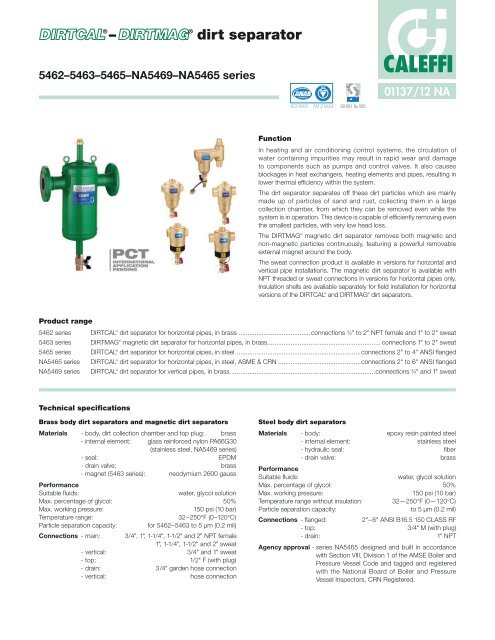
dirt separator<br />
5462–5463–5465–NA5469–NA5465 series<br />
Function<br />
ACCREDITED<br />
ISO 9001 FM 21654<br />
ISO 9001 No. 0003<br />
CALEFFI<br />
01137/12 NA<br />
In heating and air conditioning control systems, the circulation of<br />
water containing impurities may result in rapid wear and damage<br />
to components such as pumps and control valves. It also causes<br />
blockages in heat exchangers, heating elements and pipes, resulting in<br />
lower thermal efficiency within the system.<br />
The dirt separator separates off these dirt particles which are mainly<br />
made up of particles of sand and rust, collecting them in a large<br />
collection chamber, from which they can be removed even while the<br />
system is in operation. This device is capable of efficiently removing even<br />
the smallest particles, with very low head loss.<br />
The DIRTMAG ®<br />
magnetic dirt separator removes both magnetic and<br />
non-magnetic particles continuously, featuring a powerful removable<br />
external magnet around the body.<br />
The sweat connection product is available in versions for horizontal and<br />
vertical pipe installations. The magnetic dirt separator is available with<br />
NPT threaded or sweat connections in versions for horizontal pipes only.<br />
Insulation shells are available separately for field installation for horizontal<br />
versions of the DIRTCAL ®<br />
and DIRTMAG ®<br />
dirt separators.<br />
Product range<br />
5462 series DIRTCAL ®<br />
dirt separator for horizontal pipes, in brass ........................................connections 3 ⁄4" to 2" NPT female and 1" to 2" sweat<br />
5463 series DIRTMAG ®<br />
magnetic dirt separator for horizontal pipes, in brass ............................................................... connections 1" to 2" sweat<br />
5465 series DIRTCAL ®<br />
dirt separator for horizontal pipes, in steel ......................................................................connections 2" to 4" ANSI flanged<br />
NA5465 series DIRTCAL ®<br />
dirt separator for horizontal pipes, in steel, ASME & CRN ..............................................connections 2" to 6" ANSI flanged<br />
NA5469 series DIRTCAL ®<br />
dirt separator for vertical pipes, in brass .................................................................................connections 3 ⁄4" and 1" sweat<br />
Technical specifications<br />
Brass body dirt separators and magnetic dirt separators<br />
Materials - body, dirt collection chamber and top plug: brass<br />
- internal element: glass reinforced nylon PA66G30<br />
(stainless steel, NA5469 series)<br />
- seal: EPDM<br />
- drain valve: brass<br />
- magnet (5463 series): neodymium 2600 gauss<br />
Performance<br />
Suitable fluids: water, glycol solution<br />
Max. percentage of glycol: 50%<br />
Max. working pressure: 150 psi (10 bar)<br />
Temperature range: 32–250°F (0–120°C)<br />
Particle separation capacity: for 5462–5463 to 5 μm (0.2 mil)<br />
Connections - main: 3/4", 1", 1-1/4", 1-1/2" and 2" NPT female<br />
1", 1-1/4", 1-1/2" and 2" sweat<br />
- vertical: 3/4" and 1" sweat<br />
- top: 1/2" F (with plug)<br />
- drain: 3/4" garden hose connection<br />
- vertical: hose connection<br />
Steel body dirt separators<br />
Materials - body: epoxy resin painted steel<br />
- internal element: stainless steel<br />
- hydraulic seal: fiber<br />
Performance<br />
- drain valve: brass<br />
Suitable fluids: water, glycol solution<br />
Max. percentage of glycol: 50%<br />
Max. working pressure: 150 psi (10 bar)<br />
Temperature range without insulation: 32—250°F (0—120°C)<br />
Particle separation capacity: to 5 μm (0.2 mil)<br />
Connections - flanged: 2"–6" ANSI B16.5 150 CLASS RF<br />
- top: 3/4" M (with plug)<br />
- drain: 1" NPT<br />
Agency approval - series NA5465 designed and built in accordance<br />
with Section VIII, Division 1 of the AMSE Boiler and<br />
Pressure Vessel Code and tagged and registered<br />
with the National Board of Boiler and Pressure<br />
Vessel Inspectors, CRN Registered.
NPT B<br />
Sweat<br />
A<br />
A<br />
C D E<br />
546228A<br />
NPT<br />
1" SWT<br />
B<br />
5<br />
Sweat B<br />
1 ⁄16" 1 ⁄4" 5" 2" 4.2 (1.9)<br />
546235A 1 ⁄4" SWT 53 ⁄16" 1 ⁄4" 6" 2" 4.2 (1.9)<br />
C D E<br />
NPT B<br />
Sweat<br />
A<br />
NPT<br />
A<br />
Dimensions<br />
H<br />
Code A B C D E Wt. lb (kg)<br />
546205A 3 ⁄4" NPT 4 5 ⁄16" 1 1 ⁄4" 5" 2" 4.2 (1.9)<br />
546206A 1" NPT 4 5 ⁄16" 1 1 ⁄4" 5" 2" 4.2 (1.9)<br />
546207A 1 1 ⁄4" NPT 4 7 ⁄8" 1 1 ⁄4" 6" 2" 5.3 (2.4)<br />
546208A 1 1 ⁄2" NPT 4 7 ⁄8" 1 1 ⁄4" 6" 2" 6.2 (2.8)<br />
546209A 2" NPT 5 1 ⁄8" 1 1 ⁄4" 6" 2" 6.2 (2.8)<br />
546241A 1 1 ⁄2" SWT 5 3 ⁄4" 1 1 ⁄4" 6" 2" 4.9 (2.2)<br />
546254A 2" SWT 6 1 ⁄8" 1 1 ⁄4" 6" 2" 5.5 (2.5)<br />
B<br />
B<br />
G<br />
C D E<br />
BI-DIRECTIONAL<br />
Tmax 110 C Tmax 105 C<br />
Pmax 10 bar Pmax 10 bar<br />
C<br />
F<br />
C D E<br />
A<br />
A<br />
A<br />
K<br />
Sweat<br />
D<br />
A<br />
A<br />
E<br />
B<br />
B<br />
B<br />
F<br />
C D E<br />
C D E<br />
J<br />
C D E<br />
C D E<br />
WALL<br />
H<br />
NPT<br />
A<br />
H<br />
B<br />
G<br />
BI-DIRECTIONAL<br />
C<br />
F<br />
B<br />
Tmax 110 C Tmax 105 C<br />
Pmax 10 bar Pmax 10 bar<br />
B<br />
G<br />
BI-DIRECTIONAL<br />
Tmax 110 C Tmax 105 C<br />
Pmax 10 bar Pmax 10 bar<br />
C<br />
F<br />
C D E<br />
A<br />
K<br />
D<br />
A<br />
E<br />
Sweat<br />
Code A B C D E Wt. lb (kg)<br />
546306A 1" NPT 4 5 ⁄16" 1 1 ⁄4" 5" 2" 4.2 (1.9)<br />
546328A 1" SWT 5 1 ⁄16" 1 1 ⁄4" 5" 2" 4.2 (1.9)<br />
546307A 1 1 ⁄4" NPT 4 7 ⁄8" 1 1 ⁄4" 6" 2" 5.3 (2.8)<br />
546335A 1 1 ⁄4" SWT 5 3 ⁄16" 1 1 ⁄4" 6" 2" 4.2 (1.9)<br />
546308A 1 1 ⁄2" NPT 4 7 ⁄8" 1 1 ⁄4" 6" 2" 6.2 (2.8)<br />
546341A 1 1 ⁄2" SWT 5 3 ⁄4" 1 1 ⁄4" 6" 2" 4.9 (2.2)<br />
546309A 2" NPT 5 1 ⁄8" 1 1 ⁄4" 6" 2" 6.2 (2.8)<br />
546354A 2" SWT 6 1 ⁄8" 1 1 ⁄4" 6" 2" 5.5 (2.5)<br />
Code A B C D Wt. lb (kg)<br />
NA546995 3 ⁄4" SWT 5 7 ⁄8" 9 3 ⁄16" 3 3 ⁄16" 4.3 (1.95)<br />
NA546996 1" SWT 6 1 ⁄4" 9 7 ⁄8" 3 3 ⁄16" 4.3 (1.95)<br />
Code A B C D E F G H J* K Capacity (gal) Wt. lb (kg)<br />
546550A 2" 13 3 ⁄4" 1" 14 3 ⁄4" 24 7 ⁄16" 6 5 ⁄8" 3 ⁄4" 6" 6 5 ⁄16" 12" 1.8 29 (13.0)<br />
546560A 2 1 ⁄2" 13 3 ⁄4" 1" 14 3 ⁄4" 24 7 ⁄16" 6 5 ⁄8" 3 ⁄4" 7" 6 5 ⁄16" 12" 1.8 32 (14.5)<br />
546580A 3" 18 3 ⁄8" 1" 17 1 ⁄8" 29 1 ⁄8" 8 5 ⁄8" 3 ⁄4" 7 1 ⁄2" 7 5 ⁄16" 13 3 ⁄8" 4.8 51 (23.0)<br />
546510A 4" 18 1 ⁄2" 1" 17 1 ⁄8" 29 1 ⁄8" 8 5 ⁄8" 3 ⁄4" 9" 7 5 ⁄16" 13 3 ⁄8" 4.8 54 (24.0)<br />
NA546550A 2" 13 3 ⁄4" 1" 16 5 ⁄16" 23 7 ⁄8" 6 5 ⁄8" 3 ⁄4" 6" 6 5 ⁄16" 12" 1.8 38 (17.0)<br />
NA546560A 2 1 ⁄2" 13 3 ⁄4" 1" 16 5 ⁄16" 23 7 ⁄8" 6 5 ⁄8" 3 ⁄4" 7" 6 5 ⁄16" 12" 1.8 38 (17.0)<br />
NA546580A 3" 18 3 ⁄8" 1" 20 11 ⁄16" 30 5 ⁄8" 8 5 ⁄8" 3 ⁄4" 7 1 ⁄2" 7 5 ⁄16" 13 3 ⁄8" 4.8 55 (25.0)<br />
NA546510A 4" 18 3 ⁄8" 1" 20 11 ⁄16" 30 5 ⁄8" 8 5 ⁄8" 3 ⁄4" 9" 7 5 ⁄16" 13 3 ⁄8" 4.8 55 (25.0)<br />
NA546512A 5" 25" 1" 23 3 ⁄16" 34 15 ⁄16" 12 3 ⁄4" 3 ⁄4" 10" 9 3 ⁄8" 17 3 ⁄16" 13.7 138 (63.0)<br />
NA546515A 6" 25" 1" 23 3 ⁄16" 34 15 ⁄16" 12 3 ⁄4" 3 ⁄4" 10" 9 3 ⁄8" 17 3 ⁄16" 13.7 148 (67.0)<br />
*This dimension allows for a minimum of 3" wall clearance to accommodate insulation if used.<br />
A<br />
K<br />
D<br />
E<br />
F<br />
B<br />
J<br />
F<br />
WALL<br />
J<br />
C D E<br />
WALL
Operating principle<br />
1<br />
2<br />
4<br />
2<br />
3<br />
1<br />
1<br />
The dirt separator operating principle is based on the combined<br />
action of a number of physical phenomena. The internal element (1) is<br />
composed of a set of concentric diamond pattern mesh surfaces. The<br />
2<br />
dirt in the water strikes these surfaces, separates and drops into the<br />
bottom of the body (2) where they collect. In addition, the large internal<br />
3<br />
volume of DIRTCAL<br />
4<br />
®<br />
slows down the velocity of the medium and with the<br />
help of gravity, separates the contained particles.<br />
The collected dirt can then be discharged, even with the system<br />
running, by opening the drain valve (3) with the handle (4).<br />
5463 5462 NA5469<br />
Geometric structure and large dirt<br />
collection chamber<br />
3<br />
The geometrical structure of DIRTCAL<br />
4<br />
1<br />
2<br />
3<br />
4<br />
®<br />
reduces the flow media velocity<br />
to help separate dirt particles. The dirt collection chamber has the<br />
following features:<br />
• It is located at the bottom of the device at such a distance from the<br />
connections that the collected dirt is not affected by the swirl of the<br />
flow through the mesh element.<br />
• It has enough capacity to increase the amount of dirt stored and<br />
therefore decreases the frequency of emptying it compared to filters<br />
that need to be cleaned frequently.<br />
• It is easily inspected, by unscrewing it from the dirt separator body for<br />
servicing the internal mesh element when large debris are trapped in it.<br />
3<br />
4<br />
1<br />
1<br />
2<br />
3<br />
4<br />
1<br />
2<br />
3<br />
4<br />
Construction details<br />
1<br />
2<br />
2<br />
Low head losses and performance maintained over time<br />
3<br />
The dirt separating action performed by the dirt separator is based on<br />
using the internal element (1) with concentric diamond pattern mesh<br />
surfaces instead of an 4ordinary<br />
filter. The element offers little resistance<br />
to the medium flow while ensuring dirt separation. This occurs due<br />
to the particles colliding with the concentric diamond pattern mesh<br />
surfaces and then settling to the bottom, and not by filtration; which,<br />
over time, gets progressively clogged. By contrast, the DIRTCAL ®<br />
low<br />
velocity- zone dirt separator efficiently removes the particles to as small<br />
as 5 μm (0.2 mil) with very low head loss. The dirt collection chamber<br />
(2) at the bottom of the DIRTCAL ®<br />
is at the right distance from the inlet<br />
and outlet connections that the collected dirt particles are not affected<br />
by the swirling flow through the bottom drain port, even with the system<br />
running, by opening the drain valve (3) with the handle (4).<br />
4<br />
2<br />
3<br />
1<br />
3<br />
4<br />
5465/NA5465<br />
1<br />
2
Vertical DIRTCAL ®<br />
The vertical DIRTCAL<br />
1<br />
®<br />
dirt separator efficiently<br />
removes dirt particles<br />
with significantly less<br />
clogging of the internal<br />
mesh element compared<br />
to normal Y-strainers.<br />
Additionally, the large<br />
dirt collection chamber<br />
requires less frequent<br />
cleaning, which can<br />
be done by simply<br />
opening the drain<br />
valve to discharge<br />
the accumulated dirt<br />
particles, even with the<br />
system running. The<br />
special internal shape<br />
of the separator body is<br />
designed to maximize<br />
fluid flow rate with low<br />
head loss. Flow direction<br />
of the DIRTCAL ®<br />
dirt separator is bi-directional; flow in either direction<br />
is permitted.<br />
Draining off dirt<br />
The dirt separator collection chamber has a drain valve. Using the<br />
handle provided it is possible to drain off the accumulated dirt particles<br />
even with the system in operation.<br />
Maintenance<br />
To perform<br />
maintenance,<br />
simply use a 26 mm<br />
hexagon wrench (1)<br />
to unscrew the dirt<br />
collection chamber,<br />
to which the inner<br />
mesh element is<br />
connected for removal<br />
and for cleaning.<br />
1<br />
BI-DIRECTIONAL<br />
Tmax 110ϒC Tmax 105ϒC<br />
Pmax 10 bar Pmax 10 bar<br />
1<br />
DIRTMAG ®<br />
The versatile DIRTMAG ®<br />
magnetic dirt separator<br />
removes both magnetic<br />
and non-magnetic<br />
particles continuously. In<br />
addition to removing sand<br />
and rust impurities with<br />
a glass-reinforced nylon<br />
internal element in a lowvelocity-zone<br />
chamber,<br />
the DIRTMAG ®<br />
features<br />
a powerful removable<br />
external magnet around<br />
the body below the flow<br />
line for fast and effective<br />
capture of ferrous<br />
particles. The DIRTMAG ®<br />
has the magnet positioned<br />
externally to maintain low<br />
pressure loss.<br />
Use of top connector<br />
1<br />
1<br />
1<br />
The connector on top of the dirt separator can be used for optional<br />
installation of an automatic air vent valve, <strong>Caleffi</strong> code 502243A for the<br />
threaded or sweat versions, 5462 Series (A), replacing the standard<br />
1/2" NPT Male plug (code NA10044). Use <strong>Caleffi</strong> code 501502A for the<br />
flanged version 5465 and NA5465 Series (C) — replacing the standard<br />
3/4" NPT End Cap (code 41525).<br />
A C<br />
B<br />
BI-DIRECTIONAL<br />
Tmax 110ϒC Tmax 105ϒC<br />
Pmax 10 bar Pmax 10 bar<br />
Use of bottom connector<br />
1<br />
The dirt separators come complete with drain valves installed on<br />
the bottom port: <strong>Caleffi</strong> code 538402 FD for horizontal threaded or<br />
sweat versions, 5462 series (B); code 538400 for vertical versions,<br />
NA5469 series and code NA39753 for flanges version, 5465 and<br />
NA5465 series (C).
Insulation shells<br />
The brass DIRTCAL ®<br />
series 5462 for<br />
horizontal pipes and the DIRTMAG ®<br />
series 5463 can be supplied with<br />
optional insulated covers, code<br />
CBN5462xx series purchased<br />
separately, to minimize heat loss.<br />
Code Size<br />
CBN546205<br />
For 3 ⁄4" & 1"<br />
DIRTCAL ®<br />
, DIRTMAG ®<br />
CBN546207<br />
CBN546209<br />
∆p (ft of hd)<br />
1<br />
0.9<br />
0.8<br />
0.7<br />
0.6<br />
0.5<br />
0.45<br />
0.4<br />
0.35<br />
0.3<br />
0.25<br />
0.2<br />
0.18<br />
0.16<br />
0.14<br />
0.12<br />
0.1<br />
0.09<br />
0.08<br />
0.07<br />
0.06<br />
0.05<br />
0.045<br />
0.04<br />
0.035<br />
0.03<br />
0.025<br />
0.02<br />
For 1" & 1 1 ⁄2"<br />
DIRTCAL ®<br />
, DIRTMAG ®<br />
DIRTCAL ®<br />
3/4"<br />
3/4" - 1”<br />
Vertical<br />
BRASS BODY STEEL BODY<br />
1"<br />
For 2"<br />
, DIRTMAG ®<br />
Technical specifications<br />
Material: closed cell expanded PE-X<br />
Thickness: 25/64" (10 mm)<br />
Density - inner part: 1.9 lb/ft3 (30 kg/m3 )<br />
- outer part: 3.1 lb/ft3 (50 kg/m3 Thermal conductivity (DIN 52612):<br />
)<br />
- at 32ºF (0ºC): 0.263 BTU·in/hr·ft 2 ·ºF (0.038 W/(m·K)<br />
- at 104ºF (40ºC): 0.312 BTU·in/hr·ft 2 ·ºF (0.045 W/(m·K)<br />
Coefficient of resistance to water vapor (DIN 52615): >1,300<br />
Working temperature range: 32–212ºF (0–100ºC)<br />
Reaction to fire (DIN 4102): class B2<br />
Removing insulation and draining impurities (D)<br />
1. Remove the insulation by taking off the bottom casing of the collection<br />
chamber first, and if necessary, the top insulation casing later.<br />
2. Remove the magnetic ring containing the two magnets, that during<br />
operation attracted the ferrous particles.<br />
3. Flush out the ferrous and nonferrous debris by turning the handle to<br />
open the drain valve.<br />
4. When finished, replace the insulation shells.<br />
Hydraulic characteristics<br />
1-1/4"<br />
1-1/2"<br />
2”<br />
2<br />
2.5<br />
3<br />
3.5<br />
4<br />
4.5<br />
5<br />
6<br />
7<br />
8<br />
9<br />
10<br />
12<br />
14<br />
16<br />
18<br />
20<br />
25<br />
30<br />
35<br />
40<br />
45<br />
50<br />
2”<br />
2-1/2”<br />
3”<br />
4”<br />
5”<br />
6”<br />
60<br />
70<br />
80<br />
90<br />
100<br />
120<br />
140<br />
160<br />
180<br />
200<br />
250<br />
300<br />
350<br />
400<br />
450<br />
500<br />
0.20<br />
0.25<br />
0.30<br />
0.35<br />
0.40<br />
0.45<br />
0.5<br />
0.6<br />
0.7<br />
0.8<br />
0.9<br />
1<br />
1.2<br />
1.4<br />
1.6<br />
1.8<br />
2<br />
2.5<br />
3<br />
3.5<br />
4<br />
4.5<br />
5<br />
6<br />
7<br />
8<br />
9<br />
10<br />
12<br />
14<br />
16<br />
18<br />
20<br />
25<br />
30<br />
35<br />
600<br />
700<br />
800<br />
900<br />
1000<br />
40<br />
45<br />
50<br />
60<br />
70<br />
(ft of hd) (kPa)<br />
1<br />
0.9<br />
3<br />
0.8 2.5<br />
0.7<br />
0.6<br />
0.5<br />
0.45<br />
2.0<br />
1.8<br />
1.6<br />
1.4<br />
0.4 1.2<br />
0.35<br />
0.3<br />
1<br />
0.9<br />
0.25<br />
0.8<br />
0.7<br />
0.2<br />
0.18<br />
0.16<br />
0.14<br />
0.6<br />
0.5<br />
0.45<br />
0.4<br />
0.12<br />
0.35<br />
0.1<br />
0.09<br />
0.3<br />
0.08 0.25<br />
0.07<br />
0.06 0.20<br />
0.18<br />
0.05<br />
0.045<br />
0.16<br />
0.14<br />
0.04 0.12<br />
0.035<br />
0.03<br />
0.10<br />
0.09<br />
0.025<br />
0.08<br />
0.07<br />
0.02 0.06<br />
G (l/s) (gpm)<br />
D<br />
Brass body Steel body<br />
Size 3 ⁄4" 3 ⁄4"–1"* 1" 1 1 ⁄4" 1 1 ⁄2" 2" 2" 1 2 ⁄2" 3" 4" 5" 6"<br />
CV 18.8 19.9 32.6 56.6 73.3 81 88 176 211 328 520 842<br />
*Vertical versions<br />
The maximum fluid velocity recommended at the unit connections<br />
is ~ 4 f/s. The following table shows the maximum flow rates to<br />
comply with this condition.<br />
Brass body Steel body<br />
Size 3 ⁄4" 3 ⁄4"–1"* 1" 11 ⁄4" 11 ⁄2" 2" 2" 21 ⁄2" 3" 4" 5" 6"<br />
GPM 6 9.0 9.3 15.3 23.9 36 37.3 63 95.5 149 259 380<br />
l/s 0.4 0.57 0.6 1.0 1.5 2.28 2.35 3.9 6.0 9.4 16.3 24.0<br />
*Vertical versions
Tmax 105°C<br />
Pmax 10 bar<br />
BI-DIRECTIONAL<br />
Tmax 110°C<br />
Pmax 10 bar<br />
Tmax 105°C<br />
Pmax 10 bar<br />
BI-DIRECTIONAL<br />
Tmax 105°C<br />
Pmax 10 bar<br />
Tmax 110°C<br />
Pmax 10 bar<br />
BI-DIRECTIONAL<br />
Tmax 110°C<br />
Pmax 10 bar<br />
Particle separation capacity — dirt separator efficiency Separation efficiency<br />
Efficiency (%)<br />
Separated quantity.100%<br />
( Initial quantity )<br />
100<br />
80<br />
60<br />
40<br />
20<br />
0<br />
Micro<br />
particle<br />
(∆m)<br />
0<br />
BI-DIRECTIONAL<br />
Tmax 110°C Tmax 105°C<br />
Pmax 10 bar Pmax 10 bar<br />
BI-DIRECTIONAL<br />
Tmax 110°C Tmax 105°C<br />
Pmax 10 bar Pmax 10 bar<br />
BI-DIRECTIONAL<br />
Tmax 110°C Tmax 105°C<br />
Pmax 10 bar Pmax 10 bar<br />
5<br />
10<br />
BI-DIRECTIONAL<br />
Tmax 110°C Tmax 105°C<br />
Pmax 10 bar Pmax 10 bar<br />
clogging increases.<br />
BI-DIRECTIONAL<br />
Tmax 110°C Tmax 105°C<br />
Pmax 10 bar Pmax 10 bar<br />
16<br />
Tmax 105°C<br />
Pmax 10 bar<br />
BI-DIRECTIONAL<br />
Tmax 110°C<br />
Pmax 10 bar<br />
20<br />
Tmax 105°C<br />
Pmax 10 bar<br />
BI-DIRECTIONAL<br />
Tmax 105°C<br />
Pmax 10 bar<br />
Tmax 110°C<br />
Pmax 10 bar<br />
BI-DIRECTIONAL<br />
Tmax 110°C<br />
Pmax 10 bar<br />
35<br />
Efficiency<br />
50 passages (1.6 f/s)<br />
50<br />
63<br />
105<br />
WORKING ZONE<br />
DIRTCAL<br />
BI-DIRECTIONAL<br />
Tmax 110°C Tmax 105°C<br />
Pmax 10 bar Pmax 10 bar<br />
BI-DIRECTIONAL<br />
Tmax 110°C Tmax 105°C<br />
Pmax 10 bar Pmax 10 bar<br />
BI-DIRECTIONAL<br />
Tmax 110°C Tmax 105°C<br />
Pmax 10 bar Pmax 10 bar<br />
BI-DIRECTIONAL<br />
Tmax 110°C Tmax 105°C<br />
Pmax 10 bar Pmax 10 bar<br />
BI-DIRECTIONAL<br />
Tmax 110°C Tmax 105°C<br />
Pmax 10 bar Pmax 10 bar<br />
150<br />
210<br />
250<br />
Efficiency<br />
50 passages (3.2 f/s)<br />
CARTRIDGE FILTER<br />
500<br />
SPECIAL FILTER<br />
Y-STRAINERS<br />
Reduced head losses<br />
A normal Y strainer performs its function via a metal mesh selected<br />
for the size of the largest particle. The medium therefore has a<br />
consequent initial loss of head that increases as the degree of<br />
Installation<br />
The dirt separator must always be installed in a vertical position,<br />
preferably on the return circuit upstream of the boiler (or chiller).<br />
This enables it to intercept dirt particles already present in the circuit,<br />
particularly when it is first started, before they reach the boiler (or chiller).<br />
Flow direction for the DIRTCAL ®<br />
and DIRTMAG ®<br />
dirt separators is<br />
bidirectional, flowing in either direction is permitted.<br />
BI-DIRECTIONAL<br />
Tmax 110°C Tmax 105°C<br />
Pmax 10 bar Pmax 10 bar<br />
BI-DIRECTIONAL<br />
Tmax 110°C Tmax 105°C<br />
Pmax 10 bar Pmax 10 bar<br />
1000<br />
The capacity for separating the dirt in the medium circulating in the<br />
closed circuits of the hydronic systems depends on three factors:<br />
1. It increases as the size and mass of the dirt particle increases.<br />
The larger and heavier dirt particles drop before the lighter ones.<br />
2. It increases as the fluid velocity decreases. If the velocity decreases,<br />
there is a low-velocity-zone inside the dirt separator and the dirt<br />
particles separate more easily.<br />
3. It increases as the number of recirculations increases. The medium<br />
in the circuit, flowing through the dirt separator a number of times<br />
during operation, is subjected to a continuous separation, until the<br />
dirt particles are completely removed.<br />
The special design of the internal mesh element in the <strong>Caleffi</strong> DIRTCAL ®<br />
dirt separator, is able to completely separate the dirt particles in<br />
the circuit down to a minimum particle size of 5 μm (0.2 mil). The<br />
adjacent graph illustrates how DIRTCAL ®<br />
quickly separates nearly all<br />
the dirt particles. After only 50 recirculations, approximately one day<br />
of operation, up to 100% is effectively removed from the circuit for<br />
particles of diameter greater than 100 μm (3.9 mil) and on average up<br />
to 80% taking account of the smallest particles. The continual passing<br />
of the medium during normal operation of the system gradually leads to<br />
complete dirt removal.<br />
The DIRTCAL ®<br />
dirt separator, however, removes the particles striking<br />
the internal mesh element and subsequently drop into the collection<br />
chamber. The consequent head losses are greatly reduced and are not<br />
affected by the amount of dirt collected.<br />
BI-DIRECTIONAL<br />
Tmax 110°C Tmax 105°C<br />
Pmax 10 bar Pmax 10 bar<br />
BI-DIRECTIONAL<br />
Tmax 110°C Tmax 105°C<br />
Pmax 10 bar Pmax 10 bar<br />
CHILLER<br />
BI-DIRECTIONAL<br />
Tmax 110°C Tmax 105°C<br />
Pmax 10 bar Pmax 10 bar<br />
BI-DIRECTIONAL<br />
Tmax 110°C Tmax 105°C<br />
Pmax 10 bar Pmax 10 bar
Application diagram<br />
A<br />
A<br />
P<br />
P<br />
T<br />
F<br />
T<br />
F<br />
BI-DIRECTIONAL<br />
Tmax 110ϒC Tmax 105ϒC<br />
Pmax 10 bar Pmax 10 bar<br />
BI-DIRECTIONAL<br />
Tmax 110ϒC Tmax 105ϒC<br />
Pmax 10 bar Pmax 10 bar<br />
T<br />
T<br />
T<br />
T<br />
Shut-off valve<br />
Ball valve<br />
P<br />
BALLSTOP<br />
Thermometer<br />
Differential<br />
by-pass valve<br />
F Flow switch<br />
Zone valve<br />
A<br />
Pump<br />
FlowCal<br />
T<br />
<br />
Shut-off valve<br />
Ball valve<br />
3-way cock<br />
P<br />
BALLSTOP<br />
Pressure<br />
switch<br />
Thermometer<br />
Differential<br />
Control pocket<br />
by-pass valve<br />
Gas filter<br />
F Flow switch<br />
Gas regulator<br />
Zone valve<br />
Y-strainer<br />
A<br />
Pump<br />
Fuel<br />
T<br />
shut-off valve<br />
FlowCal<br />
Air separator<br />
Stub pipe<br />
Vibration<br />
damping<br />
Temperature coupler<br />
sensor<br />
Pocket<br />
Safety<br />
thermostat<br />
Pressure<br />
relief valve<br />
Regulator<br />
Expansion<br />
Backflow<br />
tank<br />
preventer<br />
<br />
3-way cock<br />
Pressure<br />
switch<br />
Control pocket<br />
Gas filter<br />
Gas regulator<br />
Y-strainer<br />
Fuel<br />
shut-off valve<br />
Air separator<br />
Stub pipe<br />
Vibration<br />
damping<br />
Temperature coupler<br />
sensor<br />
Pocket<br />
Safety<br />
thermostat<br />
Pressure<br />
relief valve<br />
Regulator<br />
Expansion<br />
Backflow<br />
tank<br />
preventer<br />
5462 Series DIRTCAL ®<br />
— Brass with Sweat and NPT connections<br />
<strong>Dirt</strong> separator in brass. NPT threaded connections from 3/4" to 2" and sweat connections 1" to 2". Top connection 1/2" F (with plug). Drain valve<br />
with 3/4" garden hose connection. Internal mesh element of glass reinforced nylon PA66G30, removable for cleaning. Brass body. EPDM hydraulic<br />
seals. Glycol maximum 50%. Maximum working pressure 150 psi (10 bar), Temperature range 32 to 250°F (0 to 120°C). Particle separating capacity<br />
5 μm (0.2 mil). Particle separating capacity 5 μm (0.2 mil). Pre-formed insulation shells available separately for field installation.<br />
5463 Series DIRTMAG ®<br />
— Brass with Sweat and NPT connections<br />
<strong>Dirt</strong> separator with magnet in brass. NPT threaded and sweat connections 1" to 2". Top connection 1/2" F (with plug). Drain valve with 3/4" garden hose<br />
connection. Internal mesh element of glass reinforced nylon PA66G30, removable for cleaning. Brass body with an external removable magnet belt,<br />
neodymium 2600 Gauss. EPDM hydraulic seals. Glycol maximum 50%. Maximum working pressure 150 psi (10 bar), Temperature range 32 to 250°F<br />
(0 to 120°C). Particle separating capacity 5 μm (0.2 mil). Pre-formed insulation shells available separately for field installation.<br />
5465 Series DIRTCAL ®<br />
— Flanged Steel<br />
<strong>Dirt</strong> separator in steel. Flanged 150 CLASS ANSI connections from 2" to 4". Top connection 3/4" F (with plug). Bottom male 1" NPT for drain. Internal<br />
mesh element of stainless steel. Fiber hydraulic seals. Glycol maximum 50%. Maximum working pressure 150 psi (10 bar). Temperature range 32 to<br />
250°F (0 to 120°C). Particle separating capacity 5 μm (0.2 mil).<br />
NA5465 Series DIRTCAL ®<br />
— Flanged Steel*<br />
<strong>Dirt</strong> separator in steel. Flanged 150 CLASS ANSI connections from 2" to 6". Top connection 3/4" F (with plug). Bottom male 1" NPT for drain. Internal<br />
mesh element of stainless steel. Fiber hydraulic seals. Glycol maximum 50%. Maximum working pressure 150 psi (10 bar). Temperature range 32 to<br />
250°F (0 to 120°C). Particle separating capacity 5 μm (0.2 mil).<br />
*Flanged series NA5465 are designed and built in accordance with Section VIII, Division 1 of the AMSE Boiler and Pressure Vessel Code and tagged<br />
and registered with the National Board of Boiler and Pressure Vessel Inspectors, CRN Registered.<br />
We reserve the right to change our products and their relevant technical data, contained in this publication, at any time and without prior notice.<br />
<strong>Caleffi</strong> North America, Inc.<br />
3883 W. Milwaukee Road<br />
Milwaukee, WI 53208<br />
Tel: 414-238-2360 · Fax: 414-238-2366<br />
sales@caleffi.com · www.caleffi.us<br />
© Copyright 2012 <strong>Caleffi</strong> North America, Inc.<br />
SPECIFICATION SUMMARIES<br />
NA5469 Series DIRTCAL ®<br />
— Brass with Sweat connections<br />
<strong>Dirt</strong> separator in brass. For vertical pipe installations sweat connections 3/4" to 1". Drain valve with hose connection. Internal mesh element of stainless<br />
steel, removable for cleaning. Brass body. EPDM hydraulic seals. Glycol maximum 50%. Maximum working pressure 150 psi (10 bar). Temperature range<br />
32 to 250°F (0 to 120°C).<br />
T<br />
T


