

Composite manifolds specifically designed for radiant panel ... - Caleffi
Composite manifolds specifically designed for radiant panel ... - Caleffi
Composite manifolds specifically designed for radiant panel ... - Caleffi

You also want an ePaper? Increase the reach of your titles
YUMPU automatically turns print PDFs into web optimized ePapers that Google loves.
<strong>Composite</strong> <strong>manifolds</strong> <strong>specifically</strong><br />
<strong>designed</strong> <strong>for</strong> <strong>radiant</strong> <strong>panel</strong> systems<br />
670 series<br />
Product range<br />
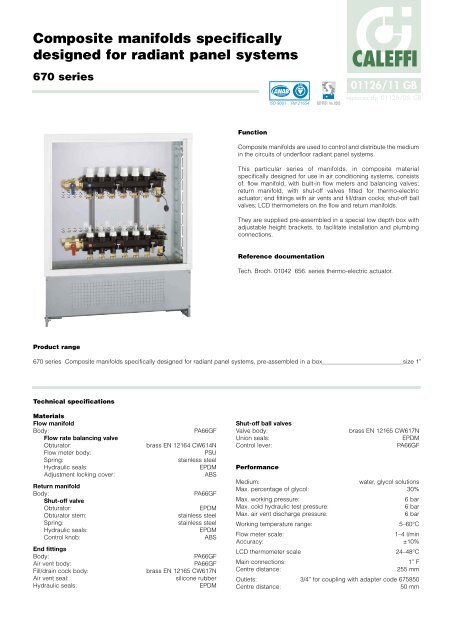
Function<br />
01126/11 GB<br />
replaces dp 01126/05 GB<br />
<strong>Composite</strong> <strong>manifolds</strong> are used to control and distribute the medium<br />
in the circuits of underfloor <strong>radiant</strong> <strong>panel</strong> systems.<br />
This particular series of <strong>manifolds</strong>, in composite material<br />
<strong>specifically</strong> <strong>designed</strong> <strong>for</strong> use in air conditioning systems, consists<br />
of: flow manifold, with built-in flow meters and balancing valves;<br />
return manifold, with shut-off valves fitted <strong>for</strong> thermo-electric<br />
actuator; end fittings with air vents and fill/drain cocks; shut-off ball<br />
valves; LCD thermometers on the flow and return <strong>manifolds</strong>.<br />
They are supplied pre-assembled in a special low depth box with<br />
adjustable height brackets, to facilitate installation and plumbing<br />
connections.<br />
Reference documentation<br />
CALEFFI<br />
Tech. Broch. 01042 656. series thermo-electric actuator.<br />
670 series <strong>Composite</strong> <strong>manifolds</strong> <strong>specifically</strong> <strong>designed</strong> <strong>for</strong> <strong>radiant</strong> <strong>panel</strong> systems, pre-assembled in a box size 1”<br />
Technical specifications<br />
Materials<br />
Flow manifold<br />
Body: PA66GF<br />
Flow rate balancing valve<br />
Obturator: brass EN 12164 CW614N<br />
Flow meter body: PSU<br />
Spring: stainless steel<br />
Hydraulic seals: EPDM<br />
Adjustment locking cover: ABS<br />
Return manifold<br />
Body: PA66GF<br />
Shut-off valve<br />
Obturator: EPDM<br />
Obturator stem: stainless steel<br />
Spring: stainless steel<br />
Hydraulic seals: EPDM<br />
Control knob: ABS<br />
End fittings<br />
Body: PA66GF<br />
Air vent body: PA66GF<br />
Fill/drain cock body: brass EN 12165 CW617N<br />
Air vent seal: silicone rubber<br />
Hydraulic seals: EPDM<br />
Shut-off ball valves<br />
Valve body: brass EN 12165 CW617N<br />
Union seals: EPDM<br />
Control lever: PA66GF<br />
Per<strong>for</strong>mance<br />
ACCREDITED<br />
ISO 9001 FM 21654<br />
ISO 9001 No. 0003<br />
Medium: water, glycol solutions<br />
Max. percentage of glycol: 30%<br />
Max. working pressure: 6 bar<br />
Max. cold hydraulic test pressure: 6 bar<br />
Max. air vent discharge pressure: 6 bar<br />
Working temperature range: 5–60°C<br />
Flow meter scale: 1–4 l/min<br />
Accuracy: ±10%<br />
LCD thermometer scale 24–48°C<br />
Main connections: 1” F<br />
Centre distance: 255 mm<br />
Outlets: 3/4” <strong>for</strong> coupling with adapter code 675850<br />
Centre distance: 50 mm
Code<br />
No. of outlets<br />
A<br />
B (box width)<br />
Mass (kg)<br />
6706C1<br />
3<br />
300<br />
600<br />
14,8<br />
6706D1<br />
4<br />
350<br />
600<br />
15,0<br />
6706E1<br />
5<br />
400<br />
600<br />
15,2<br />
6706F1<br />
6<br />
450<br />
600<br />
15,4<br />
6706G1<br />
7<br />
500<br />
800<br />
19,4<br />
6706H1<br />
8<br />
550<br />
800<br />
19,6<br />
6706I1<br />
9<br />
600<br />
800<br />
19,8<br />
6706L1<br />
10<br />
650<br />
800<br />
20,0<br />
535<br />
A<br />
50<br />
235∏325<br />
110<br />
1<br />
2<br />
3<br />
4<br />
L/MIN<br />
1<br />
2<br />
3<br />
4<br />
L/MIN<br />
1<br />
2<br />
3<br />
4<br />
L/MIN<br />
1<br />
2<br />
3<br />
4<br />
L/MIN<br />
1<br />
2<br />
3<br />
4<br />
L/MIN<br />
1<br />
2<br />
3<br />
4<br />
L/MIN<br />
B<br />
30<br />
48<br />
6706M1<br />
11<br />
700<br />
800<br />
20,2<br />
6706N1<br />
12<br />
750<br />
800<br />
20,4<br />
BAGNO<br />
ENTRATA<br />
PRANZO<br />
CUCINA<br />
CAMERA<br />
C. MATRIM.<br />
BAGNO<br />
ENTRATA<br />
PRANZO<br />
CUCINA<br />
CAMERA<br />
C. MATRIM.<br />
∞C<br />
∞C<br />
80∏120<br />
255 195<br />
43<br />
1”<br />
1”<br />
91<br />
65 70<br />
6∞<br />
Dimensions
Characteristic components<br />
12<br />
2<br />
4<br />
9<br />
11<br />
1<br />
Pre-assembled unit complete with:<br />
CAMERA<br />
1<br />
2<br />
3<br />
4<br />
L/MIN<br />
CAMERA<br />
C. MATRIM.<br />
1<br />
2<br />
3<br />
4<br />
L/MIN<br />
C. MATRIM.<br />
∞C<br />
PRANZO<br />
1<br />
2<br />
3<br />
4<br />
L/MIN<br />
∞C<br />
PRANZO<br />
ENTRATA<br />
10 5 6<br />
1) Flow manifold with built-in flow meters and flow rate balancing valves<br />
2) Return manifold with built-in shut-off valves fitted <strong>for</strong> thermo-electric actuator<br />
3) End fittings complete with automatic air vent with hygroscopic cap, drain valve and fill/drain cock<br />
4) Pair of shut-off ball valves<br />
5) LCD thermometers on the flow and return <strong>manifolds</strong><br />
6) Adhesive labels indicating the rooms<br />
7) Pair of mounting brackets <strong>for</strong> box installation<br />
8) Box with adjustable height and depth<br />
9) Coupling adapter with clip code 675850<br />
10) Template <strong>for</strong> cutting pipe code 675002<br />
Accessories<br />
11) 680 series Darcal self-adjustable diameter fitting <strong>for</strong> single and multi-layer plastic pipe<br />
12) 6561 series thermo-electric actuator<br />
13) Push-fit thermometer <strong>for</strong> <strong>panel</strong> circuit code 675900<br />
1<br />
2<br />
3<br />
4<br />
L/MIN<br />
ENTRATA<br />
CUCINA<br />
1<br />
2<br />
3<br />
4<br />
L/MIN<br />
CUCINA<br />
BAGNO<br />
∞C<br />
50 50<br />
40 40<br />
30 30<br />
20 20<br />
10 10<br />
1<br />
2<br />
3<br />
4<br />
L/MIN<br />
BAGNO<br />
8<br />
3<br />
7<br />
13
Construction details<br />
Specific composite material<br />
The <strong>manifolds</strong> are made using a polymer <strong>specifically</strong> selected <strong>for</strong> heating and cooling system applications. The basic characteristics required<br />
<strong>for</strong> this purpose are:<br />
- high strain strength while maintaining good ultimate elongation<br />
- good resistance to crack propagation<br />
- very low humidity absorption, <strong>for</strong> consistent mechanical behaviour<br />
- high resistance to abrasion due to continuous medium flow<br />
- per<strong>for</strong>mance maintained as temperature varies<br />
- compatibility with glycols and additives used in circuits<br />
These basic material characteristics, combined with the appropriate shaping of the most highly stressed areas, enable a comparison with the<br />
metals typically used in the construction of distribution <strong>manifolds</strong>.<br />
Return manifold<br />
The return manifold is equipped with built-in shut-off valves.<br />
Using the shut-off valve with manual knob, the flow rate to the<br />
individual circuits can be reduced up to completely shutting the<br />
circuit off. The valve is equipped with a stainless steel single-piece<br />
control stem, with a double O-Ring seal. The rubber obturator is<br />
specially shaped to minimise head losses and the noise produced<br />
by the flow of the medium, preventing potential seal seat sticking.<br />
The valves are fitted to accommodate a thermo-electric actuator in<br />
order to make them automatic on receiving a signal from a room<br />
thermostat.<br />
Flow manifold<br />
The flow manifold is equipped with built-in flow meters and flow rate<br />
balancing valves.<br />
Using the balancing valve with the special tapered obturator, the<br />
flow rate to the individual circuits can be adjusted accurately as<br />
required, with the setting being read directly from the single flow<br />
meter with a scale of 1–4 l/min. This simplifies and speeds up the<br />
circuit balancing process, with no need <strong>for</strong> reference graphs. After<br />
adjustment, the valve can be locked in its open position by means<br />
of its tamper-proof cover.<br />
The same valve makes it possible to seal off the individual circuit, if<br />
necessary.
Manifold compatibility<br />
The <strong>manifolds</strong> and end fittings<br />
can be coupled together,<br />
thanks to the threaded<br />
connections with O-Ring seals<br />
and fixing clips which prevent<br />
unscrewing. With this<br />
connection system, the<br />
assembly of the various<br />
components is simplified and<br />
the watertightness is fully<br />
assured.<br />
End fitting<br />
The end fitting is equipped with an air vent with hygroscopic safety<br />
cap, drain valve and fill/drain ball cock.<br />
The air vent is equipped with a mechanism to remove air using a<br />
silicone rubber obturator. The vent mechanism is connected to the<br />
valve body by a fixing clip, making any inspection and maintenance<br />
work easier.<br />
Nevertheless, the hygroscopic safety cap prevents water from<br />
getting out in order to protect the installation. The manual drain<br />
valve speeds up circuit filling, which takes place using the drain/fill<br />
ball cock.<br />
Digital thermometers<br />
An LCD thermometer is fitted on the flow and return manifold body, on<br />
both sides, with a temperature range of 24–48°C. The liquid crystals<br />
automatically light up green to indicate the measured temperature,<br />
making it easy to read even in poor lighting conditions.<br />
This thermometer is calibrated to display the actual temperature of<br />
the medium, which is essential in evaluating the operating<br />
conditions and thermal load of the system.<br />
Replaceable components<br />
The headwork of the balancing valve with flow meter and the shutoff<br />
valve can be removed and replaced with spare parts.<br />
Panel circuit outlets<br />
The outlet connections of the individual <strong>panel</strong> circuits are <strong>designed</strong><br />
<strong>for</strong> use with a special coupling adapter, with fixing clip, that can be<br />
removed. The brass adapter has a double O-Ring seal and a<br />
hexagonal control on its<br />
surface. The <strong>panel</strong> circuit pipe<br />
fitting is connected directly<br />
onto the threaded side.<br />
With this particular connection<br />
system, the fitting with the<br />
adapter can be tightened onto<br />
the pipe outside the box and<br />
then coupled onto the manifold<br />
body later, making hydraulic<br />
installation simpler and more<br />
practical.<br />
Room identification<br />
On the manifold body, at each<br />
individual <strong>panel</strong> circuit outlet, there is a<br />
special seat <strong>for</strong> affixing an adhesive<br />
label identifying the corresponding<br />
room.
Thermometers <strong>for</strong> circuit pipes<br />
A special alcohol thermometer<br />
with scale of 5–50°C is available<br />
as an accessory; it is equipped<br />
with push-fit plastic body <strong>for</strong> the<br />
individual <strong>panel</strong> pipe, with<br />
external diameter of 15 to 18 mm.<br />
When installed on the return pipe,<br />
this thermometer measures the<br />
actual temperature of the<br />
medium returning from the circuit,<br />
making it easy to accurately<br />
check the thermal exchange<br />
condition of the individual <strong>panel</strong>.<br />
Bracketing<br />
The <strong>manifolds</strong> have holes <strong>for</strong><br />
fixing to brackets, so they can<br />
be housed in boxes. The<br />
<strong>manifolds</strong> are reversible, so<br />
they can be positioned with the<br />
inlet on the right or left. The<br />
return manifold, located at the<br />
top, is installed at a specific<br />
angle to make it easier <strong>for</strong> the<br />
<strong>panel</strong> circuit pipes to pass<br />
through, with diameters up to<br />
20 mm.<br />
The <strong>manifolds</strong> can thus be<br />
bracketed in a box just 80 mm<br />
deep, which can even be<br />
installed in walls with reduced<br />
thickness.<br />
Shut-off valves<br />
The shut-off ball valve on the<br />
flow and return of the circuits is<br />
the union type with an EPDM<br />
flat-seat seal.<br />
Box<br />
The <strong>manifolds</strong> are supplied bracketed in a recessed sheet steel box<br />
with an adjustable depth of 80 to 120 mm. The box, <strong>specifically</strong><br />
<strong>designed</strong> <strong>for</strong> use with <strong>radiant</strong> <strong>panel</strong> systems, is equipped with floor<br />
brackets adjustable in height from 235 to 325 mm, the height being<br />
selected in accordance with the slab thickness. With these<br />
brackets, the pipe passageway is clear of obstruction; a double<br />
curtain wall then enables the direct application of plaster and the<br />
frame and cover to be fitted correctly. The back wall of the box has<br />
grooves and holes to secure the manifold brackets; the side and top<br />
walls have holes <strong>for</strong> the main pipes to pass through.<br />
The cover is opened and closed using a special handle with a pushfit<br />
clamp, without using any spanners or tools.<br />
The box is also fitted <strong>for</strong> connection to the main pipes coming in<br />
from the top.
Hydraulic characteristics<br />
In order to determine the hydraulic characteristics of the circuit, it is necessary to calculate the total head loss suffered by the flow rate of medium<br />
on passing through the devices <strong>for</strong>ming the manifold assembly and the <strong>radiant</strong> <strong>panel</strong> circuits.<br />
From a hydraulic point of view, the system consisting of the manifold assembly and the circuits can be represented as a set of hydraulic elements<br />
arranged in series and in parallel.<br />
G Tot.<br />
∆P Tot.<br />
∆P VB<br />
G Tot.<br />
∆P Manif. F<br />
∆P VB<br />
∆P VB<br />
∆P BV<br />
∆P Loop<br />
∆P Tot.<br />
∆P Loop<br />
CAMERA<br />
1<br />
2<br />
3<br />
4<br />
L/MIN<br />
CAMERA<br />
C. MATRIM.<br />
1<br />
2<br />
3<br />
4<br />
L/MIN<br />
C. MATRIM.<br />
∆P SV<br />
G Loop<br />
∆P Manif. R<br />
∞C<br />
PRANZO<br />
1<br />
2<br />
3<br />
4<br />
L/MIN<br />
∞C<br />
PRANZO<br />
ENTRATA<br />
1<br />
2<br />
3<br />
4<br />
L/MIN<br />
ENTRATA<br />
∆P Manif. F<br />
∆P Manif. R<br />
∆PTot. = Total loss at the ends of the manifold<br />
(Flow + Return + Loop)<br />
∆PBV = Localised loss at loop balancing valve<br />
(loop flow rate)<br />
∆PLoop = Loop loss (loop flow rate)<br />
∆PSV = Localised loss <strong>for</strong> <strong>panel</strong> circuit shut-off<br />
valve<br />
(loop flow rate)<br />
∆PManif. F= Distributed loss of the flow manifold (total<br />
flow rate)<br />
∆PManif. R= Distributed loss of the return manifold<br />
(total flow rate)<br />
∆PVB = Ball valve loss<br />
(total flow rate)<br />
∆PTot. = ∆PBV +∆PLoop + ∆PSV + ∆PManif. F + ∆PManif. R + ∆PVB x 2<br />
When the hydraulic characteristics of each component and the design flow rates are known, the total loss can be calculated as the sum of the<br />
partial head losses <strong>for</strong> each specific component in the system, as indicated by the <strong>for</strong>mula (1.1).<br />
∆P SV<br />
CUCINA<br />
1<br />
2<br />
3<br />
4<br />
L/MIN<br />
CUCINA<br />
BAGNO<br />
∆P BV<br />
1<br />
2<br />
3<br />
4<br />
L/MIN<br />
BAGNO<br />
∆P VB<br />
G Tot.<br />
G Loop<br />
(1.1)
Hydraulic characteristics<br />
∆p (mm w.g.)<br />
1000<br />
500<br />
200<br />
100<br />
50<br />
Example of total head loss calculation<br />
Supposing we need to calculate the head loss of a manifold with three circuits with the following characteristics:<br />
Total manifold flow rate: 350 l/h<br />
The flow rate and head loss of the three loops are as follows:<br />
Circuit 1 Circuit 2 Circuit 3<br />
∆P1= 10 kPa ∆P2= 15 kPa ∆P3= 7 kPa (1.2)<br />
G1= 120 l/h G2= 150 l/h G2= 80 l/h<br />
Each segment of the <strong>for</strong>mula (1.1) is calculated using the following relationship:<br />
∆P=G 2 /Kv 0,01 2<br />
· G= flow rate in l/h<br />
· ∆P = head loss in kPa (1 kPa = 100 mm w.g.)<br />
· Kv 0,01 = flow rate in l/h through the device, which corresponds to a head loss of 1 kPa<br />
It should be highlighted that the calculation of ∆PTot. must be made taking account of the circuit in which there are the greatest head losses<br />
distributed along the entire <strong>panel</strong> pipe loop.<br />
In the case we are examining, the relevant circuit is No. 2.<br />
It follows that:<br />
∆PBV = 1502 /1002 = 2,25 kPa<br />
∆PLoop = 15 kPa<br />
= 1502 /2402 = 0,39 kPa<br />
∆PSV<br />
∆PManif. F= 350 2 /1600 2 = 0,05 kPa } Values obtained by disregarding changes due to drawing off flow rate to the individual branched circuits<br />
∆PManif. R= 350 2 /1600 2 = 0,05 kPa<br />
∆PVB<br />
900<br />
800<br />
700<br />
600<br />
450<br />
400<br />
350<br />
300<br />
250<br />
180<br />
160<br />
140<br />
120<br />
90<br />
80<br />
70<br />
60<br />
45<br />
40<br />
35<br />
30<br />
20<br />
10<br />
25<br />
18<br />
16<br />
14<br />
12<br />
20<br />
25<br />
30<br />
35<br />
40<br />
45<br />
50<br />
60<br />
70<br />
80<br />
90<br />
= 350 2 /1650 2 = 0,04 kPa<br />
Using <strong>for</strong>mula (1.1), adding up all the calculated terms, we obtain:<br />
∆PTot.= 2,25 + 15 + 0,39 + 0,05 + 0,05 + 0,04 ≈ 17,64 kPa<br />
100<br />
120<br />
140<br />
160<br />
180<br />
Flow rate balancing valve fully open (671 series)<br />
Lockshield valve fully open (673 series)<br />
Shut-off valve<br />
- Kv = flow rate in m 3 /h <strong>for</strong> a head loss of 1 bar<br />
- Kv 0,01 = flow rate in l/h <strong>for</strong> a head loss of 1 kPa<br />
200<br />
250<br />
300<br />
350<br />
Kv<br />
1,00<br />
2,68<br />
2,40<br />
400<br />
450<br />
500<br />
∆p (kPa)<br />
9<br />
8<br />
7<br />
6<br />
Note:<br />
We can ignore the three terms <strong>for</strong> the head losses associated with the ball valves and <strong>manifolds</strong> because of their low values.<br />
In general, the total head loss is fairly close to the branched <strong>panel</strong> circuit head loss.<br />
2,5<br />
10<br />
5<br />
4,5<br />
4<br />
3,5<br />
3<br />
2<br />
1,8<br />
1,6<br />
1,4<br />
1,2<br />
1<br />
0,9<br />
0,8<br />
0,7<br />
0,6<br />
0,25<br />
0,5<br />
0,45<br />
0,4<br />
0,35<br />
0,3<br />
0,2<br />
0,18<br />
0,16<br />
0,14<br />
0,12<br />
0,1<br />
G (l/h)<br />
Kv 0,01<br />
100<br />
268<br />
240<br />
∆p (mm w.g.)<br />
1000<br />
500<br />
200<br />
100<br />
900<br />
800<br />
700<br />
600<br />
450<br />
400<br />
350<br />
300<br />
180<br />
160<br />
140<br />
120<br />
90<br />
80<br />
70<br />
60<br />
50<br />
250<br />
45<br />
40<br />
35<br />
30<br />
20<br />
10<br />
25<br />
18<br />
16<br />
14<br />
12<br />
500<br />
600<br />
700<br />
800<br />
1000<br />
Flow or return manifold 3 - 6 outlets<br />
Flow or return manifold 7 - 12 outlets<br />
Flow or return manifold 11 - 12 outlets<br />
Ball valve<br />
* Average value<br />
900<br />
1200<br />
1400<br />
1600<br />
1800<br />
2000<br />
2500<br />
3000<br />
Kv<br />
16,0*<br />
12,0*<br />
10,0*<br />
16,5*<br />
3500<br />
G (l/h)<br />
∆p (kPa)<br />
4000<br />
9<br />
8<br />
7<br />
6<br />
2,5<br />
Kv 0,01<br />
1600*<br />
1200*<br />
1000*<br />
1650*<br />
10<br />
5<br />
4,5<br />
4<br />
3,5<br />
3<br />
2<br />
1,8<br />
1,6<br />
1,4<br />
1,2<br />
1<br />
0,9<br />
0,8<br />
0,7<br />
0,6<br />
0,25<br />
0,5<br />
0,45<br />
0,4<br />
0,35<br />
0,3<br />
0,2<br />
0,18<br />
0,16<br />
0,14<br />
0,12<br />
0,1
Using the balancing valves with flow meter<br />
The balancing valves in the flow manifold make it possible to balance each individual <strong>panel</strong> circuit to obtain the design flow rates in each loop.<br />
Considering the following data:<br />
- medium flow rate across each circuit<br />
- head loss generated in each circuit by this flow rate:<br />
∆PCircuit = ∆PLoop + ∆PSV (∆PShut-off valve)<br />
- available head on the <strong>panel</strong> circuit or predefined head:<br />
HPredefined ≥∆PCircuit + = ∆PBV + ∆PLoop + ∆PSV<br />
disadvantaged<br />
Referring to the adjacent diagram, <strong>for</strong> the loop flow rate the balancing valve must<br />
provide an additional head loss equal to the difference ∆PBV (∆PBalancing valve).<br />
Flow rate balancing and direct reading<br />
HPredefined ≥ ∆PCircuit<br />
+ disadvantaged<br />
Lift the locking cover with the aid of a screwdriver and turn it over onto the flow meter. Adjust the flow rate of the individual <strong>panel</strong>s by turning<br />
the flow meter body acting on the built-in balancing valve.<br />
The flow rate must be read on the graduated scale, expressed in l/min, printed on the flow meter itself.<br />
After making all the adjustments, reposition and lock all the knobs in their seats to prevent tampering.<br />
∆P Tot.<br />
SPECIFICATION SUMMARY<br />
SV<br />
BV<br />
∆PCircuit<br />
670 series<br />
<strong>Composite</strong> distribution manifold <strong>specifically</strong> <strong>designed</strong> <strong>for</strong> <strong>radiant</strong> <strong>panel</strong> systems with 3 (from 3 to 12) outlets. PA66GF<br />
body. EPDM seals. Threaded main connections 1” F. Outlet connections 3/4” M. Medium water and glycol solutions.<br />
Maximum percentage of glycol 30%. Maximum working pressure 4 bar. Working temperature range 5–60°C. Maximum<br />
automatic air vent discharge pressure 6 bar.<br />
Complete with:<br />
- Flow manifold complete with flow rate balancing valves and flow meter with graduated scale 1–4 l/min.<br />
Accuracy ± 10%.<br />
- Return manifold complete with shut-off valves fitted <strong>for</strong> thermo-electric actuator.<br />
- Pair of end fittings complete with automatic air vent with hygroscopic cap, drain valve and fill/drain cock.<br />
- Pair of shut-off ball valves, brass body. EPDM union seals.<br />
- LCD thermometers on the flow and return <strong>manifolds</strong>. Scale 24–48°C.<br />
- Adhesive labels indicating the rooms.<br />
- Pair of fixing brackets.<br />
- Painted sheet metal box with closure clamp; adjustable depth from 80 to 120 mm; with floor brackets adjustable from<br />
235 to 325 mm.<br />
- Coupling adapters with fixing clip code 675850 <strong>for</strong> manifold outlet and 680 series fitting connection.<br />
- Pipe cutting template code 675002.<br />
∆P BV
Accessories<br />
675<br />
Coupling adapter with fixing clip code 675850 <strong>for</strong> 670 series manifold<br />
outlet and 680 series fitting connection.<br />
Size: 3/4” M - Ø 18 <strong>for</strong> clip coupling.<br />
Technical specifications<br />
Materials<br />
Body brass EN 12164 CW614N<br />
Seal: two EPDM O-Rings<br />
Fixing clip: stainless steel<br />
Per<strong>for</strong>mance<br />
Medium water, glycol solutions<br />
Max. percentage of glycol: 30%<br />
Max. working pressure: 10 bar<br />
Working temperature range: 0–100°C<br />
5–60°C (coupled in the manifold 670)<br />
Connection: 3/4” M - Ø 18 <strong>for</strong> clip coupling<br />
Technical specifications<br />
680<br />
Self-adjusting diameter fitting <strong>for</strong> single and multi-layer plastic pipes.<br />
Patented.<br />
Size: 3/4”.<br />
Materials<br />
Body and nut: brass EN 12164 CW614N<br />
Pipe clenching ring: PA66GF<br />
Seals and dielectric seal: EPDM<br />
Per<strong>for</strong>mance<br />
Medium: water, glycol solutions<br />
Max. percentage of glycol: 30%<br />
Max. working pressure: 10 bar<br />
Working temperature range: 5–80°C (PE-X)<br />
5–75°C (Multi-layer marked 95°C)<br />
Connection: 3/4”<br />
Construction details<br />
Pipe-fitting coupling flexibility<br />
This fitting is <strong>specifically</strong> <strong>designed</strong> in order to adjust to several pipe diameters. The great variety of<br />
single and multi-layer plastic pipes on the market, and the range of permissible tolerances, have<br />
made it necessary to design a specific fitting.<br />
Keeping the nominal dimensions of the fittings currently on the market, the new construction<br />
solution makes it possible to use the same fitting <strong>for</strong> pipes with external diameter differences of<br />
up to 2 mm and internal diameter differences of up to 0,5 mm.<br />
Pull-out resistance<br />
This fitting offers high resistance to pipe pull-out. Its special tightening system makes it suitable <strong>for</strong><br />
all applications, ensuring a perfect hydraulic seal.<br />
Low head losses<br />
The internal profile of the adapter (1) is shaped to obtain a Venturi effect as the medium flows.<br />
It allows <strong>for</strong> a head loss 20% lower than that corresponding to passages of the same diameter.<br />
Dielectric seal ring<br />
The fitting is equipped with a rubber insulating element (2) to prevent contact between the<br />
aluminium in the multi-layer pipe and the brass of the fitting. This prevents any galvanic<br />
corrosion generated by the two different metals.<br />
Double O-Ring seal<br />
On the adapter there are two EPDM O-Ring seals (3) - (4) in order to avoid potential losses even<br />
at high working pressures.<br />
1<br />
2<br />
3<br />
4<br />
Code Ø inner<br />
680507<br />
680502<br />
680503<br />
680500<br />
680501<br />
680506<br />
680515<br />
680517<br />
680524<br />
680526<br />
680535<br />
680537<br />
680544<br />
680546<br />
680555<br />
680556<br />
680564<br />
680505<br />
3/4”<br />
3/4”<br />
3/4”<br />
3/4”<br />
3/4”<br />
3/4”<br />
3/4”<br />
3/4”<br />
3/4”<br />
3/4”<br />
3/4”<br />
3/4”<br />
3/4”<br />
3/4”<br />
3/4”<br />
3/4”<br />
3/4”<br />
3/4”<br />
Pipe (mm)<br />
Øouter 7,5 –18,0 10,5 – 12<br />
7,5 –18,0 12,0– 14<br />
8,5 –19, 12,0– 14<br />
9,0 –19,5 14,0– 16<br />
9,5 – 10 12,0– 14<br />
9,5 – 10 14,0– 16<br />
10,5 – 11, 14,0– 16<br />
10,5 – 11,0 16,0– 18<br />
11,5 – 12,0 14,0– 16<br />
11,5 – 12,0 16,0– 18<br />
12,5 – 13,0 16,0– 18<br />
12,5 – 13,0 18,0– 20<br />
13,5 – 14,0 16,0– 18<br />
13,5 – 14,0 18,0– 20<br />
14,5 – 15,0 18,0– 20<br />
15,5– 15,5 18,0– 20<br />
15,5 – 16,0 18,0– 20<br />
1716,0 22,50
Standard thermo-electric actuators<br />
6561 tech. broch. 01042<br />
Thermo-electric actuator <strong>for</strong> <strong>manifolds</strong>.<br />
Normally closed.<br />
Code Voltage (V)<br />
656102<br />
656104<br />
6561<br />
230<br />
224<br />
tech. broch. 01042<br />
Thermo-electric actuator <strong>for</strong> <strong>manifolds</strong>.<br />
Normally closed.<br />
With auxiliary microswitch.<br />
Code<br />
656112<br />
656114<br />
Voltage (V)<br />
230<br />
224<br />
675<br />
Push-fit thermometer <strong>for</strong> <strong>panel</strong> pipe, code<br />
675900.<br />
Technical specifications<br />
Material<br />
Body: PA6GF<br />
Thermometer fluid: alcohol<br />
Per<strong>for</strong>mance<br />
Thermometer scale: 5–50°C<br />
Max. working temperature: 60°C<br />
Range of external pipe diameter (Øe): from 15 to 18 mm<br />
Conducting paste supplied in package<br />
Technical specifications<br />
SPECIFICATION SUMMARY<br />
Materials<br />
Protective shell: self-extinguishing polycarbonate<br />
Colour: (code 656102/04) white RAL 9010<br />
(code 656112/14) grey RAL 9002<br />
Per<strong>for</strong>mance<br />
Normally closed<br />
Electric supply: 230 V (ac) - 24 V (ac) - 24 V (dc)<br />
Starting current: ≤ 1 A<br />
Running current: 230 V (ac) = 13 mA<br />
24 V (ac) - 24 V (dc) = 140 mA<br />
Power consumption: 3 W<br />
Auxiliary microswitch contact rating (code 656112/114):0,8 A (230 V)<br />
Protection class: IP 44 (in vertical position)<br />
Double insulation construction: CE<br />
Max. ambient temperature: 50°C<br />
Operating time: opening and closing from 120 s to 180 s.<br />
Length of supply cable: 80 cm.<br />
695<br />
System test pump code 695000.<br />
Complete with pressure gauge<br />
and hose <strong>for</strong> connecting to the<br />
system. Also suitable <strong>for</strong> use<br />
with glycol solutions <strong>for</strong> solar<br />
thermal systems.<br />
Technical specifications<br />
Material<br />
Body bronze<br />
Piston: brass<br />
Control lever:<br />
Per<strong>for</strong>mance<br />
galvanised steel<br />
Max. working pressure: 50 bar<br />
Water content: 12 l<br />
Pressure gauge scale: 0–60 bar<br />
Hose connection: 1/2”<br />
Length of hose: 1,5 m<br />
680 series<br />
Self-adjusting diameter fitting <strong>for</strong> single and multi-layer plastic pipes with internal profile offering a Venturi effect to limit head<br />
losses. Size 3/4” F. Brass nut and adapter, EPDM seals, EPDM dielectric ring, PA66GF olive. Medium water and glycol solutions.<br />
Maximum percentage of glycol 30%. Maximum working pressure 10 bar. Working temperature range 5–80°C (PE-X); 5–75°C<br />
(Multi-layer marked 95°C).<br />
675 series<br />
Push-fit thermometer <strong>for</strong> <strong>panel</strong> pipe. Working range of external pipe diameter: from 15 to 18 mm. PA6GF body. Thermometer<br />
fluid alcohol. Thermometer scale 5–50°C. Maximum working temperature 60°C.<br />
6561 series<br />
Thermo-electric actuator. Normally closed (Normally closed with auxiliary microswitch). Electric supply 230 V (ac); 24 V (ac);<br />
24 V (dc). Starting current ≤ 1 A. Running current 13 mA (230 V (ac)), 140 mA (24 V (ac) - 24 V (dc)). Running power<br />
consumption 3 W. Protection class IP 44 (in vertical position). Maximum ambient temperature 50°C. Operating time from 120<br />
to 180 seconds. Length of supply cable 80 cm.<br />
695 series<br />
System test pump with 0–60 bar pressure gauge and 1,5 m hose. Hose connection 1/2”. Maximum working pressure<br />
50 bar. Water content 12 l.
�� �� �� �� � ��<br />
���<br />
�� �� � ��<br />
�<br />
� ��<br />
�<br />
diagram� � ��<br />
��� ��<br />
����<br />
����<br />
��<br />
Application<br />
1 2 3 4 5 6<br />
∞C<br />
t1 ON OFF<br />
t1/t2/t3<br />
∞C<br />
t2<br />
-t1<br />
t❄<br />
-t2<br />
-t3<br />
0 2 4 6 8 10121416182022<br />
CALEFFI<br />
°C<br />
°C<br />
°C<br />
°C<br />
°C<br />
°C<br />
°C<br />
50 50<br />
50 50<br />
50 50<br />
50 50<br />
50 50<br />
50 50<br />
40 40<br />
40 40<br />
40 40<br />
40 40<br />
40 40<br />
40 40<br />
30 30<br />
30 30<br />
30 30<br />
30 30<br />
30 30<br />
30 30<br />
20 20<br />
20 20<br />
20 20<br />
20 20<br />
20 20<br />
20 20<br />
10 10<br />
10 10<br />
10 10<br />
10 10<br />
10 10<br />
10 10<br />
1<br />
1<br />
1<br />
1<br />
1<br />
1<br />
2<br />
2<br />
2<br />
2<br />
2<br />
2<br />
3<br />
3<br />
3<br />
3<br />
3<br />
3<br />
4<br />
4<br />
4<br />
4<br />
4<br />
4<br />
L/MIN<br />
L/MIN<br />
L/MIN<br />
L/MIN<br />
L/MIN<br />
L/MIN<br />
°C<br />
1 2 3 4 5 6<br />
∞C<br />
t1 ON OFF<br />
t1/t2/t3<br />
∞C<br />
t2<br />
-t1<br />
t❄<br />
-t2<br />
-t3<br />
0 2 4 6 8 10 12 14 16 18 20 22<br />
°C<br />
°C<br />
°C<br />
°C<br />
°C<br />
°C<br />
°C<br />
50 50<br />
50 50<br />
50 50<br />
50 50<br />
50 50<br />
50 50<br />
40 40<br />
40 40<br />
40 40<br />
40 40<br />
40 40<br />
40 40<br />
30 30<br />
30 30<br />
30 30<br />
30 30<br />
30 30<br />
30 30<br />
20 20<br />
20 20<br />
20 20<br />
20 20<br />
20 20<br />
20 20<br />
10 10<br />
10 10<br />
10 10<br />
10 10<br />
10 10<br />
10 10<br />
1<br />
1<br />
1<br />
1<br />
1<br />
1<br />
2<br />
2<br />
2<br />
2<br />
2<br />
2<br />
3<br />
3<br />
3<br />
3<br />
3<br />
3<br />
4<br />
4<br />
4<br />
4<br />
4<br />
4<br />
L/MIN<br />
L/MIN<br />
L/MIN<br />
L/MIN<br />
L/MIN<br />
L/MIN<br />
°C<br />
���CALEFFI<br />
Pump<br />
Shut-off valve<br />
Thermostatic valve<br />
Clock<br />
Lockshield valve<br />
� ��<br />
��<br />
��<br />
��<br />
��<br />
�<br />
We reserve the right to make changes and improvements to the products and related data in this publication, at any time and without prior notice.<br />
CALEFFI<br />
40<br />
20<br />
60<br />
20<br />
60<br />
0 80 0 80<br />
40<br />
20<br />
60<br />
0 80<br />
10<br />
8<br />
6 4<br />
40<br />
40<br />
20<br />
60<br />
0 80<br />
10 0<br />
2<br />
40<br />
20<br />
60<br />
20<br />
60<br />
0 80 0 80<br />
40<br />
20<br />
60<br />
0 80<br />
8<br />
4 6<br />
40<br />
40<br />
20<br />
60<br />
0 80<br />
0<br />
2<br />
CAMERA<br />
CAMERA<br />
CAMERA<br />
CAMERA<br />
C. MATRIM.<br />
C. MATRIM.<br />
C. MATRIM.<br />
C. MATRIM.<br />
CALEFFI S.p.A. · S.R.229, N.25 · 28010 Fontaneto d’Agogna (NO) · Italy · Tel. +39 0322 8491 · Fax +39 0322 863723<br />
· www.caleffi.com · info@caleffi.com ·<br />
© Copyright 2011 <strong>Caleffi</strong><br />
PRANZO<br />
PRANZO<br />
PRANZO<br />
PRANZO<br />
ENTRATA<br />
ENTRATA<br />
ENTRATA<br />
ENTRATA<br />
CUCINA<br />
CUCINA<br />
CUCINA<br />
CUCINA<br />
BAGNO<br />
BAGNO<br />
BAGNO<br />
BAGNO


