

Balancing valve with flow meter - Caleffi
Balancing valve with flow meter - Caleffi
Balancing valve with flow meter - Caleffi

Create successful ePaper yourself
Turn your PDF publications into a flip-book with our unique Google optimized e-Paper software.
<strong>Balancing</strong> <strong>valve</strong><br />
<strong>with</strong> <strong>flow</strong> <strong>meter</strong><br />
132 series<br />
Product range<br />
Function<br />
CALEFFI<br />
01149/08 GB<br />
The balancing <strong>valve</strong> is an hydraulic device that accurately<br />
regulates the <strong>flow</strong> rate of heating medium supplied to system<br />
terminals.<br />
A correct balancing of hydraulic systems is essential to guarantee<br />
the system operation according to its design specifications, high<br />
thermal confort and low energy consumption.<br />
This particular series of <strong>valve</strong>s is equipped <strong>with</strong> a <strong>flow</strong> <strong>meter</strong> for a<br />
direct reading of the regulated <strong>flow</strong> rate. The <strong>flow</strong> <strong>meter</strong>, housed in<br />
a by-pass circuit on the <strong>valve</strong> body and that can be shut off during<br />
normal functioning, allows a fast and easy balancing of circuits<br />
<strong>with</strong>out the need for differential pressure gauges or diagrams.<br />
The balancing <strong>valve</strong> is equipped <strong>with</strong> a hot pre-formed shell<br />
insulation to ensure a perfect thermal performance in case of use<br />
both <strong>with</strong> hot and chilled water.<br />
Patent application No. MI2007A000703.<br />
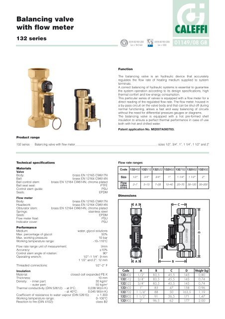
132 series <strong>Balancing</strong> <strong>valve</strong> <strong>with</strong> <strong>flow</strong> <strong>meter</strong> sizes 1/2”, 3/4”, 1”, 1 1/4”, 1 1/2” and 2”<br />
Technical specifications<br />
Materials<br />
Valve<br />
Body: brass EN 12165 CW617N<br />
Ball: brass EN 12164 CW614N<br />
Ball control stem: brass EN 12164 CW614N, chrome plated<br />
Ball seal seat: PTFE<br />
Control stem guide: PSU<br />
Seals:<br />
Flow <strong>meter</strong><br />
EPDM<br />
Body: brass EN 12165 CW617N<br />
Headwork: brass EN 12164 CW614N<br />
Obturator stem: brass EN 12164 CW614N, chrome plated<br />
Springs: stainless steel<br />
Seals: EPDM<br />
Flow <strong>meter</strong> float: PSU<br />
Indicator cover:<br />
Performance<br />
PSU<br />
Medium: water, glycol solutions<br />
Max. percentage of glycol: 50%<br />
Max. working pressure: 10 bar<br />
Working temperature range: -10–110°C<br />
Flow rate range unit of measurement: l/min<br />
Accuracy: ±10%<br />
Control stem angle of rotation: 90°<br />
Operating wrench: 1/2”–1 1/4”: 9 mm<br />
1 1/2” and 2”: 12 mm<br />
Threaded connections:<br />
Insulation<br />
1/2”–2” F<br />
Material: closed cell expanded PE-X<br />
Thickness: 10 mm<br />
Density: - inner part: 30 kg/m3 - outer part: 50 kg/m3 Thermal conductivity (DIN 52612): - at 0°C: 0,038 W/(m·K)<br />
- at 40°C: 0,045 W/(m·K)<br />
Coefficient of resistance to water vapour (DIN 52615): > 1.300<br />
Working temperature range: 0–100°C<br />
Reaction to fire (DIN 4102): class B2<br />
REGI STERED BSI EN ISO 9001:2000<br />
Dimensions<br />
Code<br />
132402<br />
132512<br />
132522<br />
132602<br />
132702<br />
132802<br />
132902<br />
Cert. n° FM 21654<br />
Flow rate ranges<br />
A<br />
CALEFFI<br />
15<br />
bar<br />
7<br />
6<br />
5<br />
4<br />
3<br />
2<br />
A B<br />
A<br />
1/2”<br />
3/4”<br />
3/4”<br />
1”<br />
1 1/4”<br />
1 1/2”<br />
2”<br />
UNI EN ISO 9001:2000<br />
Cert. n° 0003<br />
Code 132402 132512 132522 132602 132702 132802 132902<br />
Size 1/2” 3/4” 3/4” 1” 1 1/4” 1 1/2” 2”<br />
Flow<br />
rates<br />
(l/min)<br />
2–7 5–13 7–28 10–40 20–70 30–120 50–200<br />
B<br />
83,5<br />
83,5<br />
83,5<br />
85<br />
88<br />
91<br />
96,5<br />
C<br />
45,5<br />
45,5<br />
45,5<br />
47<br />
50<br />
56,5<br />
62<br />
C<br />
D<br />
145<br />
145<br />
145<br />
158<br />
163,5<br />
171<br />
177<br />
D<br />
Weight (kg)<br />
0,80<br />
0,74<br />
0,74<br />
0,96<br />
1,19<br />
1,47<br />
2,00
Advantages of balanced circuits<br />
Balanced circuits have the following principal benefits:<br />
1. The system terminals operate correctly in heating, cooling and<br />
dehumidification <strong>with</strong>out waste of energy and provide a better<br />
comfort.<br />
2. The pumps run in their zone of highest efficiency, thus reducing<br />
the risk of overheating and excessive wear.<br />
3. Too high medium speeds, which can result in noise and<br />
abrasion, are avoided.<br />
4. The differential pressures acting on the regulation <strong>valve</strong>s are<br />
limited in value, thus preventing faulty operation.<br />
Construction details<br />
Flow <strong>meter</strong><br />
The <strong>flow</strong> rate value is displayed<br />
directly by a <strong>flow</strong> <strong>meter</strong> housed<br />
in a by-pass circuit on the <strong>valve</strong><br />
body, automatically shut-off<br />
during normal functioning.<br />
The use of a <strong>flow</strong> <strong>meter</strong> greatly<br />
simplifies the process of system<br />
balancing, since the <strong>flow</strong> rate<br />
can be measured and<br />
controlled at any time and there<br />
is no need for differential<br />
pressure gauges or reference<br />
charts.<br />
The provision of a <strong>flow</strong> <strong>meter</strong><br />
also means that it is not<br />
anymore necessary to calculate<br />
<strong>valve</strong> settings at the system<br />
design stage.<br />
The advantages of this solution<br />
can be explained as significant<br />
time and cost saving, because<br />
the traditional balancing device<br />
presetting, performed by<br />
qualified technicians, is a long<br />
and difficult procedure.<br />
7<br />
6<br />
5<br />
4<br />
3<br />
2<br />
2<br />
3<br />
4<br />
5<br />
6<br />
7<br />
2<br />
3<br />
4<br />
5<br />
6<br />
7<br />
2<br />
Operating principle<br />
The balancing <strong>valve</strong> is an hydraulic device that allows to regulate<br />
the medium <strong>flow</strong> rate passing through.<br />
The regulating action is made by a ball obturator (1), operated by<br />
a control stem (2). The <strong>flow</strong> rate is controlled by means of a <strong>flow</strong><br />
<strong>meter</strong> (3) housed in a by-pass circuit, on the <strong>valve</strong> body, that can<br />
be shut off during normal functioning. The <strong>flow</strong> rate value is<br />
indicated by a metal sphere (4), sliding <strong>with</strong>in a transparent guide<br />
(5), marked alongside by a graduated scale (6).<br />
Flow <strong>meter</strong> obturator<br />
The obturator (1) opens and shuts the circuit between the <strong>flow</strong><br />
<strong>meter</strong> and the <strong>valve</strong>. The obturator can be easily opened by pulling<br />
the ring (2), and is closed automatically, after completion of the<br />
procedure, by theinternal spring (3). The spring and the EPDM seal<br />
(4) guarantee over time a perfect circuit closure during normal<br />
functioning.<br />
The operating ring (2) is made of a material <strong>with</strong> low thermal<br />
conductivity to avoid burns if the <strong>flow</strong> <strong>meter</strong> is opened while hot<br />
medium is passing through the <strong>valve</strong>.<br />
Ball/magnet indicator<br />
The ball (4) that indicates the <strong>flow</strong> rate value is<br />
not in direct contact <strong>with</strong> the thermal medium<br />
passing through the <strong>flow</strong> <strong>meter</strong>.<br />
Thanks to an effective and innovative measuring<br />
system, the ball slides up and down in a cylinder<br />
(5) that is actually separate from the body of the<br />
<strong>flow</strong> <strong>meter</strong>. The ball is moved by a magnet (6)<br />
fixed to a float (7).<br />
This means that the <strong>flow</strong> rate indication system<br />
remains perfectly clean and provides reliable<br />
readings over time.<br />
4<br />
3<br />
1<br />
2<br />
3<br />
5<br />
4<br />
15<br />
1<br />
1<br />
2<br />
7<br />
6<br />
5<br />
4<br />
3<br />
2<br />
3<br />
5<br />
6<br />
4<br />
5<br />
7<br />
6<br />
4
Complete closing and opening of the <strong>valve</strong><br />
The <strong>valve</strong> can be completely closed and opened.<br />
A slot on the obturator stem indicates the status of the <strong>valve</strong>.<br />
When the control stem<br />
is turned fully clockwise Completely closed Completely open<br />
and the slot lies<br />
perpendicular to the<br />
axis of the <strong>valve</strong>, the<br />
<strong>valve</strong> is fully closed (A).<br />
When the control<br />
stem is turned fully<br />
anti-clockwise and the<br />
slot lies parallel to the<br />
axis of the <strong>valve</strong>, the<br />
<strong>valve</strong> is fully open (B).<br />
A B<br />
Hydraulic characteristics<br />
Δp (mm w.g.)<br />
15.000<br />
10.000<br />
5.000<br />
2.000<br />
1.000<br />
500<br />
200<br />
100<br />
50 100<br />
250 500 1.000 2.500 5.000 10.000 25.000<br />
Code 132402 132512 132522 132602 132702 132802 132902<br />
Size 1/2” 3/4” 3/4” 1” 1 1/4” 1 1/2” 2”<br />
Flow<br />
rates<br />
(l/min)<br />
2–7 5–13 7–28 10–40 20–70 30–120 50–200<br />
Kv (m 3 /h) 0,9 2,5 5,4 7,2 13,1 27,8 46,4<br />
Kv <strong>valve</strong>s fully open<br />
Correction for liquids <strong>with</strong> different densities<br />
1/2”<br />
Δp (kPa)<br />
1<br />
50.000<br />
G (l/h)<br />
For fluids <strong>with</strong> a viscosity ≤3°E, e.g. water/glycol solutions <strong>with</strong> density<br />
different <strong>with</strong> respect to the water at 20°C (ρ = 1 kg/dm 3 ), to which the<br />
upper diagram refers, it should be considered that:<br />
- pressure drop (for sizing the pump) is determined by:<br />
Δpactual = Δpreference x ρglycol solution;<br />
- variation in <strong>flow</strong> rate measurement remains <strong>with</strong>in the specified<br />
accuracy (±10%) for glycol percentages up to 50%.<br />
Installation<br />
Install the balancing <strong>valve</strong> in such a way to ensure free access to<br />
the <strong>flow</strong> <strong>meter</strong> obturator, control stem and <strong>flow</strong> rate indicator.<br />
We recommend to install straight sections of pipe as shown in the<br />
illustration below to ensure accurate <strong>flow</strong> measurement.<br />
7<br />
6<br />
5<br />
4<br />
3<br />
2<br />
132 series 132 series<br />
5D<br />
7<br />
6<br />
5<br />
4<br />
3<br />
2<br />
3/4”<br />
2<br />
3<br />
4<br />
3/4”<br />
5<br />
6<br />
7<br />
1”<br />
1 1/4”<br />
1 1/2”<br />
10D<br />
2”<br />
Pump<br />
The <strong>valve</strong> can be installed in any position by respecting the <strong>flow</strong><br />
direction shown on the <strong>valve</strong> body. The <strong>valve</strong> can be installed either<br />
horizontally or vertically.<br />
7<br />
6<br />
5<br />
4<br />
3<br />
2<br />
150<br />
100<br />
50<br />
20<br />
10<br />
5<br />
2<br />
Insulation<br />
The 132 series balancing <strong>valve</strong><br />
is supplied complete <strong>with</strong> hot<br />
pre-formed insulation. This<br />
system ensures not only perfect<br />
thermal insulation, but also<br />
tightness to water vapour from<br />
the environment towards the<br />
inside. For these reasons, this<br />
type of insulation can also be<br />
used in chilled water circuits as<br />
it prevents condensation<br />
forming on the surface of the<br />
<strong>valve</strong> body.<br />
Flow rate adjustment<br />
The <strong>flow</strong> rate is adjusted by carrying out the following operations:<br />
A.With the aid of the indicator<br />
(1), mark the reference <strong>flow</strong><br />
rate at which the <strong>valve</strong> has to<br />
be set.<br />
1<br />
B.Use the ring (2) to open the<br />
obturator that shuts off the<br />
<strong>flow</strong> of medium in the <strong>flow</strong><br />
<strong>meter</strong> (3) under normal<br />
operating conditions.<br />
C.Keeping the obturator open, apply a wrench on the control stem<br />
of the <strong>valve</strong> (4) to adjust the <strong>flow</strong> rate. It is indicated by a metal<br />
ball (5) that runs inside a transparent guide (6) marked by a<br />
graduated scale in l/min.<br />
4<br />
D.After completing the balancing, release the ring of the <strong>flow</strong> <strong>meter</strong><br />
obturator that, thanks to an internal spring, will automatically go<br />
back into the closed position.<br />
5<br />
6<br />
3<br />
2
Application diagrams<br />
The balancing <strong>valve</strong> <strong>with</strong> the <strong>flow</strong> <strong>meter</strong> should preferably be installed on the circuit return pipe.<br />
To adjust the <strong>flow</strong> rate to each riser<br />
To adjust the <strong>flow</strong> rate to each terminal<br />
SPECIFICATION SUMMARIES<br />
To balance circuits serving air conditioning units<br />
To balance zone branches in circuits <strong>with</strong> three-way <strong>valve</strong>s To balance sanitary water distribution circuits<br />
132 series<br />
<strong>Balancing</strong> <strong>valve</strong> <strong>with</strong> <strong>flow</strong> <strong>meter</strong>. Threaded connections 1/2” (from 1/2” to 2”) F x F. Brass body. Brass ball. Brass ball control<br />
stem, chrome plated. PTFE ball seal seat. PSU control stem guide. Brass <strong>flow</strong> <strong>meter</strong> body and headwork. Brass <strong>flow</strong> <strong>meter</strong><br />
obturator control stem, chrome plated. Stainless steel <strong>flow</strong> <strong>meter</strong> springs. PSU <strong>flow</strong> <strong>meter</strong> float and indicator cover. EPDM<br />
seals. With pre-formed shell insulation in expanded closed cell PE-X. Medium water and glycol solutions. Maximum<br />
percentage of glycol 50%. Maximum working pressure 10 bar. Working temperature range -10–110°C. Flow rate range unit of<br />
measurement l/min. Accuracy ± 10%. Control stem angle of rotation 90°.<br />
We reserve the right to make changes and improvements to the products and related data in this publication, at any time and <strong>with</strong>out prior notice.<br />
CALEFFI<br />
CALEFFI S.P.A. · I · 28010 FONTANETO D’AGOGNA (NO) · S.R. 229, N.25 · TEL. +39 0322 8491 R.A. · FAX +39 0322 863723<br />
· www.caleffi.com · info@caleffi.com ·<br />
© Copyright 2008 <strong>Caleffi</strong><br />
s<br />
To balance the by-pass branch of outside compensated<br />
control circuits


