

Safety relief valve for solar systems - Caleffi
Safety relief valve for solar systems - Caleffi
Safety relief valve for solar systems - Caleffi

You also want an ePaper? Increase the reach of your titles
YUMPU automatically turns print PDFs into web optimized ePapers that Google loves.
<strong>Safety</strong> <strong>relief</strong> <strong>valve</strong> <strong>for</strong> <strong>solar</strong> <strong>systems</strong><br />
253 series<br />
Product range<br />
cert. n° 0003<br />
ISO 9001<br />
CALEFFI<br />
01089/06 GB<br />
Replaces 01089/03 GB<br />
General<br />
The safety <strong>relief</strong> <strong>valve</strong>s manufactured by <strong>Caleffi</strong> are produced in<br />
compliance with the essential safety requirements laid down by<br />
Directive 97/23/EC of the European Parliament and the Council of<br />
the European Union <strong>for</strong> the harmonisation of member States with<br />
regard to pressurised equipment.<br />
Function<br />
These safety <strong>relief</strong> <strong>valve</strong>s are used to control pressure in the<br />
primary circuits of <strong>solar</strong> heating <strong>systems</strong>.<br />
When the calibrated pressure is reached, the <strong>valve</strong> opens to<br />
release the fluid into the atmosphere and prevents the pressure in<br />
the system from reaching levels that might damage the <strong>solar</strong><br />
collectors and equipment installed.<br />
These particular series of products have been specially made and<br />
certified to work at high temperature with a glycol medium.<br />
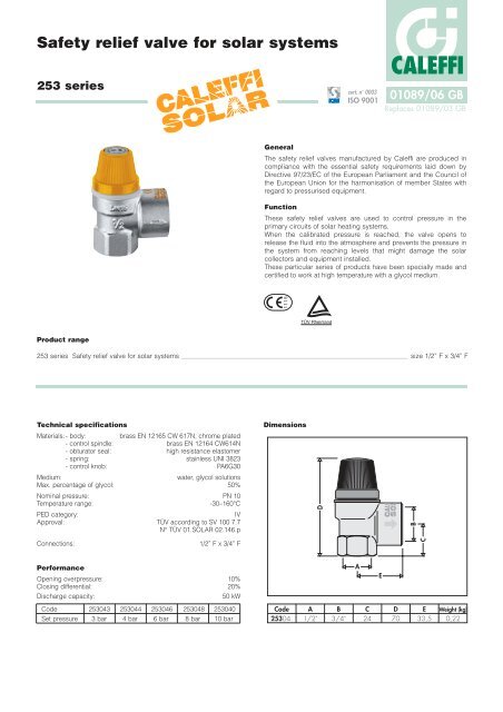
253 series <strong>Safety</strong> <strong>relief</strong> <strong>valve</strong> <strong>for</strong> <strong>solar</strong> <strong>systems</strong> size 1/2” F x 3/4” F<br />
Technical specifications<br />
Materials: - body: brass EN 12165 CW 617N, chrome plated<br />
- control spindle: brass EN 12164 CW614N<br />
- obturator seal: high resistance elastomer<br />
- spring: stainless UNI 3823<br />
- control knob: PA6G30<br />
Medium: water, glycol solutions<br />
Max. percentage of glycol: 50%<br />
Nominal pressure: PN 10<br />
Temperature range: -30–160°C<br />
PED category: IV<br />
Approval: TÜV according to SV 100 7.7<br />
N° TÜV 01.SOLAR 02.146.p<br />
Connections: 1/2” F x 3/4” F<br />
Per<strong>for</strong>mance<br />
Opening overpressure: 10%<br />
Closing differential: 20%<br />
Discharge capacity: 50 kW<br />
Code 253043 253044 253046 253048 253040<br />
Set pressure 3 bar 4 bar 6 bar 8 bar 10 bar<br />
1115<br />
Dimensions<br />
Code<br />
25304.<br />
D<br />
A<br />
1/2"<br />
B<br />
3/4"<br />
A<br />
C<br />
24<br />
E<br />
D<br />
70<br />
B<br />
C<br />
E<br />
33,5<br />
Weight (kg)<br />
0,22
Operating principe<br />
The obturator (1), opposed by a<br />
set spring (2), raises on reaching<br />
the setting pressure and fully<br />
opens the outlet. The setting<br />
pressure is chosen according to<br />
the maximum permissible<br />
pressure in the system.<br />
The diameter of the outlet<br />
connection (3) is greater in order<br />
to help discharge the required<br />
potential.<br />
As the pressure decreases there<br />
is the opposite action, with the<br />
<strong>valve</strong> subsequently reclosing<br />
within the set tolerances.<br />
Construction details<br />
Temperature and glycol<br />
In <strong>solar</strong> <strong>systems</strong>, heating fluid of the primary circuit contains glycol<br />
as additive and operates at high temperatures; to take account of<br />
these particular operating conditions, the obturator seal of safety<br />
<strong>valve</strong> is in high resistance elastomer.<br />
The knob is in plastic material especially resistant to increases in<br />
temperature and to UV rays, in the case of outdoor installations.<br />
Chrome plating<br />
The <strong>valve</strong> body is chrome plated to protect it from the aggression<br />
of dirt and moisture, in the case of outdoor installations of <strong>solar</strong><br />
heating <strong>systems</strong>.<br />
Certification<br />
253 series safety <strong>relief</strong> <strong>valve</strong>s are certified <strong>for</strong> specific use in <strong>solar</strong><br />
heating <strong>systems</strong> by the certifying body TÜV, in accordance with<br />
standard SV 100 Ed. 10.01 par. 7.7.<br />
Installation<br />
The safety <strong>relief</strong> <strong>valve</strong>s <strong>for</strong> <strong>solar</strong> <strong>systems</strong> must be installed near the<br />
point in the circuit where the system is filled, be<strong>for</strong>e expansion<br />
vessel.<br />
Make sure that there are no shut-off devices between the <strong>valve</strong> and<br />
the rest of the system.<br />
The safety <strong>relief</strong> <strong>valve</strong>s can be fitted vertically or horizontally, but<br />
not upside down.<br />
This prevents deposits of impurities from affecting correct<br />
functioning.<br />
The safety <strong>relief</strong> <strong>valve</strong>s must be installed in line with the flow<br />
direction indicated by the arrow on the <strong>valve</strong> body.<br />
2<br />
1<br />
3<br />
SPECIFICATION SUMMARIES<br />
Discharge pipework<br />
The discharge pipework from the safety <strong>relief</strong> <strong>valve</strong> must be fitted<br />
in such a way as not to prevent the correct operation of the <strong>valve</strong><br />
and not to cause damage or injury.<br />
In accordance with current legislation, the safety <strong>relief</strong> <strong>valve</strong><br />
discharge must be visible and<br />
carried in suitable collection<br />
pipework. The glycol medium must<br />
there<strong>for</strong>e be drained off into a<br />
specific container.<br />
As shown in the diagram, it is<br />
advisable to install a tundish<br />
direcly in the discharge pipework.<br />
Application diagram<br />
253 series<br />
<strong>Safety</strong> <strong>relief</strong> <strong>valve</strong> <strong>for</strong> <strong>solar</strong> heating <strong>systems</strong>. CE mark as per Directive 97/23/EC. TÜV certified <strong>for</strong> <strong>solar</strong> <strong>systems</strong>. 1/2” F x 3/4” F<br />
threaded connections. Brass body. Chrome plated. Diaphragm and obturator seal in high resistance elastomer. Spring in steel<br />
UNI 3823. Control knob in PA6G30. Temperature range: -30–160°C. Nominal pressure: PN 10. Calibration setting: 3 bar<br />
(3, 4, 6, 8, 10 bar). Medium: water and glycol solutions. Maximum percentage of glycol: 50%.<br />
We reserve the right to change our products and their relevant technical data, contained in this publication, at any time and without prior notice.<br />
CALEFFI<br />
CALEFFI S.P.A. · I · 28010 FONTANETO D’AGOGNA (NO) · S.R. 229, N.25 · TEL. +39 0322 8491 R.A. · FAX +39 0322 863723<br />
· Http://www.caleffi.com · E-mail: info@caleffi.it ·


