Delta Cooling Towers, Inc. Paragon Induced Draft Cooling Tower
Delta Cooling Towers, Inc. Paragon Induced Draft Cooling Tower
Delta Cooling Towers, Inc. Paragon Induced Draft Cooling Tower

You also want an ePaper? Increase the reach of your titles
YUMPU automatically turns print PDFs into web optimized ePapers that Google loves.
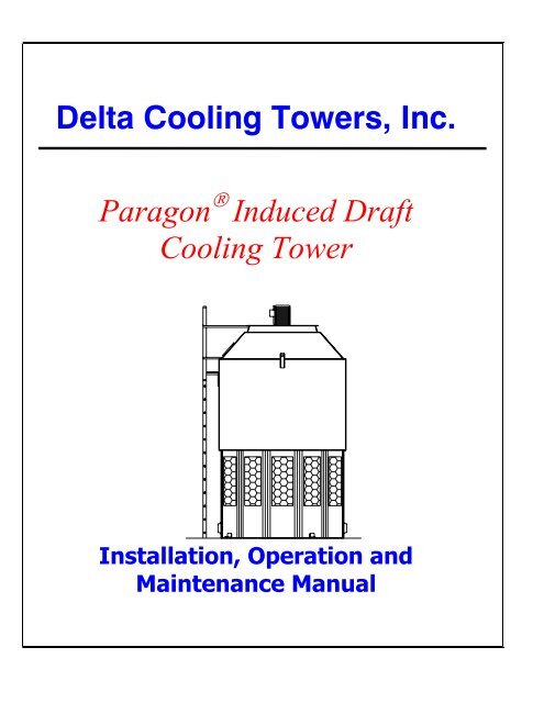
<strong>Delta</strong> <strong>Cooling</strong> <strong><strong>Tower</strong>s</strong>, <strong>Inc</strong>.<br />
<strong>Paragon</strong> ® <strong>Induced</strong> <strong>Draft</strong><br />
<strong>Cooling</strong> <strong>Tower</strong><br />
Installation, Operation and<br />
Maintenance Manual
Table of Contents<br />
<strong>Delta</strong> <strong>Cooling</strong> <strong><strong>Tower</strong>s</strong> Principle of <strong>Cooling</strong> <strong><strong>Tower</strong>s</strong>………………..……………. 1<br />
<strong>Cooling</strong> <strong>Tower</strong> Terms and Definitions…………………… 1<br />
Water Treatment……..………………………….……….. 1<br />
General Information Safety………………..………………………………….… 2<br />
Approximate Weights………………..…………………… 2<br />
Dimensions & Other Physical Data……..………...……… 2<br />
Handling & Installation On-Site Inspection………………..………..…….….……. 2<br />
Off Loading……..……………..………………………….. 2<br />
Handling & Off Loading - Fig. 1…………………………. 2<br />
Uprighting & Lifting of <strong>Cooling</strong> <strong>Tower</strong>……..………...….. 3<br />
Anchoring……..……….…………………………..……… 3<br />
Water Distribution System/ <strong>Tower</strong> InternalsPre-Check…... 3<br />
Water Distribution Sprinkler System – Fig 2……………… 3<br />
Lifting & Installation of the Fan Assembly……………….. 4<br />
Electrical Wiring of Fan Motor & Accessories……..…….. 4<br />
Location, Piping & Connections……..…….……….…….. 4<br />
PVC Solvent Cementing Instructions………………...…… 5<br />
Operation and Maintenance Safety in Operation of the Fan..…..………..…….….……. 5<br />
Water Distribution System……..…………………………. 5<br />
Sprinkler Head Maintenance……….……………..………. 6<br />
Optional Sray Nozzle Distribution System………………. 6<br />
Direct Drive Fan Assembly ……….………………..…...… 6<br />
Start-up Instructions………………………………..…….. 7<br />
Water Level in <strong>Tower</strong> Sump…..……..…….……….…….. 7<br />
Cold Weather Operation…………...………………...…… 7<br />
Trouble-Shooting Guide.…………...……………….….… 9<br />
Motor Trouble-Shooting Guide…………...………....…… 11<br />
Other Information <strong>Cooling</strong> <strong>Tower</strong> Optional Accessories..…..…...….….……. 12<br />
Recommended Replacement Parts……..…………………. 12<br />
Appendices (Reference Documents)……………..……….. 12<br />
Preventative Maintenance Checklist….……………….….. 13<br />
Warranty…………..………………………………..…….. 14<br />
Important:<br />
<strong>Delta</strong>’s cooling towers have been designed to provide trouble-free service over an extended period of time.<br />
To obtain the design performance, it is necessary that the cooling tower be installed, operated and<br />
maintained as prescribed in these instructions.<br />
Only persons possessing the skill and experience described herein should attempt to install this equipment.<br />
Prior to installation, these instructions should be read carefully by the person who is to install the<br />
cooling tower to be certain that its installation, operation and maintenance are thoroughly understood.<br />
Questions regarding the installation, operation or maintenance of this equipment should be directed to <strong>Delta</strong><br />
<strong>Cooling</strong> <strong><strong>Tower</strong>s</strong>, <strong>Inc</strong>., Rockaway, New Jersey, (Telephone: 973/586-2201).<br />
Step-by-step instructions contained in this brochure are based on normal installation conditions only.<br />
Abnormal or unusual combinations of field conditions should be brought to the attention of <strong>Delta</strong> <strong>Cooling</strong><br />
<strong><strong>Tower</strong>s</strong> or its representative prior to installation of the equipment. The information contained herein is<br />
subject to change without notice in the interest of product improvement.<br />
Rev. 1-2-2008
<strong>Delta</strong> <strong>Cooling</strong> <strong><strong>Tower</strong>s</strong><br />
Principle of <strong>Cooling</strong> <strong><strong>Tower</strong>s</strong><br />
All <strong>Cooling</strong> <strong><strong>Tower</strong>s</strong> operate on the<br />
principle of removing heat from water<br />
by evaporating a small portion of the<br />
water that is recirculated through the<br />
unit.<br />
The heat that is removed is called the<br />
latent heat of vaporization.<br />
Each one pound of water that is<br />
evaporated removes approximately<br />
1,000 BTU's in the form of latent heat.<br />
<strong>Cooling</strong> <strong>Tower</strong> Terms and<br />
Definitions<br />
BTU - A BTU is the heat energy<br />
required to raise the temperature of one<br />
pound of water one degree Fahrenheit<br />
in the range from 32° F. to 212° F.<br />
<strong>Cooling</strong> Range - The difference in<br />
temperature between the hot water<br />
entering the tower and the cold water<br />
leaving the tower is the cooling range.<br />
Approach - The difference between the<br />
temperature of the cold water leaving<br />
the tower and the wet-bulb temperature<br />
of the air is known as the approach. The<br />
approach fixes the operating<br />
temperature of the tower and is a most<br />
important parameter in determining<br />
both tower size and cost.<br />
Drift - The water entrained in the air<br />
flow and discharged to the atmosphere.<br />
Drift loss does not include water lost by<br />
evaporation. Proper tower design and<br />
operation can minimize drift loss.<br />
Heat Load - The amount of heat to<br />
be removed from the circulating water<br />
within the tower. Heat load is equal to<br />
water circulation rate (gpm) times the<br />
cooling range times 500 and is<br />
expressed in BTU/hr. Heat load is also<br />
an important parameter in determining<br />
tower size and cost.<br />
Ton - An evaporative cooling ton is<br />
15,000 BTU's per hour.<br />
Wet-Bulb Temperature - The lowest<br />
temperature that water theoretically can<br />
reach by evaporation. Wet-Bulb<br />
Temperature is an extremely important<br />
parameter in tower selection and design<br />
and should be measured by a<br />
psychrometer.<br />
Pumping Head - The pressure<br />
required to pump the water from the<br />
tower basin, through the entire system<br />
and return to the cooling tower.<br />
Make-Up - The amount of water<br />
required to replace normal losses caused<br />
by bleed-off, drift, and evaporation.<br />
Bleed Off (Blowdown) - The<br />
circulating water in the tower, which is<br />
discharged to waste to help keep the<br />
dissolved solids concentration of the<br />
water below a maximum allowable limit.<br />
As a result of evaporation, dissolved<br />
solids concentration will continually<br />
increase unless reduced by bleed off.<br />
Water Treatment<br />
• <strong>Delta</strong>’s <strong>Cooling</strong> <strong><strong>Tower</strong>s</strong> are<br />
fabricated of non-corrosive engineered<br />
plastics which are resistant to water<br />
treatment chemicals including common<br />
fungicides and bactericides.<br />
• Follow appropriate water treatment<br />
practices such as required and take<br />
frequent sample tests to avoid<br />
possible water contamination. We<br />
also recommend water treatment<br />
maintenance as a measure of<br />
protection for the environment in<br />
the vicinity of any cooling tower or<br />
other equipment open to<br />
atmosphere.<br />
• To determine the appropriate<br />
water treatment practices for your<br />
particular application, it is<br />
suggested that you contact a local<br />
water treatment firm for their<br />
recommendation.<br />
• Bleed-off is also important to water<br />
quality. Evaporation of the<br />
recirculated water does not remove<br />
the dissolved solids that are<br />
present in the water. Without<br />
bleed-off, the continual buildup of<br />
these solids will impair the proper<br />
functioning of the equipment in the<br />
system.<br />
• A bleed line can be connected in<br />
any part of the system with routing<br />
to the sewer. Normally, it is most<br />
desirable to make this connection<br />
in the hot water line at the cooling<br />
tower. A petcock type valve,<br />
installed in the bleed line is<br />
recommended. Normally, bleed-off<br />
of 1% to 2% of the recirculation<br />
water flow is satisfactory. The<br />
required amount of bleed-off water<br />
must be replaced with properly<br />
controlled amounts of make-up<br />
water.<br />
1
General Information<br />
Safety<br />
When handling, lifting, installing or<br />
operating the cooling tower, always<br />
employ safe work procedures according<br />
to best practices of the trade and<br />
according to applicable construction,<br />
electrical and safety standards,<br />
regulations and codes.<br />
Approximate Weights<br />
The induced draft cooling towers are<br />
manufactured in two basic sections; a<br />
polyethylene tower body and a fan<br />
assembly section. Both of these sections<br />
are factory assembled and packaged<br />
separately for field installation.<br />
Dimensions and Other Physical<br />
Data<br />
For cooling tower dimensions, design for<br />
foundations, assembly and layout; refer<br />
to the following drawings, which are a<br />
part of these instructions:<br />
Follow all safety practices<br />
described in these instructions.<br />
Overall<br />
Approximate Weights (lbs.)<br />
Dimensions<br />
(inch)<br />
Model # Shipping Operating W x L x H<br />
∆T-55I<br />
∆T-70I<br />
∆T-85I<br />
∆T-100I<br />
∆T-125I<br />
∆T-150I<br />
∆T-175I<br />
1,180<br />
1,250<br />
1,270<br />
1,510<br />
1,585<br />
1,785<br />
1,925<br />
3,980<br />
4,050<br />
4,070<br />
4,235<br />
4,310<br />
5,570<br />
5,810<br />
84 x 146<br />
84 x 146<br />
84 x 146<br />
84 x 146<br />
84 x 146<br />
95 x 179<br />
95 x 179<br />
Model # Title Drawing No.<br />
∆T-55I, ∆T-<br />
70I<br />
&<br />
Assembly<br />
Layout<br />
DT-D-81-756<br />
DT-D-81-755<br />
∆T-85I<br />
∆T-100I<br />
&<br />
∆T-125I<br />
Assembly<br />
Layout<br />
DT-D-81-754<br />
DT-D-81-755<br />
∆T-150I<br />
&<br />
∆T-175I<br />
Assembly<br />
Layout<br />
DT-D-83-754<br />
DT-D-83-755<br />
∆T-200I<br />
&<br />
∆T-250I<br />
Assembly<br />
Layout<br />
DT-D-80-754<br />
DT-D-80-755<br />
NOTE: Elevation of the center of<br />
gravity of the tower body (without fan<br />
assembly) is approximately at<br />
the top of the ribs.<br />
∆T-200I<br />
3,170<br />
8,355<br />
114 x 218<br />
∆T-250I<br />
3,365<br />
8,500<br />
114 x 218<br />
together with shipping skid.<br />
Handling and Installation of Your <strong>Paragon</strong> ® <strong>Cooling</strong> <strong>Tower</strong><br />
On -Site Inspection<br />
Upon arrival at the job site, carefully<br />
inspect the shipment for any damage. If<br />
shipping damage has occurred, notify<br />
the driver or the carrier immediately in<br />
writing of all damage. Check that all<br />
items listed on the Shipping Bill of<br />
Lading have been received.<br />
Offloading (see Figure 1)<br />
The ∆T-200/250I cooling towers are<br />
normally delivered to the site on a “low<br />
boy” or “drop deck” trailer. The ∆T-<br />
55/70/85/100/125/150/175I cooling<br />
towers are normally shipped in a<br />
closed van, and can be off-loaded by<br />
fork truck. The tower body is shipped<br />
strapped down on a skid. The fan<br />
assembly with motor is crated<br />
separately. Unload the tower body<br />
Figure 1 -<br />
Offloading<br />
2
Lifting with crane:<br />
• Before lifting, inspect skid and<br />
banding material and align or repair, if<br />
necessary.<br />
• Use fabric slings of sufficient<br />
strength for better load distribution<br />
and protection of the plastic tower<br />
body. Pass slings around the tower body<br />
itself. (This procedure should not be<br />
used for high or extended lifts unless<br />
the<br />
skid is secured to the tower body with<br />
additional strapping).<br />
• Locate the slings of sufficient<br />
strength for better load distribution and<br />
protection of the plastic tower body.<br />
Pass slings around the tower body itself.<br />
(This procedure should not be used for<br />
high or extended lifts unless the skid is<br />
secured to the tower body with<br />
additional strapping).<br />
• Use a spreader bar or crane boom<br />
with adequate length straps in order to<br />
maintain an angle of 60° or less<br />
between slings.<br />
Offloading with fork truck:<br />
• A fork truck of sufficient<br />
capacity may be used for offloading.<br />
The forks should pass under the skid<br />
along the length of the tower body with<br />
the tips of the fork extensions passing<br />
under the middle saddle of the skid, or<br />
bearing on fork tip supports where they<br />
are provided. A strap should be placed<br />
around the tower body and forks to<br />
secure the load.<br />
• Fork extensions (about 10 ft.<br />
long) are necessary for models ∆T-<br />
200/250I tower skids.<br />
Store the fan assembly with all shipping<br />
padding or bracing in place on the<br />
shipping skid in a secure location at the<br />
job site until the time of installation.<br />
After offloading, store the tower body<br />
upright.<br />
CAUTION: For extended lifts, use<br />
duplicate rigging as an additional safety<br />
precaution.<br />
Uprighting and Lifting of <strong>Cooling</strong><br />
<strong>Tower</strong><br />
purposes. Install adequate hooks and<br />
cable to each of these lifting lugs, lift the<br />
cooling tower upright and set it on a<br />
smooth, flat and rigid surface. Use guide<br />
lines as necessary, to prevent damage<br />
to the cooling tower, and as a safety<br />
measure to control and avoid sudden<br />
shifts or movements of the load.<br />
• IMPORTANT: For extended lifts<br />
over 25 feet in height, use fabric slings<br />
underneath the cooling tower and<br />
secure them at the lifting lug location,<br />
as an additional safety precaution.<br />
Remove air inlet louvers, as necessary,<br />
to prevent their damage during<br />
handling.<br />
• After re-checking the rigging, lift<br />
the tower body and set in place on the<br />
previously prepared foundation. Use<br />
guide lines, as necessary, to stabilize the<br />
load.<br />
• Remove the strut supports<br />
attached<br />
to the top of the tower and all padding<br />
or packaging inside the tower. The<br />
shipping supports on top of the fill<br />
media, as well as other packaging, may<br />
be removed through the inspection port<br />
in the side of the cooling tower.<br />
• Replace previously removed<br />
louvers.<br />
CAUTION: When working inside the<br />
cooling tower where the sprinkler<br />
system is located, DO NOT step directly<br />
on the fill. Use two (2) pieces of 3/8”<br />
minimum thickness plywood each at<br />
least 12” X 18” to distribute the worker’s<br />
weight in order to prevent damage to<br />
the fill.<br />
Anchoring<br />
The foundation must be flat, smooth<br />
and rigid enough to be capable of<br />
independent support of the cooling<br />
tower assembly and water load in the<br />
sump at it's maximum level. (Refer to<br />
Dimensions and Other Physical Data.)<br />
• Four hold-down lugs are provided<br />
at the base of the tower with predrilled<br />
holes for anchor bolts.<br />
• Final location of anchor bolts<br />
should be matched with hold down<br />
lugholes at time of installation.<br />
• Use ¾” diameter anchor bolts<br />
(design pull-out load on one bolt is<br />
1,500 lbs. for wind loading).<br />
• Do not shim under the base of the<br />
tower to level.<br />
• If shimming of the anchor lug is<br />
required, the shim should extend from<br />
the bolt to the outside edge of anchor<br />
lug. Do not over tighten anchor nuts.<br />
• Check that all the hexagonal bolts<br />
on each lug are tight to prevent<br />
nuisance leaks. Access can be made by<br />
removing one of the air inlet PVC<br />
louvers.<br />
Water Distribution System / <strong>Tower</strong><br />
Internals Precheck<br />
Before installing the fan ring assembly:<br />
• Check to be sure all bracing,<br />
padding and shipping struts have been<br />
removed.<br />
• Install the sprinkler lateral arms,<br />
which were packaged separately. The<br />
center of the hexagonal bolt on the<br />
sprinkler head is at the center of the slot<br />
located on the sprinkler port. Care<br />
should be taken not to over-tighten the<br />
bolts, which lock the sprinkler lateral<br />
arms in place.<br />
• All four (4) sprinkler lateral arms,<br />
(see Figure 2), are normally shipped<br />
detached and are packaged and secure<br />
inside the tower. Remove these lateral<br />
arms before up-righting and lifting<br />
cooling tower.<br />
• Remove shipping skid straps.<br />
• Hooks and cables of sufficient<br />
strength should be used for lifting.<br />
• Two (2) aluminum lifting lugs<br />
secured to the top of the cylindrical<br />
section of the cooling tower are<br />
provided for uprighting and lifting<br />
Figure 2 – Water Distribution Sprinkler System<br />
3
• The drift eliminator blades are<br />
preassembled and do not require any<br />
adjustment. Simply check to be sure the<br />
hose clamps on each end of the lateral<br />
arms are tight. With the lateral arms<br />
installed, the drift eliminator blades<br />
should be parallel with the top of the fill<br />
(See Fig. 2).<br />
• Rotate the sprinkler system by<br />
hand to be sure it rotates freely.<br />
• Clean-out caps at the end of each<br />
lateral arm are in place and are secured<br />
with a fastener.<br />
The inspection port in the side of the<br />
cooling tower is provided to simplify<br />
certain of these check points and to<br />
facilitate flushing the sprinkler lateral<br />
arms when necessary.<br />
CAUTION: As described earlier, when<br />
stepping on top of fill, distribute body<br />
weight by means<br />
of two plywood plates.<br />
Lifting and Installation of the Fan<br />
Assembly<br />
• Break down fan crate, tip fan<br />
assembly, and set the fan ring on the<br />
ground before lifting.<br />
• It is recommended that a sealant<br />
caulking be placed all around the joint<br />
between the fan ring flange and tower<br />
shell.<br />
• Lift the fan assembly using the<br />
lifting lugs located on the fan ring.<br />
(Refer to Figure 3).<br />
• Align the yellow match mark on the<br />
fan assembly with the yellow match<br />
mark on the tower body.<br />
Note: If field piping, or equipment<br />
location dictates some other orientation,<br />
consult Factory. <strong>Delta</strong> can not be<br />
responsible for orientation other than<br />
standard, if variations were not known<br />
prior to shipment. Costs for field<br />
corrections will be the responsibilities of<br />
others, and may void equipment<br />
warranty if <strong>Delta</strong> approval is not<br />
obtained prior to any field changes.<br />
• Install eight (8) sets of fan<br />
assembly mounting hardware shipped<br />
loose with the tower. Use wide washers<br />
on the oversize holes in the tower<br />
flange. Do not tighten the self-locking<br />
nuts until all the bolts are in place.<br />
Some out-of-round distortion of the fan<br />
mounting flange at the top of the tower<br />
may be encountered. To match bolt<br />
holes, apply a radial force to the flexible<br />
tower body flange. A tapered alignment<br />
“drift” pin may be used.<br />
• Recheck the mounting hardware<br />
and tighten securely. Recommended<br />
torque value is 35 ft.-lbs.<br />
Electrical Wiring of Fan Motor and<br />
Accessories<br />
• Installation of a vibration cut-out<br />
switch is recommended. (Refer to tower<br />
accessories available).<br />
• All electrical work should be<br />
performed only by qualified personnel<br />
and in accordance to prevailing electrical<br />
codes, practices and safety standards.<br />
• The motor starter should be sized<br />
on voltage, nominal horsepower, and<br />
maximum full load current. This<br />
current value can be found on the<br />
nameplate. If the starter cannot accept<br />
the maximum full load motor current,<br />
the next size should be used.<br />
• Motor heaters should be selected<br />
on the basics of maximum full load<br />
current and service factors based on the<br />
motor nameplate.<br />
• Standard "<strong>Cooling</strong> <strong>Tower</strong> Service"<br />
motors are supplied with a minimum of<br />
a 1.15 Service Factor.<br />
• Optional two speed motors are<br />
single winding variable torque.<br />
• Run flexible conduit with some<br />
slack from the motor conduit box to<br />
terminal box outside the tower where<br />
rigid conduit can be used.<br />
• Conduit holding clip screws can be<br />
tapped directly into the tower wall. Use<br />
maximum 3/8" screws.<br />
• For the typical wiring schematic of<br />
fan motor and tower accessories, see<br />
<strong>Delta</strong> dwg. DT -B-78-001, included with<br />
these instructions.<br />
Location, Piping and Connections<br />
• Refer to the following drawings<br />
included with these instructions for<br />
recommended layout and pipe<br />
connection information.<br />
Model #<br />
∆T-55/85I<br />
∆T-100/125I<br />
∆T-150/175I<br />
∆T-200/250I<br />
Drawing No.<br />
DT-D-81-756<br />
DT-D-81-755<br />
DT-D-81-754<br />
DT-D-81-755<br />
DT-D-83-754<br />
DT-D-83-755<br />
DT-D-80-754<br />
DT-D-80-755<br />
• Piping should be adequately sized<br />
in accordance with accepted standard<br />
practices.<br />
• Gravity drain to indoor storage<br />
sump requires proper head differential<br />
and piping design considerations.<br />
Allowance must be made for flow, pipe<br />
size, piping layout and distance of<br />
cooling tower from the indoor storage<br />
sump.<br />
• On multiple tower installations,<br />
valving and/or pipe sizing should<br />
balance pressure drops to provide equal<br />
inlet pressures. Equalizing lines can be<br />
installed between cooling tower sumps<br />
and are available as an option from the<br />
factory. Each tower should be valved<br />
separately to allow for flow balancing or<br />
isolation from service.<br />
• Prior to start-up check that the PVC<br />
locknuts on all bulkhead fittings are<br />
properly tightened to prevent nuisance<br />
leaks. A chain wrench can be used to<br />
check and tighten the locknuts.<br />
• Check that the SS hexagonal nuts<br />
on the inlet and outlet PVC socket<br />
flanges are properly tightened to<br />
prevent nuisance leaks. While tightening<br />
the nuts, do not allow the bolt to rotate.<br />
This could damage the rubber seal<br />
under the flat washer on the bolt head<br />
located inside the cooling tower.<br />
• All supply and return piping must<br />
be independently supported.<br />
4
PVC Solvent Cementing<br />
Instructions<br />
The following procedure is<br />
recommended for the preparation and<br />
cementing of internal and external<br />
piping for <strong>Delta</strong> <strong>Cooling</strong> <strong><strong>Tower</strong>s</strong>:<br />
• Cut ends of pipe square using a<br />
handsaw and miter box. Tube cutters<br />
with wheels designed for use with PVC<br />
are acceptable, providing they do not<br />
leave a raised bead on the outside<br />
diameter of the pipe.<br />
• Use a chamfering tool or file to put<br />
a 10° to 15° chamfer on the end of the<br />
pipe. Lightly sand the area to be<br />
cemented to remove gloss. Using a<br />
clean rag, wipe pipe surface and fitting<br />
socket to remove dirt, moisture and<br />
grease. Acetone or similar solvent is<br />
recommended for cleaning.<br />
• Check " dry fit" of pipe and fitting<br />
by inserting pipe at least 1/3 of the way<br />
into the fitting. Position pipe and fitting<br />
to assure alignment. Pipe and fitting<br />
should be at same temperature<br />
condition.<br />
• Using a clean, natural bristle brush<br />
about 1/2 the size of the pipe diameter,<br />
apply a primer to the fitting socket.<br />
Apply primer with a scrubbing motion<br />
until the surface is penetrated. Primer<br />
should never be applied with a rag.<br />
Repeated applications may be necessary<br />
to achieve the desired dissolving action.<br />
In the same manner, apply primer to<br />
the pipe surface equal to the depth of<br />
the fitting socket; making sure the<br />
surface is well penetrated. Re-apply<br />
primer to the fitting socket to make sure<br />
it is still wet.<br />
• While both surfaces are still wet<br />
with primer, use a clean brush to apply<br />
a liberal coat of solvent cement to the<br />
male end of the pipe. The amount<br />
should be more than sufficient to fill any<br />
gap. Next apply a light coat of solvent<br />
cement to the inside of the socket, using<br />
straight outward strokes to keep excess<br />
cement out of the socket.<br />
• While both surfaces are still wet<br />
with solvent cement, insert the pipe into<br />
the socket with a quarter-turn twisting<br />
motion. The pipe must be<br />
inserted the full length of the<br />
socket. The application of solvent<br />
cement to pipe and fitting, and the<br />
insertion of the pipe into the fitting,<br />
should be completed in less than one<br />
minute. If necessary, two persons<br />
should apply solvent cement to the pipe<br />
and fitting simultaneously.<br />
• Hold the joint together for<br />
approximately 30 seconds until both<br />
surfaces are firmly gripped. After<br />
assembly, a properly made joint will<br />
usually show a bead of cement around<br />
its entire perimeter. This should be<br />
brushed off. It is recommended that the<br />
joint be allowed to cure for 24 hours<br />
before pressure testing or operation.<br />
Operation and Maintenance of Your <strong>Paragon</strong> ® <strong>Cooling</strong> <strong>Tower</strong><br />
Safety in Operation of the Fan<br />
NEVER operate the fan when the<br />
access panel or the entire fan guard is<br />
removed.<br />
NEVER remove access manhole cover<br />
while fan is in operation.<br />
NEVER operate fan when any work,<br />
access, maintenance, trouble-shooting,<br />
etc. is being performed on the inside of<br />
the fan ring assembly or inside the<br />
tower plenum.<br />
• Normally, electrical codes dictate a<br />
disconnect box at the cooling tower.<br />
• The handle of the disconnect box<br />
must be locked in the off position<br />
and an OSHA DANGER tag (DO NOT<br />
OPERATE) must be attached to<br />
handle securely.<br />
Note: Removing fuses from the<br />
disconnect box may provide further<br />
assurance, but only when<br />
done by qualified personnel.<br />
The foregoing precautions apply when<br />
any type of internal access to the tower<br />
is required, including the following<br />
examples:<br />
• Checking, maintenance or<br />
replacement of any fan assembly<br />
component.<br />
• Checking, maintenance or<br />
replacement of the water<br />
distribution system inside the<br />
tower.<br />
• Cleaning of the fill.<br />
• Any work that necessitates removal<br />
of any access door, the fan guard<br />
or the manhole cover.<br />
Water Distribution System<br />
Water distribution is accomplished by a<br />
low pressure, rotating, self-propelled<br />
sprinkler system designed to<br />
accommodate the specified flow rate.<br />
The following points are important:<br />
• Substantial deviations from<br />
specified water flow will inhibit proper<br />
sprinkler and drift eliminator functions<br />
and may necessitate replacement of the<br />
sprinkler lateral arms, calibrated for a<br />
new range of water flow.<br />
• Normal sprinkler rotational speed is<br />
approximately 4 to 6 RPM, with both the<br />
pump and the fan operating.<br />
• Rotation can be observed through<br />
the inspection port in the side of the<br />
tower.<br />
• Sprinkler RPM can be adjusted by a<br />
slight rotation of the lateral arms at the<br />
sprinkler head. Counter clockwise<br />
rotation of the laterals will increase RPM.<br />
The standard position is set by aligning<br />
the center of the hexagonal bolt with<br />
the center of the slot on the sprinkler<br />
head. This angle was preset at the<br />
factory and should not require<br />
adjustment unless there is a genuine<br />
necessity to do so.<br />
IMPORTANT:<br />
Following any adjustment of lateral arm<br />
angles, eliminator blades must be readjusted<br />
into horizontal position.<br />
• The maximum operating inlet<br />
water temperature should not exceed<br />
140° F.<br />
• The operating inlet pressure should<br />
be as follows:<br />
Model<br />
Measurement<br />
Location<br />
Flow<br />
(GPM)<br />
Pressure<br />
(PSI)<br />
T-55i – T-125i<br />
Ground Level 50-300 6 – 7<br />
Entering <strong>Tower</strong> 301-550 8 – 10<br />
T-150i – T175i<br />
Ground Level 100-400 5 – 6<br />
Entering <strong>Tower</strong> 401-800 7 – 9<br />
T-200i – T-250i<br />
Ground Level 150-750 6 – 8<br />
Entering <strong>Tower</strong> 751-1200 9 – 11<br />
5
• Do not over-tighten the hexagonal<br />
bolts used for sprinkler lateral arm<br />
adjustment.<br />
• Before start-up, check for free<br />
rotation of the sprinkler system.<br />
• Periodically during operation, check<br />
for proper RPM at design waterflow.<br />
• Clean out of the sprinkler lateral<br />
arms is accomplished by removing the<br />
end cap of each lateral through the side<br />
inspection clean-out port in the tower<br />
body.<br />
• Installation of a tower outlet<br />
strainer (optional accessory) is<br />
recommended as an effective and<br />
economical means of preventing<br />
clogging of sprinkler orifices.<br />
CAUTION:<br />
When stepping on top of the fill,<br />
distribute the body weight by means of<br />
two plywood plates as described earlier<br />
in these instructions.<br />
Sprinkler Head Maintenance<br />
If the sprinkler revolution slows down or<br />
stops despite normal and proper water<br />
flow, the sprinkler head may require<br />
removal for inspection and cleaning.<br />
Note: Check the troubleshooting guide<br />
first for other corrective action.<br />
• To remove the sprinkler head, first<br />
remove the sprinkler lateral arm and<br />
drift eliminator blade assemblies. Then<br />
remove the two (2) riser pipe screws.<br />
(Refer to Figures 2 and 4).<br />
• For proper inspection and cleaning,<br />
the sprinkler head should be removed<br />
from the tower. The steps to remove the<br />
sprinkler head follow:<br />
1. Match mark riser pipe assembly<br />
and coupling. Remove the two (2)<br />
riser pipe screws and remove the<br />
entire sprinkler head assembly<br />
from the coupling.<br />
Note: It is necessary to shift the upper<br />
split layer of fill to gain access to the<br />
riser pipe screws. Remember to not step<br />
directly on any fill and to use plywood to<br />
distribute the load.<br />
2. The self-tapping screws and the<br />
PVC ring must be removed from<br />
the sprinkler head provided with<br />
Models ∆T-55I thru ∆T-125I<br />
prior to removal of the head<br />
body assembly. For the<br />
convenience of reassembly,<br />
match mark to PVC ring and the<br />
lip of the sprinkler head. This<br />
procedure is not necessary for<br />
disassembly of the sprinkler<br />
head for any other model.<br />
3. Remove the top locknut and lift<br />
the sprinkler head body<br />
assembly to separate it from the<br />
internal riser pipe.<br />
• Inspect the general condition of all<br />
components, including the shaft seal, for<br />
wear, mechanical interference, and<br />
check for foreign matter on the frictional<br />
surfaces.<br />
• Clean or order replacement<br />
components as necessary. Consult<br />
Factory prior to authorizing any field<br />
repairs. Work by others without <strong>Delta</strong><br />
authorization may void warranty.<br />
• Pack shaft seal area and space<br />
between spacer and threaded rod with<br />
Bostik " Never-Seez” sealing compound<br />
before reassembly.<br />
• Assemble in reverse order per the<br />
above instructions.<br />
• After assembly, check that the<br />
sprinkler head rotates freely.<br />
• The sprinkler head should be<br />
inspected and cleaned every 2 to 3<br />
years or more frequently depending on<br />
operating environment.<br />
Figure 4 – 6” Sprinkler Head Assembly<br />
Optional Non-rotating Fixed Water<br />
Distribution System<br />
<strong>Delta</strong> offers an optional non-rotating<br />
spray nozzle distribution system in lieu<br />
of the standard rotating sprinkler<br />
system. For models with this option, the<br />
following items are important:<br />
• Check spray pattern from nozzles<br />
to be sure there is no clogging by<br />
removing man way cover.<br />
• The flow rate of the cooling tower<br />
must be as close to the design GPM as<br />
possible. The distribution system,<br />
including the spray nozzles, are provided<br />
for the design flow conditions. Underpumping<br />
or over-pumping may cause<br />
the cooling tower to perform<br />
inefficiently.<br />
• Design pressure at the inlet<br />
connection must be properly maintained<br />
for proper water distribution. If the<br />
pressure is less or greater than design,<br />
proper water dispersion over the<br />
internal wet decking will be impaired. If<br />
the inlet pressure is low, water spray will<br />
not cover the entire wet decking<br />
surface. This causes channeling of air<br />
and does not make maximum use of the<br />
heat transfer media. High inlet<br />
pressures will cause the water to overspray<br />
the wet decking media, hit the<br />
internal side walls of the tower shell and<br />
drop in a vertical flow along the shell<br />
walls without the opportunity for<br />
maximum water / air contact through<br />
the heat transfer media. Excessive high<br />
spray pressure may also cause wet<br />
decking fatigue and damage. Pressure<br />
of 6-8 psi is required at the nozzle for<br />
proper operation. If pressure<br />
measurement is taken at the tower inlet,<br />
an additional pressure should be added<br />
to this value to compensate for the<br />
elevation of the spray header relative to<br />
the measurement location (see table<br />
below). Correct flow rates and inlet<br />
pressures should be determined prior to<br />
completion of system installation.<br />
Model Measurement Pressure<br />
Location (PSI)<br />
At Nozzle 6 – 8<br />
T-55i – T-125i Ground Level<br />
Entering <strong>Tower</strong><br />
9 – 11<br />
At Nozzle 6 – 8<br />
T-150i – T175i Ground Level<br />
Entering <strong>Tower</strong><br />
10 – 12<br />
At Nozzle 6 – 8<br />
T-200i – T-250i Ground Level<br />
Entering <strong>Tower</strong><br />
11 – 13<br />
Required pressure for optional spray<br />
nozzle distribution system<br />
Direct Drive Fan Assembly and Its<br />
Maintenance<br />
Safety<br />
Follow all safety instructions previously<br />
discussed. Before performing any<br />
inspection or maintenance on the direct<br />
drive fan assembly, power to the fan<br />
assembly must be disconnected.<br />
6
Fan Assembly:<br />
The Air moving system is a direct<br />
drive fan assembly where the motor is<br />
connected directly to the propeller. This<br />
system has a minimal amount of moving<br />
parts and, therefore, maintenance issues<br />
are minimal.<br />
• <strong>Delta</strong> recommends the use of<br />
Vibration Cut-Out Switches (VCOS) for<br />
the fan(s). Vibration cut-out switch<br />
provides for fan motor circuit disconnect<br />
for shutdown protection should<br />
abnormal fan vibration develop during<br />
service.<br />
• The propeller blades have an<br />
adjustable pitch. The pitch is set in the<br />
factory prior to shipment for the proper<br />
airflow and HP.<br />
Motor:<br />
• The standard motor is a NEMA<br />
Premium Efficiency, totally enclosed<br />
motor, Inverter Rated with extra<br />
moisture protection on the windings,<br />
Class F insulation, 1.15 minimum service<br />
factor, epoxy coating on outside frame,<br />
and is specifically designed for cooling<br />
tower duty to the exclusive<br />
specifications of <strong>Delta</strong> <strong>Cooling</strong> <strong><strong>Tower</strong>s</strong>.<br />
• Should there be a problem with the<br />
motor, which may be covered under our<br />
standard warranty, the motor must<br />
only be inspected and serviced by an<br />
authorized agent of the motor<br />
manufacturer, otherwise the warranty is<br />
void.<br />
• If the motor bearings have grease<br />
fittings, follow the lubrication<br />
recommendations as outlined in<br />
instructions from motor manufacturer.<br />
The majority of motors do not require<br />
greasing.<br />
Start-Up Instructions<br />
Complete all start-up instructions before<br />
applying heat load.<br />
• Clean any accumulated debris or<br />
packaging material from inside tower<br />
sump.<br />
• Check to be sure that the fan<br />
motor is properly wired for correct<br />
rotation as viewed from the top of the<br />
fan. Reverse leads will cause incorrect<br />
rotation and reverse direction of airflow.<br />
Note: Fan rotation should always agree<br />
with rotation labels. Standard fan<br />
rotation is clockwise, (C.W.) however;<br />
non-standard fans may be designed to<br />
rotate counter clockwise, (C.C.W.)<br />
• Check for free rotation of the fan<br />
and fan blade tip clearance.<br />
<strong>Tower</strong> Model #<br />
∆T-55I thru ∆T-125I<br />
∆T-150I / ∆T-175I<br />
∆T-200I / ∆T-250I<br />
Operating level<br />
(from bottom of sump)<br />
Between 13-15 inches<br />
Between 14-16 inches<br />
Between 15-17 inches<br />
• Check for free rotation of the<br />
sprinkler system. This can be<br />
accomplished by removing the<br />
inspection cover and moving the lateral<br />
arms by hand.<br />
• Extend the PVC deflectors outward<br />
under each louver panel to allow them<br />
to catch any splashes of water that may<br />
get through the louver. It’s<br />
recommended to apply a bead of marine<br />
sealant along the outer edges.<br />
• Fill the cooling tower sump or the<br />
cold water storage reservoir on gravity<br />
drain applications.<br />
• Water recirculation pump should be<br />
primed and all piping below the tower<br />
sump filled with water. Check pump for<br />
proper shaft rotation.<br />
• Start water recirculation pump and<br />
adjust flow to design. A flow metering<br />
device installed in the inlet is<br />
recommended but if not available, use<br />
the pressure differential across the<br />
pump in conjunction with the pump<br />
curve.<br />
• Check flow pattern from sprinkler<br />
lateral arms to be sure there is no<br />
clogging of orifices. If necessary, clean<br />
out lateral arms by removing the end<br />
caps, which are accessible through the<br />
clean-out hole near the top of the tower.<br />
• Start up fan motor and check<br />
amperage and voltage against motor<br />
nameplate data.<br />
• The standard make-up valve<br />
assembly is shipped with the plastic float<br />
ball strapped against the tower side to<br />
prevent damage. To set the ball for<br />
proper operation, loosen the screw in<br />
the fulcrum arm, lift or depress the arm<br />
with the plunger pressed against the<br />
valve seat and tighten. Repeat until the<br />
proper operating level is obtained (Refer<br />
to operating level table below). It is<br />
recommended that a shut-off valve be<br />
installed in the make-up line.<br />
• After 24 hours of operation:<br />
Check lateral arms for<br />
clogging.<br />
Check tower sump water<br />
level.<br />
Water Level in <strong>Tower</strong> Sump<br />
• When the cooling tower is being<br />
operated with pump-suction, the makeup<br />
valve assembly with float ball should<br />
be adjusted to set the water operating<br />
level as follows:<br />
• Remove the PVC louver closest to<br />
the make-up valve assembly to gain<br />
access to make-up valve assembly.<br />
• A lower water level than<br />
recommended may cause air to be<br />
drawn into the tower outlet piping and<br />
cause pump "cavitation."<br />
• A water level higher than<br />
recommended will cause continuous<br />
overflow and waste of water as a result<br />
of potential “pull-down” from the piping<br />
when the system is shut down.<br />
• The overflow should NEVER be<br />
capped, or its elevation altered by<br />
raising external piping.<br />
Note: On gravity drain cooling towers,<br />
make-up assembly, overflow, drain and<br />
vortex breaker are not provided.<br />
Cold Weather Operation<br />
Cold Weather Protection<br />
The cooling tower may require<br />
protection against freezing at light heat<br />
loads when the wet-bulb temperature is<br />
under 32°F., or during shutdown when<br />
the temperature drops below 32°F.<br />
The following methods are<br />
recommended for use in <strong>Delta</strong> <strong>Cooling</strong><br />
towers for protection during cold<br />
weather conditions. Recommended<br />
equipment is optional and may be<br />
ordered from the factory. Consult the<br />
factory for further information on which<br />
equipment to choose for your specific<br />
application.<br />
Separate Indoor Sump<br />
This method is virtually foolproof<br />
antifreeze protection system with the<br />
added advantage of minimum<br />
maintenance. The indoor sump tank<br />
should be large enough to fill the entire<br />
recirculation system without danger of<br />
pump cavitation. As a general rule, the<br />
tank should be sized to hold three times<br />
the rate of circulation in gallons per<br />
minute (gpm).<br />
7
The tank should be provided with<br />
properly sized overflow, make-up drain<br />
and suction connections. When a<br />
separate sump is ordered with a cooling<br />
tower, the water make-up valve<br />
assembly and the overflow and drain<br />
connections are installed in the indoor<br />
sump only.<br />
When a sump tank is used, the cooling<br />
tower should be located high enough<br />
above it to allow free cold water gravity<br />
drain. A bottom outlet can be provided<br />
for gravity drain to indoor sump tank<br />
installations. Adequate size outlet and<br />
piping is dependent on system piping<br />
configurations. <strong>Delta</strong> can provide larger<br />
outlets for free gravity flow if required.<br />
Reverse siphoning is a back flow of<br />
non-potable, recirculating water<br />
into a potable water system, which<br />
can occur through the make-up<br />
float valve assembly located in the<br />
water reservoir. Should the valve<br />
malfunction, blockage of the<br />
overflow or outlet lines would<br />
cause water level to rise in the<br />
reservoir, and the make-up water<br />
pressure could drop below the<br />
atmospheric pressure creating a<br />
vacuum at the make-up inlet.<br />
Although precautions to prevent<br />
reverse siphoning are incorporated<br />
in the cooling tower design, we<br />
also recommend installing a check<br />
valve in the water make-up supply<br />
line, as a backup precaution.<br />
Electric Immersion Heater<br />
<strong>Cooling</strong> towers ordered with antifreeze<br />
systems are shipped with a protective<br />
seat secured under the immersion<br />
heater probe, which must remain in<br />
place during operation to protect the<br />
polyethylene shell from the heater<br />
element.<br />
Note: This seat is not a shipping brace<br />
and must not be removed.<br />
Thermostatic On/Off Control<br />
A thermostatically controlled fan for<br />
on/off operation, should be considered<br />
as an energy saving feature, for capacity<br />
control during winter operation. The<br />
thermostatic control can be field set to<br />
insure automatic fan shut-down when<br />
cold water drops below design<br />
temperatures, as well as fan start-up<br />
when cold water rises to design<br />
temperature.<br />
A thermostatic control provides excellent<br />
cooling tower anti-freeze protection<br />
while reducing operating costs<br />
throughout cold weather operation.<br />
Drain Line<br />
To prevent damage to the PVC<br />
distribution system during cold weather<br />
shut-down, install an automatic or<br />
manual drain line from the hot water<br />
inlet piping as close to the cooling tower<br />
inlet as possible. The entire inlet and<br />
distribution system must be drained for<br />
shut-down in sub-freezing weather.<br />
Piping<br />
When the cooling tower is located<br />
outdoors, adequate measures including<br />
the use of heating tapes and insulation<br />
should be considered to protect water<br />
lines from freezing.<br />
Operation at Sub-freezing<br />
Ambients<br />
See Thermostatic On/Off control<br />
To prevent ice formation, insure that<br />
tower operates at maximum possible<br />
heat load.<br />
If tower is equipped with two speed<br />
motors, operate at low speed to<br />
increase leaving water temperature.<br />
On multi-cell installations, it may also be<br />
necessary to cycle fan(s) periodically to<br />
prevent ice formation on the intake<br />
louvers and the wet decking. If fan(s)<br />
are operated in reverse, DO NOT<br />
operate in reverse any longer than is<br />
necessary. Extended reverse operation<br />
can cause ice to form on the fan blades<br />
causing an out-of-balance condition. A<br />
vibration cut-out switch is always<br />
recommended. When reversing the<br />
fans, they should always be<br />
allowed to come to a complete stop<br />
before starting up in the opposite<br />
direction.<br />
The importance of frequent visual<br />
inspections and routine maintenance<br />
during sub-freezing operation is very<br />
important and should not be overlooked.<br />
8
Trouble-Shooting Guide For <strong>Paragon</strong>®<br />
<strong>Induced</strong> <strong>Draft</strong> <strong>Cooling</strong> <strong><strong>Tower</strong>s</strong><br />
Problem Possible Causes Corrective Actions<br />
<strong>Inc</strong>rease in the leaving water temperature 1. Excess water flow; over pumping.<br />
2. Recirculation of hot discharge air, back<br />
into the cooling tower air intakes.<br />
Obstructed air intakes<br />
3. Proximity of other heat source or<br />
discharge of moist air.<br />
1. Adjust to the design flow.<br />
2. Eliminate obstructions which impede air<br />
discharge. For proper location of cooling<br />
tower(s), see <strong>Delta</strong> dwgs. Baffle air<br />
discharge, if necessary.<br />
3. Remove source or relocate tower.<br />
Drop in the water flow rate.<br />
Low water flow rate<br />
4. Improper operation of sprinkler<br />
system.<br />
A. Orifices clogged.<br />
B. RPM too slow or sprinkler stops.<br />
a. Preset angle of orifices was<br />
changed.<br />
b. Actual water flow is lower than<br />
design sprinkler rating.<br />
c. Mechanical causes.<br />
5. Clogged fill.<br />
6. Damaged fill.<br />
7. Additional heat load on system.<br />
8. Wet-bulb temperature higher than<br />
design.<br />
1. Blockage of sprinkler lateral arm<br />
orifices.<br />
2. Low water level in sump causing air to<br />
be drawn into pump and piping.<br />
3. Improper selection of water circulating<br />
pump.<br />
4. Blockage of strainers.<br />
5. Pump malfunction.<br />
Noise and vibration 1. Loose bolts.<br />
2. Mechanical interference of rotating<br />
parts.<br />
Sudden or short term irregularities of cold<br />
water level in basin<br />
Excessively high water level in sump on<br />
gravity drain installation<br />
3. Fan propeller damaged or out of<br />
balance.<br />
4. Air intake at pump.<br />
5. Pump cavitation.<br />
6. Damaged motor bearings.<br />
1. Peculiarities of specific system<br />
and its operation.<br />
1. Gravity flow restrictions due to<br />
insufficient head differential.<br />
4. See water distribution system instructions.<br />
A. Flush lateral arms, clean orifices, clean<br />
system, install outlet strainer.<br />
B.<br />
a. Reset properly or increase angle of<br />
lateral arms.<br />
b. Install properly rated sprinkler<br />
lateral arms or increase to design<br />
flow.<br />
c. Check for clearance between<br />
lateral arms & walls. Check<br />
sprinkler head. See sprinkler head<br />
maintenance.<br />
5. Clean the fill.<br />
6. Replace the fill.<br />
7. Contact <strong>Delta</strong> for possible upgrade or<br />
addition of another cooling tower selected<br />
for additional load.<br />
8. None required if condition is temporary.<br />
Otherwise consult <strong>Delta</strong> for upgrade.<br />
1. Flush lateral arms. Clean whole system.<br />
Install outlet strainer.<br />
2. Adjust float valves. Be sure the system is<br />
flooded and balanced.<br />
3. Replace with proper size pump designed for<br />
flow and head requirements. Check pump<br />
“Net positive suction head.”<br />
4. Backwash or clean.<br />
5. Consult pump specialist.<br />
1. Recheck and tighten all bolts to specified<br />
torque.<br />
2. Inspect propeller for free rotation. Check<br />
propeller for mechanical interference. Adjust,<br />
repair or replace, as necessary.<br />
3. Replace components, as necessary and<br />
check balance. Install vibration cut-out<br />
switch.<br />
4. Check basin water level and irregular piping<br />
design.<br />
5. Match pump NPSH with system hydraulics.<br />
6. Check and replace motor.<br />
1. Inspect system and review operation<br />
procedures. Correct, as applicable valve<br />
settings, loss of water in system, fill system<br />
to flooded capacity.<br />
1. Correct if Necessary:<br />
A. Outlet piping should terminate below sump<br />
tank water level.<br />
B. <strong>Inc</strong>rease discharge pipe size.<br />
C. <strong>Inc</strong>rease head by means other than A.<br />
9
Problem Possible Causes Corrective Actions<br />
Excessively high water level in sump on<br />
gravity drain installation (continued).<br />
1. Airlock.<br />
2. Unnecessary obstruction of<br />
waterflow (i.e., partially closed<br />
valve).<br />
3. Undersized piping.<br />
4. Horizontal pipe run too long.<br />
5. Improper hydraulic pipe design.<br />
6. Outlet vortex breaker provided.<br />
1. Install an air bleed valve at highest<br />
point of piping, usually at a vertical<br />
angle.<br />
2. Remove obstruction.<br />
3. <strong>Inc</strong>rease pipe size.<br />
4. Shorten, if possible.<br />
5. Correct design.<br />
6. Remove vortex breaker.<br />
Excessively high water level in tower<br />
basin on closed loop system installations<br />
Uneven water level in tower basins of<br />
multi-cell installations<br />
1. Make-up valve float set too high.<br />
2. Valve or float damaged or<br />
malfunctioning.<br />
3. Make-up water pressure too high.<br />
1. Unbalanced system hydraulics.<br />
2. More than one make-up valve<br />
operating, and set for different water<br />
levels.<br />
Excessive water carry over (drift) 1. Surfaces of top layer of fill damaged<br />
causing “pooling” of water.<br />
2. Eliminator(s) not horizontal.<br />
3. Damaged eliminator.<br />
4. Excess water flow causing high<br />
sprinkler RPM.<br />
5. Improper angle of sprinkler lateral<br />
arms causing high RPM.<br />
6. Orifices in lateral arms clogged<br />
causing improper water dispersement<br />
and high RPM.<br />
7. Blockage of fill.<br />
Premature or excessive corrosion of fan<br />
drive components<br />
1. Excessive drift.<br />
2. Presence of corrosive chemicals in air<br />
or water that was not known at time<br />
of supply.<br />
1. Readjust float arm.<br />
2. Repair or replace.<br />
3. Reduce pressure or contact <strong>Delta</strong> for<br />
alternate solutions.<br />
1. A. Install equalizer line with isolation<br />
valves between modules.<br />
B. Adjust inlet water flow to insure equal<br />
distribution to each cooling tower<br />
module.<br />
C. Review outlet header hydraulics and<br />
correct piping design, if applicable.<br />
D. Contact <strong>Delta</strong> for assistance.<br />
2. A. Adjust float level settings relative<br />
To one another.<br />
B. Shut-off and or/throttle flow to<br />
one or more valves.<br />
C. Installation of equalizers is<br />
highly recommended.<br />
1. Replace top layer. Protect fill when working<br />
inside tower.<br />
2. Adjust to horizontal position.<br />
3. Replace.<br />
4. Reduce water flow or install lateral arms<br />
designed for the actual operating flow.<br />
5. Reduced the angle of the lateral arms.<br />
(Rotate arms CW slightly).<br />
6. Install outlet strainer. Clean whole system<br />
and lateral arms.<br />
7. Clean fill.<br />
1. See “ Excessive Water Carry Over (Drift)”<br />
above.<br />
2. Remove source of corrosion or contact<br />
<strong>Delta</strong> for alternative materials, premium<br />
coatings or other precautions.<br />
10
Motor Trouble Shooting Guide (General)<br />
Problem Possible Causes Corrective Actions<br />
High current draw (all 3 phases) 1. Low line voltage (5 to 10% lower<br />
than nameplate).<br />
2. 200V motor on 230/240V system.<br />
3. 230V motor on 208V system.<br />
4. <strong>Inc</strong>orrect propeller.<br />
5. <strong>Inc</strong>orrect pitch adjustment<br />
Low motor current draw 1. <strong>Inc</strong>orrect propeller.<br />
2. <strong>Inc</strong>orrect pitch adjustment.<br />
Unbalanced current<br />
(5% from average)<br />
Excessive voltage drop<br />
(2 or 3% of supply voltage)<br />
Overload relays tripping 1. Overload.<br />
1. Unbalanced line voltage due to:<br />
A. Power supply.<br />
B. Unbalance system loading.<br />
C. High resistance connection.<br />
D. Undersized supply lines.<br />
2. Defective Motor.<br />
1. Inadequate power supply.<br />
2. Undersized supply lines.<br />
3. High resistance connections.<br />
2. Unbalanced input current.<br />
3. Single phasing.<br />
4. Excessive voltage drop.<br />
5. Frequent starting or intermittent<br />
overloading.<br />
6. High ambient starter temperature.<br />
7. Wrong size relays.<br />
8. Improper overload settings of<br />
adjustable relays.<br />
Motor runs very hot 1. Overloaded.<br />
2. Blocked ventilation.<br />
3. High ambient temperature.<br />
4. Unbalanced input current.<br />
5. Single phased.<br />
Motor will not start 1. Single phased.<br />
2. Rotor or bearings locked.<br />
Excessive vibration (Mechanical)<br />
Out of balance<br />
1. Motor mounting.<br />
Low current draw (all 3 leads)<br />
2. Motor.<br />
1. Consult power company.<br />
2. Change to 230V motor.<br />
3. Change to 200V or 280V motor.<br />
4. Consult <strong>Delta</strong>.<br />
5. Reduce pitch / consult <strong>Delta</strong><br />
1. Consult factory<br />
2. <strong>Inc</strong>rease pitch / consult factory<br />
1. Consult power company and/or<br />
electrician.<br />
2. Replace motor.<br />
1. Consult power company.<br />
2. <strong>Inc</strong>rease line sizes.<br />
3. Check motor leads and other<br />
connections.<br />
1. Reduce load on motor or increase<br />
motor size.<br />
2. Balance supply voltage.<br />
3. Eliminate.<br />
4. Eliminate (see above).<br />
5. Reduce frequency of starting and<br />
overloading or increase motor size.<br />
6. Reduce ambient temperature.<br />
7. Correct size per nameplate current<br />
and service factor.<br />
8. Readjust to motor FL Amps x S.F.<br />
1. Reduce overload.<br />
2. Fouled fill or air restriction.<br />
3. Reduce ambient temperature.<br />
4. Balanced supply voltage.<br />
5. Eliminate.<br />
1. Shut power off – eliminate.<br />
2. Shut power off – check shaft rotation.<br />
1. Check to be sure motor mounting<br />
hardware is tight.<br />
2. Replace motor.<br />
See “Low Current Draw” entry in cooling<br />
<strong>Tower</strong> trouble-shooting guide.<br />
Note: Consult Warranty page prior to replacing or repairing any cooling tower components. <strong>Delta</strong> recommendation and consent to<br />
remedy material and workmanship defects is necessary, to avoid breach of Warranty<br />
11
<strong>Paragon</strong>® Optional Accessories Available<br />
<br />
<br />
<br />
<br />
<br />
<br />
<br />
<br />
<br />
<br />
<br />
<br />
<br />
<br />
Aluminum Ladder(s) with a step platform and railing at the fan elevation custom designed for the cooling tower.<br />
Safety cage(s).<br />
Two speed motor(s)<br />
Vibration cut-out switch provides for fan motor circuit disconnect for shutdown protection should abnormal fan vibration develop<br />
during service. Installation of vibration cut-out switches are recommended as good design practice.<br />
Thermostat on/off control of fan operation through sensing the temperature of water leaving the tower.<br />
Basin anti-freeze system for cold weather operation.<br />
Skid mounted pre-piped and pre-wired pump and control systems<br />
Polyethylene Sump tanks up to 10,000 gallons for indoor installation for anti-freeze protection during winter operation or process<br />
requirements.<br />
Motor space heaters are recommended for unusually high relative humidity conditions where extreme day to night temperatures<br />
can cause excessive condensation in the motor, when in operation during this period.<br />
Plastic outlet sump strainer.<br />
Plastic equalizer fittings.<br />
Variable frequency drive on fan motors, controlled by temperature controller.<br />
High sump level switch<br />
Automatic drain valve<br />
Consult factory or a <strong>Delta</strong> representative for further information and an updated list of accessories.<br />
<strong>Paragon</strong> ®<br />
Recommended Replacement Parts<br />
To avoid costly cooling tower downtime, the following replacement parts should be carried in inventory at the installation site:<br />
<br />
<br />
<br />
<br />
Make-up float, or complete make-up valve assembly.<br />
Fan Motor.<br />
Complete spare sprinkler head assembly or spray nozzle<br />
Fan Propeller.<br />
When ordering, include model number and serial number of the cooling tower as it appears on the tower nameplate. Under normal<br />
conditions, shipment of factory replacement parts is made within one day after the order is received. Spare pumps and pump parts, as<br />
well as control panel components, such as fuses and heaters for magnetic starters, are also available.<br />
Appendices/ Reference Documents<br />
Additional Drawings Available Upon Request:<br />
<strong>Delta</strong> Drawings<br />
DT-D-81-756 Model ∆T-55/85I Assembly<br />
DT-D-81-754 Model ∆T-100/125I Assembly<br />
DT-D-81-755 Model ∆T-55 - 125I Single/ Multicell Layout<br />
DT-D-83-754 Model ∆T-150/175I Assembly<br />
DT-D-83-755 Model ∆T-150/175I Single/ Multicell Layout<br />
DT-D-80-754 Model ∆T-200/250I Assembly<br />
DT-D-80-755 Model ∆T-200/250I Single/ Multicell Layout<br />
DT-B-80-520 Ladder Installation Instructions<br />
DT-B-78-001 Wiring Schematic, 3 phase<br />
DT-B-78-005 Wiring Schematic, 2 speed<br />
DT-B-78-006 Wiring Schematic, 1 phase<br />
DT-B-78-008 Wiring Automatic Drain<br />
DT-B-78-015 Wiring High Sump Level Switch<br />
DT-B-78-011 High Sump Level Switch & Electronic Make Up Package<br />
DT-B-78-010 Heater Support Detail<br />
DT-A-80-517 Vibration Switch<br />
DT-B-80-525 Antifreeze Immersion Heater Package<br />
DT-B-78-007 Fan Thermostat<br />
DT-B-80-540 Automatic Drain Valve<br />
12
Preventative Maintenance Checklist<br />
Procedure Monthly Every<br />
3 Months<br />
Every<br />
6 months<br />
Inspect General Condition of cooling tower.<br />
¨<br />
Check Water Level in cold water basin.<br />
Adjust if needed.<br />
¨<br />
Check float ball & Make-up Valve for proper<br />
operation.<br />
¨<br />
Check Line Voltage, Motor Amperage,<br />
Water Pressure.<br />
¨<br />
Clean Sump Strainers, if installed.<br />
¨<br />
Lubricate Motor Bearing, (if motor has fittings<br />
for greasing. The majority of motors require<br />
no external greasing). Use Proper<br />
Lubricants. <strong>Inc</strong>rease frequency, as<br />
necessary depending on conditions of service.<br />
¨<br />
Check for obstructed Water Flow Through<br />
Orifices. Clean and flush spray nozzles, as<br />
required.<br />
¨<br />
Check All Bolts which can cause unbalance<br />
and vibration and tighten specified torque.<br />
¨<br />
Check Condition of Water for proper<br />
treatment to prevent build-up of algae and<br />
solids concentration<br />
¨<br />
Clean and flush Cold Water Sump<br />
¨<br />
13
Conditions of Sale and Warranty<br />
Terms and Conditions<br />
1. Sale Not a Consumer Transaction: Buyer<br />
agrees that the purchase of <strong>Delta</strong>’s Products<br />
(hereinafter “Product”) is not for consumer, household<br />
or family purposes.<br />
2. Agreement of Sale: Acceptance: Any<br />
acceptance contained herein is expressly made<br />
conditional on Buyer’s assent to any terms contained<br />
herin that are additional to or different from those<br />
proposed by Buyer in its purchase order and hence any<br />
terms and provisions of Buyer’s purchase order which<br />
are inconsistent with the terms and conditions hereof<br />
shall not be binding on the Seller. Unless Buyer shall<br />
notify Seller in writing to the contrary as soon as<br />
practicable after receipt hereof, acceptance of the<br />
terms and conditions hereof by Buyer shall be deemed<br />
made and, in the absence of such notification the sale<br />
and shipment by the Seller of the goods covered<br />
hereby shall be conclusively deemed to be subject to<br />
the terms and conditions hereof.<br />
3. Entire Contract: This contract constitutes the<br />
final and entire agreement between Seller and Buyer<br />
and any prior or contemporaneous understandings or<br />
agreements, oral or written are merged herein.<br />
The sales and technical representatives of the Seller<br />
are not authorized to make warranties about the<br />
product. Sellers representatives’ oral statements do<br />
not constitute warranties, shall not be relied upon by<br />
the Buyer, and are not part of the contract for sale.<br />
Any product-literature and operating instructions, and<br />
statements contained therein, do not constitute<br />
warranties, shall not be relied upon by the Buyer and<br />
are not part of the contract for sale. The entire contract<br />
is embodied in this writing and no other warranties are<br />
given beyond those set forth in this contract. This<br />
writing constitutes the final written expression of the<br />
parties agreement, and it is a complete an exclusive<br />
statement of the terms of the agreement.<br />
4. Prices: Except where expressly agreed, all prices<br />
are subject to change without notice. If there is a delay<br />
in approval of drawings related to this contract beyond<br />
30 days, an escalation in selling price may occur due to<br />
a rise in labor and/or material prices.<br />
5. Taxes: The price of goods does not include sales,<br />
use, excise, ad valorem, property or other taxes now or<br />
hereinafter imposed, directly or indirectly by any<br />
governmental authority or agency with respect to the<br />
manufacture, production, sale, delivery, consumption or<br />
use of goods covered by this contract. Buyer shall pay<br />
such taxes directly or reimburse Seller for any such<br />
taxes which it may be required to pay.<br />
6. Payment: The specific terms of payment are as<br />
specified in writing by Seller. If the Buyer shall fail to<br />
make any payments in accordance with the terms and<br />
provisions hereof, the Seller, in addition to its other<br />
rights and remedies, but not in limitation thereof, may,<br />
at its option, defer shipments or deliveries hereunder,<br />
or under any other contract with the Buyer, except<br />
upon receipt of satisfactory security or of cash before<br />
shipment.<br />
7. Shipment; Risk of Loss Title: The goods shall<br />
be shipped FOB Seller’s shipping points. Risk of<br />
loss shall pass to Buyer upon delivery to the carrier.<br />
Title shall pass to Buyer on delivery to the carrier.<br />
8. Delivery; Delays in Deliveries: The date of<br />
delivery provided herein is an approximation based on<br />
Seller’s best judgement. Seller shall be excused for<br />
delay in delivery, may suspend performance and shall<br />
under no circumstances be responsible for failure to fill<br />
any orders when due to acts of God or of the public<br />
enemy; fires; floods; riots; strikes, freight embargos or<br />
transportation delays; shortage of labor; inability to<br />
secure fuel; material supplies, or power at curent prices<br />
or on account of shortages thereof; any existing or<br />
future laws or acts of the Federal or of any State<br />
Government (including specifically, but not exlusively,<br />
any orders, rules or regulations issued by any official or<br />
agency of any such government).<br />
9. LIMITED WARRANTY: Seller warrants that the<br />
cylindrical, seamless molded polyethylene shell of the<br />
Product shall be free from defects in materials and<br />
Form ∆t-1170, Effective 4/98<br />
© 1980 <strong>Delta</strong> <strong>Cooling</strong> <strong><strong>Tower</strong>s</strong><br />
All Rights Reserved<br />
workmanship and will not peel, chip, rust or need<br />
painting for a period of fifteen (15) years from the date<br />
of shipment. Since the Product once in operation is<br />
under the sole control of the User, this warranty is<br />
further subject to and shall be applicable only if all of<br />
the following conditions are met:<br />
a. The Product has been properly erected in<br />
accordance with the Seller’s instructions and in<br />
accordance with good installation practices;<br />
b. Seller’s instructions and recommendations as to<br />
operation and maintenance have been followed,<br />
including those contained in the manual furnished<br />
with the Product;<br />
c. The Product has been used under normal<br />
operating conditions;<br />
d. The Product has not been affected by misuse,<br />
neglect, accident or abrasion;<br />
e. The User has not attempted or performed<br />
corrective work on the Product without Seller’s prior<br />
written consent; and<br />
f. The Seller shall have received notice of any<br />
defect no later than 10 days after User first has<br />
knowledge of same.<br />
Except where expressly noted otherwise, Seller<br />
warrants all Product componets, other than moving<br />
parts, against defects in workmanship and material for<br />
a period of one (1) year from the date of shipment,<br />
provided the equipment has been properly manintained<br />
and operated under normal conditions.<br />
Motors and blowers carry a normal manufacturer’s one<br />
(1) year warranty against defects in workmanship and<br />
materials beginning from the date of shipment and<br />
subject to the same condtions of proper use and<br />
operation as other components of the Product.<br />
Bearings, pulleys, belts or other moving parts and<br />
components are sold without any warranty.<br />
10. DISCLAIMER OF ALL OTHER WARRANTIES<br />
AND GUARANTEES: The aforesaid warranty is the<br />
sole and only warranty or guarantee relating to the<br />
product provided under this Agreement, and is in<br />
substitution for, and in lieu of, any and all other<br />
warranties, written or oral, expressed, implied or<br />
statutory including any warranty of merchantability<br />
or of fitness for a particular purpose.<br />
11. CORRECTION OF DEFECTS AS SOLE<br />
REMEDY: If the Buyer/User gives the Seller written<br />
notice of defects in the product within any period of<br />
warranty described herein and the Seller’s inspection<br />
confirms the existence of such defect, the Seller, at its<br />
option, shall correct the defect or defects either by<br />
repair, providing repair tools and instrutions, or<br />
replacement, FOB Seller’s shipping point, or refund the<br />
purchase price of the product. The remedies provided<br />
Buyer/User herein for breach of Seller’s warranty shall<br />
be exclusive.<br />
No expense, liability or responsibility will be assumed<br />
by the Seller for repairs made by other than Seller’s<br />
agent without written authority from the Seller.<br />
Remedial action, in the manner and for the period of<br />
time provided above, shall constitute fulfillment of all<br />
liabilities of Seller to the Buyer / User, and<br />
Buyer/User’s sole remedy hereunder, whether based<br />
on contract, tort or otherwise.<br />
The sole purpose of stipulated exlusive remedy shall<br />
be to provide the User with free repair and replacement<br />
of defective parts in the manner provided herein. This<br />
exclusive remedy shall not be deeded to have failed of<br />
its essential purpose so long as the Seller is willing and<br />
able to repair or replace defective parts in the<br />
prescribed manner.<br />
An action for breach of this limited warranty or any<br />
other action otherwise arising out of this contract must<br />
be commenced within one (1) year from the date the<br />
right, claim, demand or cause of action shall first occur,<br />
or be barred forever.<br />
12. STATEMENT OF BUYER/USER’S<br />
RESPONSIBILITIES: It is the sole responsibility of<br />
the Buyer/User, and not in any manner the<br />
responsibility of the Seller, to test, control and<br />
properly dispose of all discharges, both gaseous<br />
and liquid, from the product to assure:<br />
a. Compliance with all federal, state and<br />
municipal (or any political subdivision thereof)<br />
statutes, laws, codes, ordinances, rules and<br />
regulations concerning the environment,<br />
including but not limited to: The Clean Air Act,<br />
42 U.S.C. S7401 et seq.; The Clean Water Act, 33<br />
U.S.C. S1251 et seq.; The Comprehensive<br />
Environmental Response, Compensation and<br />
Liability Act, 42 U.S.C. S9601 et seq.; The Toxic<br />
Substance Control Act, 15 U.S.C. S2601 et seq.;<br />
The Resource Conservation and Recovery Act,<br />
42 U.S.C. S6901 et seq.; The Safe Drinking Water<br />
Act, 21 U.S.C. S349 et seq.; The National<br />
Environmental Policy Act, 42 U.S.C. S4321 et<br />
seq.; Occupational Safety and Health Act, 29<br />
U.S.C. S651 et seq.; together with any<br />
amendments thereto and regulations<br />
promulgated thereunder;<br />
b. Adequate protection for the health and safety<br />
of people, property, wildlife and environment;<br />
and<br />
c. Adequate protection for all persons, including<br />
employees, coming in contact with the Product<br />
and its discharges for all purposes including,<br />
without limitation, installation, maintenance, use<br />
and repair of the Product.<br />
It is also the sole responsibility of the<br />
Buyer/User to:<br />
d. Maintain the Product in accordance with the<br />
“Installation, Operating and Maintenance<br />
Instructions”;<br />
e. Comply with the maintenance checklist<br />
contained in the “Installation, Operating and<br />
Maintenance Instructions”; and<br />
f. Periodically monitor and test the Product to<br />
verify proper functioning, and to insure the<br />
Product performs properly.<br />
It is further the sole responsibility of the<br />
Buyer/User to comply with all laws, codes,<br />
and regulations relating to the Product and its<br />
use and Seller makes no warranty or<br />
representation with respect thereto.<br />
Buyer/User assumes the responsibility for<br />
providing and installing all devices required<br />
to protect the health and safety of people,<br />
property, wildlife and the environment.<br />
Buyer/User acknowledges having read the<br />
“Installation, Operating and Maintenance<br />
Instructions”, including all warnings<br />
contained therein, and is aware of the<br />
precautions recommended for protection to<br />
the health and safety of people, property,<br />
wildlife, and the environment, including<br />
employees coming in contact with the<br />
Product discharges.<br />
Buyer/User assumes full responsibility to assure<br />
proper use of the Product, including the<br />
determination and control of what chemicals,<br />
pollutants and toxic substances are introduced into<br />
the product, and the determination and control of<br />
all discharges from the Product.<br />
13. DISCLAIMER OF TORT, CONTRACT,<br />
STATUTORY AND ALL OTHER LIABILITY: The<br />
Seller hereby disclaims all tort, contract or<br />
statutory liability to the Buyer/User, and any other<br />
basis of liability to Buyer/User regarding claims for<br />
injury or damage to people, property, wildlife, or<br />
the environment, including, without limitation,<br />
claims of negligence, strict product’s liability,<br />
breach of warranty (except the limited warranties<br />
as provided in paragraph 9 entitled: “Limited<br />
Warranty”), breach of contract or violation of<br />
stature, law, ordinance, code, rule or regulation.<br />
Seller also disclaims any liability to the Buyer/User<br />
in contribution or indemnification for the<br />
Buyer/User’s liability or alleged liability to any third<br />
person or entity for injury or damage to people,<br />
property, wildlife or the environment.<br />
Without limiting the generality of the foregoing,<br />
Seller disclaims liability for all claims for<br />
compensatory, consequential, incidental or other<br />
damages and for damages for personal injury and
property damage, loss of use, revenue or profit,<br />
injury to good will, inability to fulfill contracts to<br />
third parties, other economic loss, response costs<br />
and other environmental clean-up costs or other<br />
damages arising out of the actual, alleged or<br />
threatened discharge, dispersal, release or escape<br />
of pollutants, contaminants, hazardous waste, or<br />
liquid or gaseous materials discharged from or<br />
through the Product and any loss, cost or expense<br />
arising out of any governmental or other direction<br />
or request to test for, monitor, clean-up, remove,<br />
contain, treat, detoxify or neutralize the foregoing.<br />
Seller also disclaims liability for all claims for<br />
damages arising from the actual or alleged<br />
violation of any federal, state, municipal (or<br />
political subdivision thereof) statute, law,<br />
ordinance, code, rule or regulation relating to the<br />
environment, including but not limited to: The<br />
Clean Air Act, 42 U.S.C. S7401 et seq.; The Clean<br />
Water Act, 33 U.S.C. S1251 et seq.; The<br />
Comprehensive Environmental Response,<br />
Compensation and Liability Act, 42 U.S.C. S9601 et<br />
seq.; The Toxic Substances Control Act, 15 U.S.C.<br />
S2601 et seq.; The Resource Conservation and<br />
Recovery Act, 42 U.S.C. S6901 et seq.; The Safe<br />
Drinking Water Act, 21 U.S.C. S349 et seq.; The<br />
National Environment Policy Act, 42 U.S.C. S4321<br />
et seq.; Occupational Safety and Health Act, 29<br />
U.S.C. S651 et seq.; together with any<br />
amendments thereto and regulations promulgated<br />
thereunder.<br />
Seller further disclaims any liability, direct or<br />
indirect, resulting from the Buyer/User’s failure to<br />
fulfill the responsibilities enumerated in the<br />
proceeding paragraph entitled “Statement of<br />
Buyer/User’s Responsibility” including without<br />
limitation:<br />
a. Buyer/User’s failure to comply with statutes,<br />
laws, codes, rules and regulations relating to the<br />
Product and the environment; and<br />
b. Buyer/User’s failure to provide and install all<br />
devices required for the protection of the safety<br />
and health of people, property, wildlife and the<br />
environment and all persons, including<br />
employees of the User coming in contact with<br />
the Product and its discharges; and<br />
c. Buyer/User’s failure to adhere to the<br />
“Installation, Operating and Maintenance<br />
Instructions” and the product literature,<br />
including all warning contained therein;<br />
d. Buyer/User’s failure to test and monitor the<br />
functioning of the Product; and<br />
e. Buyer/User’s failure to determine and control<br />
the safety and cleanliness of discharged<br />
effluents, both gaseous and liquid, from the<br />
Product.<br />
14. EXCULPATORY AND INDEMNIFICATION<br />
AGREEMENT: Buyer/User hereby agrees that the<br />
Seller will not be liable to the Buyer/User for the<br />
matters reffered in paragraph 13 entitled “Disclaimer of<br />
Tort, Contract, Statutory and All Other Liability.” This<br />
exculpatory agreement applies even if the defect<br />
and/or loss, damage or injury to persons, property,<br />
wildlife and the environment resulted solely or in part<br />
from the Seller’s actualor alleged negligence, breach of<br />
warranty, violation an statute, law, ordinance, rule or<br />
regulatio, or actions resulting in strict liability.<br />
The Buyer/User hereby agrees to defend, hold<br />
harmless and indemnify the Seller and Seller’s agents<br />
from and against all claims, suits, actions, and liabilities<br />
for injury or damage to people, property, wildlife, or the<br />
environment, including, without limitation, claims of<br />
negligence, strict products liability, breach of warranty<br />
(except the limited warranties provided in paragraph 9<br />
entitled “Limited Warranty”), breach of contract or<br />
violation of statute, law, ordinance, code, rule or<br />
regulation.<br />
The Buyer/User hereby agrees to defend, hold<br />
harmless and indemnify the Seller and Seller’s agents<br />
from and against all claims, suits, and actions including<br />
claims for contribution or imdemnification for another’s<br />
liability or alleged liability to any third person or entity<br />
for injury or damage to people, property, wildlife or the<br />
environment.<br />
Without limiting the generality of the foregoing, the<br />
Buyer/User hereby agrees to defend, hold harmless<br />
and idemnify the Seller and Seller’s agents from and<br />
against all claims, suits, actions, and liabilities for<br />
Form ∆t-1170, Effective 4/98<br />
© 1980 <strong>Delta</strong> <strong>Cooling</strong> <strong><strong>Tower</strong>s</strong><br />
All Rights Reserved<br />
compensatory, consequential, incidental or other<br />
damages and for damages for personal injury and<br />
property damage, loss of use, revenue or profit, injury<br />
to good will, inability to fulfill contracts to third parties,<br />
other economics loss, reponse costs and other<br />
environmental clean-up cost or other damages arising<br />
out of the actual, alleged or threatened discharge,<br />
dispersal, release or escape of pollutants,<br />
contaminants, hazardous waste, or liquid or gaseous<br />
materials discharged from or through the Product and<br />
any loss, cost or expense arising out of any<br />
governmental or other direction or request to test for,<br />
monitor, clean-up, remove, contain, treat, detoxify or<br />
neutralize the foregoing.<br />
The Buyer/User hereby agrees to defend, hold<br />
harmless and indemnify the Seller and Seller’s agents<br />
from and against all claims, suits, actions, and liabilities<br />
for damages arising from the actual or alleged violation<br />
of any federal, state, municipal (or political subdivision<br />
thereof) statute, law, ordinance, code, rule or regulation<br />
relating to the environment, including but not limited to:<br />
The Clean Air Act, 42 U.S.C. S7401 et seq.; The<br />
Clean Water Act, 33 U.S.C. S1251 et seq.; The<br />
Comprehensive Environmental Response,<br />
Compensation and Liability Act, 42 U.S.C. S9601 et<br />
seq.; The Toxic Substances Control Act, 15 U.S.C.<br />
S2601 et seq.; The Resource Conservation and<br />
Recovery Act, 42 U.S.C. S6901 et seq.; The Safe<br />
Drinking Water Act, 21 U.S.C. S349 et seq.; The<br />
National Environment Policy Act, 42 U.S.C. S4321 et<br />
seq.; Occupational Safety and Health Act, 29 U.S.C.<br />
S651 et seq.; together with any amendments thereto<br />
and regulations promulgated thereunder.<br />
The Buyer/User hereby agrees to defend, hold<br />
harmless and indemnify the Seller and Seller’s agents<br />
from and against all claims, suits, actions, and<br />
liabilities, direct or indirect, resulting from the<br />
Buyer/User’s failure to fulfill the responsibilities<br />
enumerated above in number 12 entitled “Statement of<br />
Buyer/User’s Responsibilities” as if the Buyer were the<br />
User as referred to therein, including without limination:<br />
a. Buyer/User’s failure to comply with statutes, laws,<br />
codes, rules and regulations relating to the Product<br />
and the environment; and<br />
b. Buyer/User’s failure to provide and install all<br />
devices required for the protection of the safety and<br />
health of people, property, wildlife and the<br />
environment and all persons, including employeesof<br />
the User coming in contact with the Product and its<br />
discharges; and<br />
c. Buyer/User’s failure to adhere to the “Installation,<br />
Operating and Maintenance Instructions” and the<br />
product literature, including all warning contained<br />
therein;<br />
d. Buyer/User’s failure to test and monitor the<br />
functioning of the Product; and<br />
e. Buyer/User’s failure to determine and control the<br />
safety and cleanliness of discharged effluents, both<br />
gaseous and liquid, from the Product.<br />
The Buyer/User hereby agrees to defend, hold<br />
harmless and indemnify the Seller and Seller’s agents<br />
from and against all claims, suits, actions, and liabilities<br />
as enumerated above without limitation even if said<br />
claims, suits, actions, and liabilities are based upon<br />
actual or alleged negligence, breach of warranty (other<br />
than the limited warranty provided in paragraph 9<br />
entitled: “Limited Warranty”), violation of any law,<br />
statute, ordinance, rule or regulation, or any other basis<br />
of liability on the part of Seller or Seller’s agents.<br />
15. Assignment: No right or interest in this contract<br />
shall be assigned by Buyer/User without prior written<br />
agreement by the Seller. No delegation of any<br />
obligation by the Buyer/User shall be made without<br />
prior written agreement by the Seller.<br />
16. Modifications; waiver: No Waiver, alteration or<br />
modification of any of the provisions hereof shall be<br />
binding on the Seller unless made in writing and<br />
agreed to by a duly authoried official of the Seller. No<br />
waiver by the Seller of any one or more defaults by the<br />
Buyer/User in the performance of any provision of this<br />
contract shall perate or be construed as a waiver of any<br />
future default or defaults whether of a like or of a<br />
different character.<br />
17. Changes & Improvements: Seller reserves the<br />
right to make changes, and improvements in its<br />
Products at any time without notice. Where such<br />
change and improvements have been made, Seller<br />
shall not be obligated to incorporate such changes and<br />
improvements in Products previously sold to any<br />
customer, nor shall Seller be obligated to replace<br />
previously sold products with products incorporating<br />
such changes and improvements.<br />
18. Return of Goods: Where Seller has provided<br />
prior written authorization, Seller will accept the return<br />
for credit or exchange of products which have been<br />
made to the specifications set forth in its catalogs and<br />
other literature, provided the product has not been<br />
altered or damaged. Products returned for credit will<br />
be subject to a 20% restocking charge. Return<br />
products must be shipped prepaid to Seller at the<br />
location noted in written authorization.<br />
19. Technical Services: Upon request of<br />
Buyer/User, Seller will endeavor to furnish such<br />
technical advice as it has available in reference to the<br />
use of its products. Any technical advise furnished by<br />
Seller with reference to the use of its products is given<br />
and accepted at Buyer/User’s risk and the Seller<br />
assumes no obligation or liability for the advice given or<br />
results obtained.<br />
20. APPLICABLE LAW: The validity, interpretation<br />
and performance of all terms, conditions, warranties,<br />
disclaimers, indemnification and exculpatory<br />
provisions, and all other provisions described herein,<br />
and any purchase or sale made hereunder shall be<br />
governed by the law of New Jersey in force at the date<br />
this contract is made. Where not modified by the terms<br />
herein, the provision of Article 2 of the Uniform<br />
Commercial Code as enacted by the State of New<br />
Jersey shall apply to this transaction.<br />
21. SEVERABILITY: If any provision or clause of this<br />
contract or application thereof to any person or<br />
circumstances is held invalid or unconscionable such<br />
invalidity or unconscionability shall not affect other<br />
provisions or applications of the contract which can be<br />
given effect without the invalid or unconscionable<br />
provision or application, and to this end the provisions<br />
of the contract are declared to be severable.<br />
22. WAIVER: If the Seller, at its option, agrees to a<br />
waiver of any of the terms and conditions recited<br />
herein, such waiver shall not for any purpose be<br />
construed as a waiver of any succeeding breach of the<br />
same or any other terms or conditions of said contract;<br />
nor shall such a waiver be viewed as a course of<br />
performance.<br />
BUYER/USER’S ACKNOWLEDGMENT: User/Buyer<br />
acknowledges that he has read both sides of this contract