

Download product sheet (0.13 MB) - Caleffi
Download product sheet (0.13 MB) - Caleffi
Download product sheet (0.13 MB) - Caleffi

Create successful ePaper yourself
Turn your PDF publications into a flip-book with our unique Google optimized e-Paper software.
Technical specifications<br />
Performance<br />
Adjustment scale: 0–5<br />
Temperature control range: 0–28°C<br />
Ambient temperature indicator range: 16–26°C<br />
Frost protection cut-in: ~7°C<br />
Maximum ambient temperature: 50°C<br />
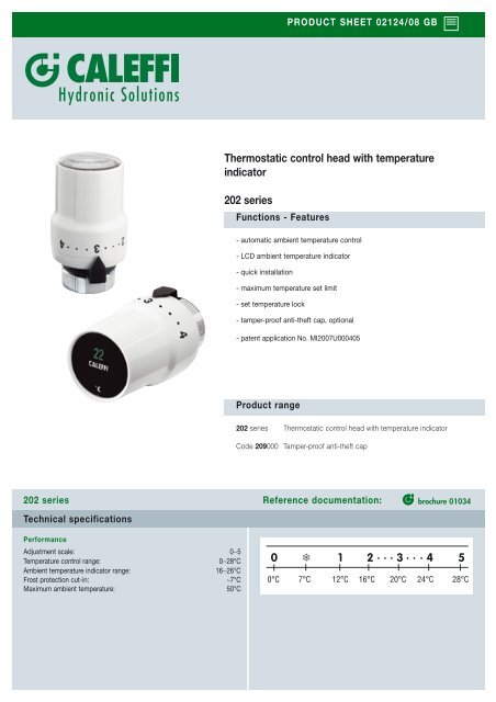
Thermostatic control head with temperature<br />
indicator<br />
202 series<br />
Functions - Features<br />
- automatic ambient temperature control<br />
- LCD ambient temperature indicator<br />
- quick installation<br />
- maximum temperature set limit<br />
- set temperature lock<br />
- tamper-proof anti-theft cap, optional<br />
- patent application No. MI2007U000405<br />
Product range<br />
PRODUCT SHEET 02124/08 GB<br />
202 series Thermostatic control head with temperature indicator<br />
Code 209000 Tamper-proof anti-theft cap<br />
202 series Reference documentation: brochure 01034<br />
0 ❄ 1 2 · · · 3 · · · 4 5<br />
0°C 7°C 12°C 16°C 20°C 24°C 28°C
Temperature reading<br />
The ambient temperature indicator,<br />
mounted on the front of the<br />
thermostatic control head, is a LCD<br />
type. It gets green coloured in<br />
correspondence with the actual<br />
ambient temperature reading, to<br />
enable precise control of the<br />
ambient temperature to the desired<br />
value.<br />
Valve conversion from manual to thermostatic<br />
Locking and limiting the temperature<br />
Temperature limiting<br />
1. Turn the knob<br />
to the fully open<br />
position (Pos.5).<br />
Using a screw-driver,<br />
unlock the ring,<br />
pressing it fully<br />
towards the valve<br />
body.<br />
Locking the temperature<br />
1. Turn the knob to<br />
the fully open<br />
position (Pos.5).<br />
Using a screwdriver,<br />
unlock the<br />
ring, pressing it<br />
fully towards the<br />
valve body.<br />
Resetting the limit and locking the temperature<br />
1. Using a<br />
screw-driver, unlock<br />
the ring, pressing it<br />
fully towards the<br />
valve body.<br />
Pivoting system<br />
A particular pivoting system keeps the<br />
indicator always in vertical position,<br />
thus allowing its optimal visualization.<br />
2. Turn the knob to<br />
the new maximum<br />
open position<br />
required (e.g. Pos.3).<br />
Turn the ring<br />
anti-clockwise up<br />
to the stop.<br />
2. Position the<br />
valve at the<br />
required<br />
temperature<br />
and turn the ring<br />
clockwise up to<br />
the stop.<br />
2. Turn the knob to<br />
the fully open<br />
position and the<br />
ring anti-clockwise,<br />
up to the stop. The<br />
RESET arrows will<br />
match up.<br />
3. Re-lock the<br />
ring. The valve<br />
will now have a<br />
temperature<br />
range restriction<br />
from 0 to the set<br />
value.<br />
3. Re-lock the<br />
ring. The valve<br />
will now be<br />
locked at the set<br />
temperature.<br />
3. Re-lock the<br />
ring. The valve<br />
will now no<br />
longer have any<br />
temperature<br />
restriction or lock.<br />
We reserve the right to make changes and improvements to the <strong>product</strong>s and related data in this publication, at any time and without prior notice.<br />
CALEFFI S.P.A. · I · 28010 FONTANETO D’AGOGNA (NO) · S.R. 229, N.25 · TEL. +39 0322 8491 R.A. · FAX +39 0322 863723<br />
· www.caleffi.com · info@caleffi.com ·<br />
© Copyright 2008 <strong>Caleffi</strong>


