HAND GEOMETRY: A New Method for Biometric Recognition
HAND GEOMETRY: A New Method for Biometric Recognition
HAND GEOMETRY: A New Method for Biometric Recognition

Create successful ePaper yourself
Turn your PDF publications into a flip-book with our unique Google optimized e-Paper software.
International Journal of Soft Computing and Engineering (IJSCE)<br />
ISSN: 2231-2307, Volume-2, Issue-6, January 2013<br />
<strong>HAND</strong> <strong>GEOMETRY</strong>: A <strong>New</strong> <strong>Method</strong> <strong>for</strong><br />
<strong>Biometric</strong> <strong>Recognition</strong><br />
Nidhi Saxena, Vipul Saxena, Neelesh Dubey, Pragya Mishra<br />
Abstract- This research method demonstrates a study about<br />
personal verification and identification using hand geometry.<br />
Hand geometry used in this research consists of the lengths and<br />
widths of fingers and the width of a palm. Users can place their<br />
hands freely without the need <strong>for</strong> pegs to fix the hand placement.<br />
In this method, six different distance functions were tested and<br />
compared. Test data obtained were from different users. Among<br />
the six different distance functions, S 1 gives the best results in<br />
both verification and identification.<br />
The advantages of a hand geometry system are that it is a<br />
relatively simple method that can use low resolution images<br />
and provides high efficiency with great users’ acceptance.<br />
[1,2]<br />
Keywords: <strong>Biometric</strong>, Hand geometry, <strong>Recognition</strong>,<br />
Identification<br />
I. INTRODUCTION<br />
The need to identify people is as old as humankind.<br />
People have used some various systems to identify an<br />
individual. Conventional identification systems are based on<br />
knowledge that people have to memorize some passwords<br />
and the systems that the people have to own some photo IDs<br />
or coded cards<br />
The important drawbacks of these methods are as<br />
follows: (i) possessions can be lost, stolen or easily<br />
duplicated; (ii) knowledge can be <strong>for</strong>gotten; and (iii) both<br />
possessions and knowledge can be shared or stolen.<br />
<strong>Biometric</strong> is gaining more attention in recent years. There<br />
are many biometric systems based on different<br />
characteristics and different parts of the human body. Each<br />
biometrics has its strengths and weakness depending on its<br />
application and use. A system that uses hand and finger<br />
geometry is one of the effective ways <strong>for</strong> identification<br />
purposes. The physical properties of a human hand contain<br />
some in<strong>for</strong>mation that is useful <strong>for</strong> authenticating the<br />
identity of an individual. Each human hand has its own<br />
characteristics and unique. Finger length, widths of the<br />
fingers, palm width, thickness or locations of fingers<br />
distinguish a human being from the others.<br />
<strong>Biometric</strong> recognition systems can eliminate these problems.<br />
<strong>Biometric</strong>s deals with identification of individuals based on<br />
their biological or behavioral characteristics. A number of<br />
biometric characteristic exist and are use in various<br />
applications including hand and finger geometry, voice,<br />
face, fingerprint, iris, gait, DNA, retinal scan, odor,<br />
keystroke, signature, and infrared facial and hand vein<br />
thermo grams.<br />
Manuscript received on January, 2013.<br />
Nidhi Saxena, Department of Computer Science, Institute of<br />
Engineering IPS Academy, Indore (M.P.), India.<br />
Vipul Saxena, Department of Mechanical, / Oriental Institute of<br />
Science and Technology, Bhopal (M.P.), India.<br />
Neelesh Dubey, Department of Computer Science, All Saint’s College<br />
of Technology, Bhopal (M.P.), India.<br />
Pragya Mishra, Department of Computer Science, Gwalior Institute of<br />
In<strong>for</strong>mation Technology, Gwalior (M.P.) India.<br />
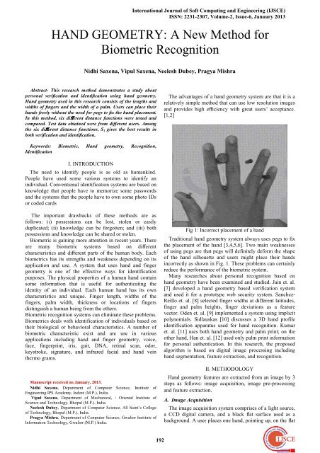
Fig 1: Incorrect placement of a hand<br />
Traditional hand geometry system always uses pegs to fix<br />
the placement of the hand [3,4,5,6]. Two main weaknesses<br />
of using pegs are that pegs will definitely de<strong>for</strong>m the shape<br />
of the hand silhouette and users might place their hands<br />
incorrectly as shown in Fig. 1. These problems can certainly<br />
reduce the per<strong>for</strong>mance of the biometric system.<br />
Many researches about personal recognition based on<br />
hand geometry have been examined and studied. Jain et. al.<br />
[7] developed a hand geometry based verification system<br />
and used it <strong>for</strong> a prototype web security system. Sanchez-<br />
Reillo et. al. [8] selected finger widths at different latitudes,<br />
finger and palm heights, finger deviations as a feature<br />
vector. Oden et. al. [9] implemented a system using implicit<br />
polynomials. Sidlauskas [10] discusses a 3D hand profile<br />
identification apparatus used <strong>for</strong> hand recognition. Kumar<br />
et. al. [11] uses both hand geometry and palm print; on the<br />
other hand, Han et. al. [12] used only palm print in<strong>for</strong>mation<br />
<strong>for</strong> personal authentication. In this research, the proposed<br />
algorithm is based on digital image processing including<br />
hand segmentation, feature extraction, and recognition.<br />
II. METHODOLOGY<br />
Hand geometry features are extracted from an image by 3<br />
steps as follows: image acquisition, image pre-processing<br />
and feature extraction.<br />
A. Image Acquisition<br />
The image acquisition system comprises of a light source,<br />
a CCD digital camera, and a black flat surface used as a<br />
background. A user places one hand, pointing up, on the flat<br />
192
<strong>HAND</strong> <strong>GEOMETRY</strong>: A <strong>New</strong> <strong>Method</strong> For <strong>Biometric</strong> <strong>Recognition</strong><br />
surface with the back of the hand touching the flat surface.<br />
The user can place a hand freely since there is no peg to fix<br />
the position of the hand. Then an image is acquired by using<br />
a CCD digital camera.<br />
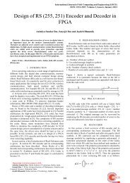
Fig.2: Example images from image preprocessing process.<br />
The reference point is simply the middle point between S1<br />
and E1. The next step is to find all the fingertips and valley<br />
points of the hand. The distances between the reference<br />
point and each contour point of the hand , from S1 to E1, are<br />
measured by Euclidean distance as defined in equation 1.<br />
D =<br />
Where (x, y) is a point in the contour and (x r , y r ) is the<br />
reference point.<br />
Comparing the distances with those of other neighbor<br />
points’ on the hand contour in some distances, the fingertips<br />
are the points that have the most distances, and the valley<br />
points, the least. The result positions of fingertips and valley<br />
points are marked as circles and shown in Fig. 4.<br />
The extracted features used in our research are the lengths<br />
of each finger, the widths of each finger at 3 locations and<br />
the width of the palm. This results in 21 features all<br />
together. These features can be found as follows.<br />
Fig.3: Example images from Image Acquisition.<br />
Users are only requested to make surethat their fingers do<br />
not touch one another and that the back of the hand lies flat<br />
and stays on the flat surface. In our experiments, only the<br />
left hand images of the users are acquired.<br />
B. Image Preprocessing<br />
Since the acquired image is a color image, it is converted<br />
to a grayscale image. Median filter is applied to remove<br />
noise in the image. Because of the black background, there<br />
is a clear distinct in intensity between the hand and tha<br />
background. There<strong>for</strong>e, the histogram of the image is<br />
bimodal. The image can be easily converted to binary image<br />
by thersholding. The threshold value is automatically<br />
computed using Otsu method [13,14]. Then the border of the<br />
hand silhouette is smoothed by using morphological opening<br />
and closing. The result is shown in fig. 2.<br />
Firstly, the reference position on a wrist, as shown in Fig.<br />
4, must be found. By scanning the pixels at the bottom of the<br />
image from left to right, the left-most pixel of the hand<br />
image, S1, and the right-most pixel, E1 are located.<br />
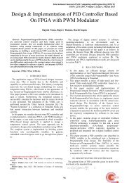
Fig.5: Fingertips and valley points of a hand.<br />
Fig.6: Definitions of finger lengths and widths.<br />
Fig.4: Example images from image preprocessing process.<br />
Fig.7: Definitions of finger baselines.<br />
193
International Journal of Soft Computing and Engineering (IJSCE)<br />
ISSN: 2231-2307, Volume-2, Issue-6, January 2013<br />
B. 1 Finger Baselines<br />
The finger baselines of a middle finger and a ring finger<br />
are obtained by connecting the valley points which are on<br />
both sides of that particular finger. However, <strong>for</strong> a thumb, an<br />
index and a little finger; each has only one adjacent valley<br />
point. Thus, in our research, the other valley points are<br />
assumed to be on the opposite side of the finger with the<br />
same distance from the fingertip to the existing valley point.<br />
For example, the located valley point of an index is on the<br />
right of the index contour with a distance D1 from the index<br />
fingertip as shown in Fig 5.<br />
There<strong>for</strong>e, the assumed other valley point of the index must<br />
be D1 distance on the left of the index contour as well. All<br />
valley points are located and shown in Fig. 5. Baselines are<br />
the lines connected between two valley points, also shown in<br />
Fig. 5 as dashed lines.<br />
Fig.8: Definitions of a palm width.<br />
B.2 Finger Lengths<br />
The “finger lengths” are obtained by measuring the<br />
distances from the fingertips to the middle points of the<br />
finger baselines. These finger lengths are shown in Fig. 6.<br />
B.3 Finger Widths<br />
In this research, the “finger widths” are the widths of a<br />
finger measured at 3 locations as shown in Fig.6. The first<br />
one is measured at the middle of the finger length, the<br />
second one, at the one-third, and the last one, at the twothird<br />
of the finger length. All the finger widths are shown in<br />
Fig. 6.<br />
B.4 Palm Width<br />
The “palm width” is the distance from b1 to b2 in<br />
database. The matching process can be divided into two<br />
types based on the application. They are verification and<br />
identification. Distance functions are utilized in the<br />
matching process to help differentiate the authorized and<br />
unauthorized persons. More details of this process are<br />
described in this section.<br />
III. PERSONAL VERIFICATION AND<br />
IDENTIFICATION<br />
A biometric system is like other authentication systems in<br />
that an authorized user has to register oneself to the system<br />
be<strong>for</strong>e verification or identification can be accomplished.<br />
The extracted bio data of the registered person is stored as a<br />
template in a database. In order to authorize an individual,<br />
the system matches the claimer’s bio data with the<br />
template(s) in the database.<br />
Fig.9: Hand geometry features<br />
The matching process can be divided into two types based<br />
on the application. They are verification and identification.<br />
Distance functions are utilized in the matching process to<br />
help differentiate the authorized and unauthorized persons.<br />
More details of this process are described in this section.<br />
B.1 Verification and Identification<br />
For a verification system, an individual claims as one of<br />
the authorized users previously registered to the system. The<br />
system confirms or denies the claimer by matching the<br />
individual’s extracted data with those of the claimed person<br />
which is stored in a database. There<strong>for</strong>e, a verification<br />
system does a one-to-one matching process. For an<br />
identification system, the claimer’s extracted data are<br />
matched with those of all registered persons. The system<br />
then establishes or recognizes the identity of the individual.<br />
Identification is there<strong>for</strong>e a one-to-many matching process.<br />
B.2 Distance Functions<br />
As mentioned earlier, a personal verification system and<br />
an identification system compare the claimer’s bio data with<br />
the templates in the database. Distance functions are used to<br />
decide whether the claimer is the claimed person or as<br />
whom the claimer is recognized. In this research, 6 distance<br />
functions are experimented as follows<br />
1. Distance Function -I<br />
D I = (1)<br />
2. Distance Function-II<br />
D II = (2)<br />
3. Distance Function-III<br />
D III = (3)<br />
4. Distance Function-IV<br />
D IV (4)<br />
where U ={u 1 ,u 2 ,u 3 ,…..,u n } is the feature vector of an<br />
unknown individual or a claimer, and D = {d 1 ,d 2 ,d 3 ,…,d n }is<br />
the database vector.<br />
Including the variances of the database vectors, two<br />
additional functions are also examined as follows:<br />
5. Distance Function-V<br />
D v = (5)<br />
6. Distance Function-VI<br />
D VI = (6)<br />
194
Where V={v 1, v 2, v 3,…….. v n }is the variance vector having<br />
the entries of the variances of each features in the database<br />
vector. To measure the similarity and find the best match, a<br />
statistical method correlation is also used. Correlation is an<br />
effective technique <strong>for</strong> image recognition. This method<br />
measures the correlation coefficient between a number of<br />
known vectors with the same size unknown vectors with the<br />
highest correlation coefficient between the vectors<br />
producing the best match. There are two <strong>for</strong>ms of<br />
correlations: autocorrelation and cross correlation. Autocorrelation<br />
function (ACF) involves only one vector and<br />
provides in<strong>for</strong>mation about the structure of the vector or the<br />
data. Cross correlation function (CCF) is a measure of the<br />
similarities or shared properties between two vectors. Since<br />
there are two vectors as unknown input feature vector and<br />
known database vector in this study, cross-correlation is<br />
used. In the simplest <strong>for</strong>m, the correlation between f (x, y)<br />
and w(x, y) is as the following:<br />
c( x,y)= f (s,t)w(x +s, y+ t) (7)<br />
IV. EXPERIMENTS AND RESULTS<br />
In our research, we divide the tests into 2 operation<br />
modes, a verification mode and an identification mode. Six<br />
different distance functions, as shown in section 3.2, are<br />
used in the feature matching process. The data used in the<br />
experiments are described in section 4.1 and the experiments<br />
and results of a verification mode and an identification mode<br />
are illustrated in sections 4.2 and 4.3 respectively.<br />
A. Data Used in Our Experiments<br />
There are 96 test users in our experiments. Ten left-hand<br />
images are acquired from each user. These images are<br />
divided into 2 groups. The first group consists of the images<br />
of all 96 users, 5 images from each user. They are used <strong>for</strong><br />
the enrolment process to define the users’ templates, or<br />
feature vectors. The features are extracted as mentioned<br />
earlier in section 2.2. Five hand images from each user are<br />
used <strong>for</strong> <strong>for</strong>ming the database feature vectors. The average<br />
values of each feature are kept as the database vectors, and<br />
also the variances of each extracted features are registered<br />
<strong>for</strong> recognition purposes. The other hand images are used <strong>for</strong><br />
testing the per<strong>for</strong>mance of the proposed algorithm. The<br />
algorithm has been tested on both identification and<br />
verification tasks.<br />
In identification, an unknown individual feature vector is<br />
matched with all the vectors registered in the database and<br />
the algorithm determines or makes a decision that the<br />
claimer is one of the registered users or not and the system<br />
identifies the claimer. The per<strong>for</strong>mance of the algorithm is<br />
evaluated by the system’s percent error or by the correct<br />
identification rate. The algorithm used six distance functions<br />
and correlation function defined on the recognition section<br />
<strong>for</strong> matching the claimer vector with the vectors on the<br />
database. The results <strong>for</strong> identification task are given in<br />
Table-1.<br />
TABLE-I<br />
Identification Per<strong>for</strong>mance Test Results<br />
Matching Algorithm<br />
Identification Rate<br />
Distance-I % 94.68<br />
Distance-II % 93.94<br />
Distance-III % 92.02<br />
Distance-IV % 94.04<br />
Distance-V % 56.64<br />
Distance-VI % 55.15<br />
Correlation % 91.71<br />
<strong>HAND</strong> <strong>GEOMETRY</strong>: A <strong>New</strong> <strong>Method</strong> For <strong>Biometric</strong> <strong>Recognition</strong><br />
Table-I shows that the matching algorithm using the<br />
Distance-IV function and the algorithm using the correlation<br />
have better correct identification rates. If these two functions<br />
can be combined with their weights, this new function can<br />
give better result. The per<strong>for</strong>mance of this matching<br />
algorithm is %97.44.<br />
B. Experiments and Results from Verification Mode<br />
In verification, the process involves matching a given<br />
hand to a person previously enrolled in the database. The<br />
claimer feature vector is then compared with the feature<br />
vector stored in the database associated with the claimed<br />
identity and the system decides that the claimer is right or<br />
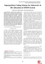
not. Verification per<strong>for</strong>mance is measured from the two<br />
types of errors; False Rejection Rate (FRR) and False<br />
Acceptance Rate (FAR). FRR is the measure of the<br />
likelihood that the system will incorrectly reject a claimer. A<br />
system’s FRR simply is stated as the ratio of the number of<br />
false rejections divided by the number of verification<br />
attempts. FAR is the measure of the likelihood that the<br />
system will incorrectly accept a claimer. FAR is stated as<br />
the ratio of the number of false acceptances divided by the<br />
number of verification attempts. The optimal per<strong>for</strong>mance of<br />
the system is obtained when the FRR equals FAR. If the<br />
threshold that the system decides according to is selected as<br />
FRR is equal to FAR, then the system’s correct verification<br />
rate is obtained. The proposed algorithm was tested with<br />
eight matching algorithms. The results are summarized in<br />
Table-2.<br />
TABLE-II<br />
Verification Per<strong>for</strong>mance Test Results<br />
Matching Algorithm Verification Error<br />
Distance-I % 97.23<br />
Distance-II % 96.06<br />
Distance-III % 95.88<br />
Distance-IV % 97.07<br />
Distance-V % 82.46<br />
Distance-VI % 71.18<br />
Correlation % 95.85<br />
Sum of weighted<br />
% 98.72<br />
Distance-VI and<br />
weighted-correlation<br />
FRR= ,<br />
f(x i )= (8)<br />
Where Fi is the feature vector of the test image of the ith<br />
user. FCi is the feature vector template of the claimed<br />
identity that, in this case, the same person as the claimer.T is<br />
a predefined threshold. f (xi) is the function that equals one<br />
when the distance is higher than the threshold. Dx (Fi, YCi )<br />
is the distance measured from matching the feature vector<br />
with the template YCi .N is the total number of test<br />
claimers’ images. In contrast with the FRR, the FAR is<br />
obtained by testing the system by matching the extracted<br />
features of a claimer with the templates of other registered<br />
persons’. In this research, the templates of other registered<br />
users’ are randomly selected <strong>for</strong> matching. Distance (Dx)<br />
from the matching process is measured and compared with a<br />
predefined threshold. In order to make the FAR and FRR<br />
comparable, the predefined thresholds used <strong>for</strong> the processes<br />
of finding FRR and FAR must be set equally. The FAR is<br />
calculated by equation (9) as follows:<br />
195
International Journal of Soft Computing and Engineering (IJSCE)<br />
ISSN: 2231-2307, Volume-2, Issue-6, January 2013<br />
FRR= ,<br />
f(x i )= (9)<br />
[12] C. C. Han, H.L. Cheng,C. L. Lin, and K C.Fan, “Personal<br />
authentication using palm printfeatures,” Pattern Recognit., Vol. 36,<br />
2003, pp. 371–381.<br />
[13] N. Otsu,“A Threshold Selection <strong>Method</strong> From Gray-scale<br />
Histogram,” IEEE Transaction Syst., Man, Cybern., Vol. 8, pp. 62-<br />
66, 1978.<br />
[14] Otsu, N., “A threshold selection method from gray-level<br />
histograms”, IEEE Transactions on Systems, Man, and Cybernetics,<br />
Vol. SMC-9<br />
(1), 1979, pp. 62–66.<br />
Fig.10: Graph FAR and FRR with vary threshold.<br />
VII. CONCLUSIONS<br />
In this study, we presented an algorithm <strong>for</strong> recognizing<br />
the individuals using their hands automatically. We<br />
proposed a new thresholding algorithm <strong>for</strong> separating the<br />
hand from the background image. It gave better result. We<br />
compared and tested eight different functions <strong>for</strong> matching<br />
algorithm. In identification and verification processes, the<br />
weighted-combination of distance-IV and correlation<br />
functions yields the best per<strong>for</strong>mance. The identification rate<br />
<strong>for</strong> this algorithm is % 97.44 and verification rate is %98.72<br />
giving the least error.<br />
REFERENCES<br />
[1] A. K. Jain, A. Ross, and S.Prabhakar,“An Introduction to <strong>Biometric</strong><br />
<strong>Recognition</strong>,” IEEE Transactions on circuits and Systems <strong>for</strong> Video<br />
Technology, Special Issue on Image- and Video-Based <strong>Biometric</strong>s,<br />
Vol. 14, No. 1, pp. 4-20, Jan. 2004.<br />
[2] John Chirillo, and Scott Blaul,Implementing <strong>Biometric</strong> Security,<br />
John Wiley & Sons, Apr. 2003.<br />
[3] R. Sanchez-Reillo, C. Sanchez-Avila, and A.Gonzalez-<br />
Marcos,“<strong>Biometric</strong> Identification Through Hand Geometry<br />
Measurements,” IEEE Transactions on Pattern Analysis and<br />
Machine Intelligence, Vol. 22, No. 10, pp. 1168-1171, 2000<br />
[4] Alexandra L.N. Wong and Pengcheng Shi,“Peg Free Hand<br />
Geometry <strong>Recognition</strong> Using Hierarchical Geometry and Shape<br />
Matching,” IAPR Workshop on Machine Vision Applications, Nara,<br />
Japan, pp. 281- 284, Dec. 2002.<br />
[5] Linda G. Shapiro, and George C. Stockman, Computer Vision,<br />
Prentice Hall, Jan. 2001.<br />
[6] Sezgin, M., Sankur, B., “Survey over image thresholding techniques<br />
and quantitative per<strong>for</strong>mance evaluation”, Journal of Electronic<br />
Imaging, 13 (1), 2004, pp.146–156.<br />
[7] A. K. Jain and N. Duta,“De<strong>for</strong>mable Matching of Hand Shapes <strong>for</strong><br />
Verfication,” IEEE International Conference on Image Processing,<br />
pp. 857- 861, Oct.1999.<br />
[8] R.Sanchez-Reillo,“Hand Geometry Pattern <strong>Recognition</strong> Through<br />
Gaussian Mixture Modeling,” 15 th , International Conference on<br />
Pattern <strong>Recognition</strong>, Vol. 2, pp. 937-940, Sep. 2000<br />
[9] C. Öden, A. Erçil, and B. Büke, “Combining implicit polynomials<br />
and geometric features <strong>for</strong> hand recognition,” Pattern Recognit.<br />
Lett.,Vol. 24, 2003, pp. 2145–2152.<br />
[10] D.P.Sidlauskas, “3D hand profile identification apparatus", US<br />
Patent No.4736203, 1988.<br />
[11] Y. A. Kumar, and A. K. Jain,“Personal verification using palmprint<br />
and hand geometry biometric”, in Proc. 4th Int. Conf. Audio<br />
Video-Based <strong>Biometric</strong> Person Authentication, Guild<strong>for</strong>d, U.K., Jun.<br />
9–11, 2003, pp.668–678.<br />
196