SVENSK STANDARD SS-EN 50397-1
SVENSK STANDARD SS-EN 50397-1
SVENSK STANDARD SS-EN 50397-1

You also want an ePaper? Increase the reach of your titles
YUMPU automatically turns print PDFs into web optimized ePapers that Google loves.
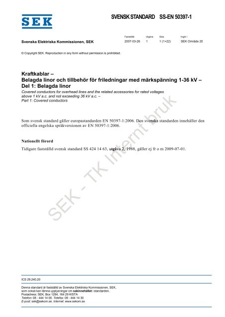
<strong>SV<strong>EN</strong>SK</strong> <strong>STANDARD</strong> <strong>SS</strong>-<strong>EN</strong> <strong>50397</strong>-1<br />
Fastställd Utgåva Sida Ingår i<br />
Svenska Elektriska Kommissionen, SEK 2007-03-26 1 1 (1+22) SEK Område 20<br />
© Copyright SEK. Reproduction in any form without permission is prohibited.<br />
Kraftkablar –<br />
Belagda linor och tillbehör för friledningar med märkspänning 1-36 kV –<br />
Del 1: Belagda linor<br />
Covered conductors for overhead lines and the related accessories for rated voltages<br />
above 1 kV a.c. and not exceeding 36 kV a.c. –<br />
Part 1: Covered conductors<br />
Som svensk standard gäller europastandarden <strong>EN</strong> <strong>50397</strong>-1:2006. Den<br />
svenska standarden innehåller den<br />
officiella engelska språkversionen av <strong>EN</strong> <strong>50397</strong>-1:2006.<br />
Nationellt förord<br />
Tidigare fastställd svensk standard <strong>SS</strong> 424 14 63, utgåva 2, 1988, gäller ej fr o m 2009-07-01.<br />
SEK - TK Internt<br />
bruk<br />
ICS 29.240.20<br />
Denna standard är fastställd av Svenska Elektriska Kommissionen, SEK,<br />
som också kan lämna upplysningar om sakinnehållet i standarden.<br />
Postadress: SEK, Box 1284, 164 29 KISTA<br />
Telefon: 08 - 444 14 00. Telefax: 08 - 444 14 30<br />
E-post: sek@sekom.se. Internet: www.sekom.se
-<br />
<br />
SEK<br />
TK<br />
<br />
<br />
<br />
<br />
<br />
Internt<br />
bruk
EUROPEAN <strong>STANDARD</strong> <strong>EN</strong> <strong>50397</strong>-1<br />
NORME EUROPÉ<strong>EN</strong>NE<br />
EUROPÄISCHE NORM November 2006<br />
ICS 29.240.20<br />
English version<br />
Covered conductors for overhead lines<br />
and the related accessories for rated voltages<br />
above 1 kV a.c. and not exceeding 36 kV a.c.<br />
Part 1: Covered conductors<br />
Conducteurs gainés pour lignes aériennes<br />
et accessoires associés pour des tensions<br />
assignées supérieures à 1 kV c.a.<br />
et ne dépassant pas 36 kV c.a.<br />
Partie 1: Conducteurs gainés<br />
Kunststoffumhüllte toffumhüllte<br />
Leiter und zugehörige<br />
Armaturen für<br />
Freileitungen mit<br />
Nennspannungen nsp<br />
nu über 1 kV und<br />
nicht mehr als 36 kV Wechselspannung<br />
Teil 1: Kunststoffumhüllte Freileitungsseile<br />
This European Standard was approved by C<strong>EN</strong>ELEC on 2006-07-01. C<strong>EN</strong>ELEC members are bound to comply<br />
with the C<strong>EN</strong>/C<strong>EN</strong>ELEC Internal Regulations which stipulate the conditions for giving this European Standard<br />
the status of a national standard d without any<br />
alteration.<br />
-<br />
Up-to-date lists and bibliographical references concerning such national standards may be obtained on<br />
application to the Central Secretariat etar<br />
or to any C<strong>EN</strong>ELEC member.<br />
This European Standard exists s in three official versions (English, French, German). A version in any other<br />
language made by translation<br />
under the responsibility of a C<strong>EN</strong>ELEC member into its own language and notified<br />
to the Central Secretariat<br />
has the same status as the official versions.<br />
C<strong>EN</strong>ELEC EC members<br />
are the national electrotechnical committees of Austria, Belgium, Cyprus, the Czech<br />
Republic, Denmark, Estonia, Finland, France, Germany, Greece, Hungary, Iceland, Ireland, Italy, Latvia,<br />
Lithuania, a, Luxembourg, Malta, the Netherlands, Norway, Poland, Portugal, Romania, Slovakia, Slovenia, Spain,<br />
Sweden, Switzerland and the United Kingdom.<br />
SEK<br />
TK<br />
Internt<br />
bruk<br />
C<strong>EN</strong>ELEC<br />
European Committee for Electrotechnical Standardization<br />
Comité Européen de Normalisation Electrotechnique<br />
Europäisches Komitee für Elektrotechnische Normung<br />
Central Secretariat: rue de Stassart 35, B - 1050 Brussels<br />
© 2006 C<strong>EN</strong>ELEC - All rights of exploitation in any form and by any means reserved worldwide for C<strong>EN</strong>ELEC members.<br />
Ref. No. <strong>EN</strong> <strong>50397</strong>-1:2006 E
<strong>EN</strong> <strong>50397</strong>-1:2006 – 2 –<br />
Foreword<br />
This European Standard was prepared by TF “Covered Overhead Line Conductors (COHL)” of the<br />
Technical Committee C<strong>EN</strong>ELEC TC 20, Electric cables.<br />
The text of the draft was submitted to the formal vote and was approved by C<strong>EN</strong>ELEC as <strong>EN</strong> <strong>50397</strong>-1 on<br />
2006-07-01.<br />
The following dates were fixed:<br />
- latest date by which the <strong>EN</strong> has to be implemented<br />
at national level by publication of an identical<br />
national standard or by endorsement (dop) 2007-07-01<br />
- latest date by which the national standards conflicting<br />
with the <strong>EN</strong> have to be withdrawn (dow) 2009-07-0109-07-01<br />
This European Standard consists of two parts:<br />
– Part 1 "Covered conductors"; and<br />
– Part 2 "Accessories for covered conductors: Tests and acceptance criteria".<br />
This standard covers the construction, performance and test requirements for covered conductors for<br />
overhead lines having a nominal voltage U above 1 kV a.c. up<br />
to<br />
and including 36 kV a.c., and for the<br />
related accessories.<br />
__________<br />
SEK - TK Internt<br />
bruk
– 3 – <strong>EN</strong> <strong>50397</strong>-1:2006<br />
Contents<br />
Introduction.............................................................................................................................................4<br />
1 Scope ...............................................................................................................................................5<br />
2 Normative references .....................................................................................................................5<br />
3 Definitions .......................................................................................................................................5<br />
4 Covered conductors.......................................................................................................................6<br />
4.1 Code designation ......................................................................................................................6<br />
4.2 Construction requirements........................................................................................................6<br />
4.2.1 Conductor ..................................................................................................................6<br />
4.2.2 Filling..........................................................................................................................7<br />
4.2.3 Covering ....................................................................................................................7<br />
5 Marking ............................................................................................................................................9<br />
5.1 Indication of origin .....................................................................................................................9<br />
5.2 Continuity of marks ...................................................................................................................9<br />
5.3 Other markings..........................................................................................................................9<br />
5.4 Durability ...................................................................................................................................9<br />
5.5 Legibility ....................................................................................................................................9<br />
6 Tests.................................................................................................................................................9<br />
Annex A (normative) Special conductors ..........................................................................................12<br />
Annex B (normative) Measurement of the leakage current..............................................................13<br />
Annex C (normative) Tracking resistance..........................................................................................15<br />
Annex D (normative) Slippage test .....................................................................................................21<br />
SEK - TK Internt<br />
bruk
<strong>EN</strong> <strong>50397</strong>-1:2006 – 4 –<br />
Introduction<br />
Covered conductors consist of a conductor surrounded by a covering made of insulating material as<br />
protection against accidental contacts with other covered conductors and with grounded parts such as<br />
tree branches, etc. In comparison with insulated conductors, this covering has reduced properties, but is<br />
able to withstand the phase-to-earth voltage temporarily.<br />
Since covered conductors are unscreened, they are not touch-proof, i.e. they must be treated as bare<br />
conductors with respect to electric shock.<br />
This standard does not cover aspects related to the installation of overhead lines such as determination<br />
of clearances, spans, sags, etc.<br />
SEK - TK Internt bruk
– 5 – <strong>EN</strong> <strong>50397</strong>-1:2006<br />
1 Scope<br />
This Part 1 contains the requirements for covered conductors with or without integrated longitudinal<br />
watertightness and/or semi-conductive conductor screen for applications in overhead lines with rated<br />
voltages U above 1 kV a.c. and not exceeding 36 kV a.c.<br />
2 Normative references<br />
The following referenced documents are indispensable for the application of this document. For dated<br />
references, only the edition cited applies. For undated references, the latest edition of the referenced<br />
document (including any amendments) applies.<br />
<strong>EN</strong> 50182<br />
<strong>EN</strong> 50356<br />
<strong>EN</strong> 60811 series<br />
Conductors for overhead lines – Round wire concentric lay stranded<br />
conductors<br />
Method for spark testing of cables<br />
Insulating and sheathing materials of electric and optical fibre<br />
cables – Common<br />
test methods (IEC 60811 series)<br />
<strong>EN</strong> 61284 Overhead lines – Requirements and tests for fittings<br />
(IEC 61284)<br />
HD 380<br />
HD 605<br />
3 Definitions<br />
Test methods for evaluating resistance to tracking and erosion of electrical<br />
insulating materials used under severe ambient conditions (IEC 60587)<br />
Electric cables – Additional test methods<br />
For the purpose of this European Standard, the following definitions apply.<br />
-<br />
3.1 Definitions relating to tests<br />
3.1.1<br />
type tests (symbol T)<br />
tests required to be made before supplying a type of product covered by this European Standard on a<br />
general commercial mercial basis in order to demonstrate satisfactory performance characteristics to meet the<br />
intended application. plication. These tests are of such nature that, after they have been made, they need not be<br />
repeated unless changes are made in the material, design or manufacturing process which might change<br />
the performance ech<br />
characteristics<br />
SEK<br />
TK<br />
Internt<br />
3.1.2<br />
sample tests (symbol S)<br />
tests made on samples of completed product or components taken from the completed product adequate<br />
to verify that the finished product meets the design specifications<br />
3.1.3<br />
routine tests (symbol R)<br />
tests made on all production lengths to demonstrate their integrity<br />
bruk<br />
3.2<br />
rated voltage<br />
the reference voltage for which the conductor is designed and which serves to define the electrical tests.<br />
The rated voltage is expressed by the value U, expressed in kilovolts, where U is the r.m.s. value<br />
between any two-phase conductors
<strong>EN</strong> <strong>50397</strong>-1:2006 – 6 –<br />
4 Covered conductors<br />
4.1 Code designation<br />
Covered conductors shall be designated as follows:<br />
Type code<br />
Covering material<br />
CC;<br />
S (for semi-conductive conductor screen, if any),<br />
X (for cross-linked polyethylene),<br />
T (for thermoplastic polyethylene);<br />
Conductor material and cross-section according to <strong>EN</strong> 50182;<br />
Conductor design<br />
Rated voltage U in kV<br />
EXAMPLE OF DESIGNATION<br />
W (for watertight),<br />
K (for compacted);<br />
…kV.<br />
“CCX 66-AL3 WK 20kV” is a XLPE-covered conductor ctor with a<br />
rated voltage of 20 kV, longitudinal<br />
watertight compacted conductor of aluminium alloy AL3 and<br />
a<br />
nominal conductor cross-section of<br />
66 mm².<br />
4.2 Construction requirements<br />
4.2.1 Conductor<br />
Number of conductors: 1<br />
Conductor material:<br />
Nom. cross-section:<br />
Conductor design:<br />
-<br />
SEK<br />
TK<br />
aluminium alloy or steel reinforced aluminium<br />
35<br />
mm² m to 240 mm² (aluminium alloy), 50 mm² to 150 mm²<br />
(total cross-section for steel reinforced aluminium)<br />
the conductors may be compacted or non-compacted.<br />
Information on bare conductors in frequent use may be found in the national lists, contained in Annex F of<br />
<strong>EN</strong> 50182. However, for the purpose of this European Standard, conductors may be selected from any<br />
national table. Conductors deviating in design from the standard values have to be given by the<br />
manufacturer, but fulfilling all requirements given in <strong>EN</strong> 50182.<br />
Non-compacted conductors shall comply with <strong>EN</strong> 50182 (with the exception of the filling, if any).<br />
For compacted conductors, based on conductors according to <strong>EN</strong> 50182, the following paragraph<br />
applies: The outer diameter of the compacted conductor shall be 95 % (± 1 % for 7- and 19-wire<br />
constructions, ± 1,5 % for 37-wire constructions) of the diameter given in <strong>EN</strong> 50182. The rated tensile<br />
strength (RTS) shall be at least 95 % of the value given in <strong>EN</strong> 50182. The d.c. resistance shall not exceed<br />
the value given in <strong>EN</strong> 50182 by more than 5 %.<br />
Special conductors may also be used (see Annex A).<br />
Internt<br />
bruk
– 7 – <strong>EN</strong> <strong>50397</strong>-1:2006<br />
4.2.2 Filling<br />
The stranded conductor may be longitudinally watertight by means of adequate measures as e.g. filling<br />
with an adequate mass. The filling mass or other materials for obtaining the longitudinal watertightness,<br />
shall be compatible with the conductor material and the material of the covering (see Table 2).<br />
4.2.3 Covering<br />
The covering shall consist of a cross-linked polyethylene compound, which shall comply with the<br />
requirements according to Table 1, column 3 or of a thermoplastic polyethylene compound, complying<br />
with the requirements according Table 1, column 4.<br />
It shall be possible to remove the covering without damage to the conductor.<br />
Table 1 – Properties of the covering materials<br />
1 2 3 4<br />
Compound designation X T<br />
Basic material XLPE PE<br />
Maximum operating temperature of the conductor °C 90 a 70<br />
Mechanical properties<br />
before ageing on sample (<strong>EN</strong> 60811-1-1, Subclause 9.1) nt90<br />
minimum tensile strength MPa<br />
12,5 12,5<br />
minimum elongation at break %<br />
200 300<br />
after ageing on sample (<strong>EN</strong> 60811-1-2, Subclause 8.1,<br />
ageing method a))<br />
temperature °C 135 110<br />
duration h 168 336<br />
minimum tensile strength MPa - 12,5<br />
maximum variation T1/T0 % ± 25 -<br />
minimum elongation at break % - 300<br />
maximum variation T1/T0 % ± 25 -<br />
after ageing on complete e product sample b<br />
(<strong>EN</strong> 60811-1-2, Subclause use 8.1.4)<br />
temperature °C 100 ± 2 100 ± 2<br />
duration h 168 168<br />
minimum tensile strength<br />
MPa - 12,5<br />
SEK K<br />
maximum variation T2/T0<br />
% ± 25 -<br />
minimum elongation at break % - 300<br />
maximum variation T2/T0 % ± 25 -<br />
Unit<br />
X<br />
br<br />
- TK Internt<br />
bruk
<strong>EN</strong> <strong>50397</strong>-1:2006 – 8 –<br />
Physical and chemical properties<br />
hot set test (<strong>EN</strong> 60811-2-1, Clause 9)<br />
Table 1 – Properties of the covering materials (continued)<br />
1 2 3 4<br />
temperature °C 200 -<br />
duration min 15 -<br />
mechanical stress MPa 0,2 -<br />
maximum elongation under load % 175 -<br />
maximum residual elongation % 15 -<br />
pressure test at high temperature (<strong>EN</strong> 60811-3-1,<br />
Subclause 8.1)<br />
temperature °C - 80<br />
duration h - 4<br />
coefficient k - - 0,8<br />
maximum depth of indentation % -<br />
50<br />
water absorption (<strong>EN</strong> 60811-1-3, Subclause 9.2)<br />
temperature °C 85 85<br />
duration h 336 336<br />
er<br />
maximum variation of mass mg/cm² m²<br />
1 1<br />
shrinkage test (<strong>EN</strong> 60811-1-3, Clause 10)<br />
distance L between marks mm 200 200<br />
duration h<br />
1 1<br />
temperature 130 ± 3 100 ± 3<br />
maximum shrinkage % 4 4<br />
Shore D hardness (HD 605, Subclause 2.2.1)<br />
In°C<br />
minimum hardness ShD - 55<br />
a<br />
Maximum operating temperature of the conductor<br />
is limited to 80 °C due to mechanical reasons.<br />
b<br />
For use together with watertight conductors only. Adequate measures e.g. neutral capping to prevent leakage of filling<br />
material shall be taken.<br />
An UV-protection shall be provided. If carbon black is used, the content of carbon black shall be<br />
(2,5 ± 0,5) %.<br />
The nominal thickness of<br />
the covering shall be calculated according to the following formula:<br />
where<br />
S = 0,111 U<br />
K<br />
Unit<br />
Internt33<br />
- TK<br />
orsTK In<br />
er<br />
rn bruk<br />
uk<br />
S<br />
U<br />
is the nominal thickness of the covering in mm (rounded to one decimal place);<br />
is the rated voltage (see 3.2) in kV.<br />
The nominal thickness of the covering shall be not less than 2,3 mm.<br />
The minimum thickness of the covering at any place shall not be less than the nominal value by more<br />
than (0,1 mm + 10 % of the nominal value). The mean value of the thickness of the covering shall not<br />
exceed the nominal value by more than (0,1 mm + 10 % of the nominal value).<br />
A semi-conductive conductor screen, if any, shall not be measured as covering thickness.
– 9 – <strong>EN</strong> <strong>50397</strong>-1:2006<br />
5 Marking<br />
5.1 Indication of origin<br />
Covered conductors shall be provided with an identification of origin consisting of a continuous marking of<br />
the manufacturer’s name or trademark on the surface of the covering. This marking shall be made by<br />
embossing.<br />
5.2 Continuity of marks<br />
The distance between the end of a mark and the beginning of the next identical mark shall not exceed<br />
1 000 mm.<br />
The diagram below shows an example of the marking, where the word "ORIGIN" stands for the<br />
mandatory information required in 5.1 and "XYZ" stands for one of any other mandatory marks required in<br />
5.3.<br />
5.3 Other markings<br />
ORIGIN<br />
XYZ<br />
ORIGIN<br />
Covered conductors shall be equipped with a<br />
continuous embossing as follows:<br />
– code designation according to 4.1;<br />
– year of production;<br />
– standard number.<br />
XYZ<br />
Optional markings (e.g. slippage factor according to Annex D, meter marking) may be added upon<br />
agreement between en manufacturer and user. These optional markings may be made by printing or<br />
embossing.<br />
5.4 Durability<br />
Printed markings shall be durable. Durability shall be checked by the test according to HD 605,<br />
Subclause 2.5.4. The markings shall be legible after this test.<br />
5.5 Legibility<br />
SEK<br />
- TK<br />
br<br />
b<br />
Internt<br />
bruk<br />
All markings shall be clearly legible. Printed markings shall be in contrasting colours.<br />
6 Tests<br />
The compliance with the requirements according to 4.2 and Clause 5 shall be established by visual<br />
examination and the tests listed in Table 2.<br />
A type test shall be performed on every covered conductor type, irrespective of the cross sectional area.<br />
The results will be valid across the whole range of cross sectional areas for that type.
<strong>EN</strong> <strong>50397</strong>-1:2006 – 10 –<br />
NOTE The slippage test shall be performed on each cross sectional area (see D.3.1).<br />
Table 2 – Tests<br />
1 2 3 4 5<br />
No Tests Category<br />
of tests<br />
1 Electrical tests<br />
Requirements<br />
1.1 Conductor resistance T,<br />
S b<br />
1.2 High voltage test<br />
1.2.1 – for CC without conductor screen: no breakdown<br />
1.2.2<br />
Test voltage (a.c.)<br />
Number of specimen 1<br />
Length of specimen (minimum)<br />
Duration of immersion in water (minimum)<br />
1 U<br />
5 m<br />
1 h<br />
Temperature of water (20 ± 5) °C<br />
Test duration<br />
15 min<br />
3 h<br />
– for CC with conductor screen or upon agreement between<br />
customer and producer:<br />
Test voltage (a.c.)<br />
Number of specimen 1<br />
Length of specimen (minimum)<br />
1 U<br />
5 m<br />
Duration of immersion in water (minimum)<br />
1 h<br />
Temperature of water (20 ± 5) °C<br />
Test duration<br />
4 h<br />
48 h<br />
S<br />
T<br />
S<br />
T<br />
a<br />
no breakdown<br />
Test methods<br />
HD 605,<br />
Subclause 3.1.1<br />
HD 605,<br />
Subclause 3.2.2.2<br />
HD 605,<br />
Subclause 3.2.2.2<br />
1.3 Spark test on the covering c R no breakdown <strong>EN</strong> 50356<br />
Test voltage:<br />
a.c. 0,7 U or<br />
d.c. 1 U<br />
1.4 Leakage current T maximum 1 mA Annex B<br />
Test voltage<br />
(a.c.)<br />
0,7 U<br />
1.5 Tracking resistance d<br />
T Annex C Annex C<br />
2 Construction and dimensions<br />
2.1 Compliance with the design requirements T, S, R Subclause 4.2 visual inspection<br />
2.2 Thickness of the covering T, S, R Subclause 4.2.3 <strong>EN</strong> 60811-1-1,<br />
Subclause 8.1<br />
3 Construction and mechanical properties of the conductor<br />
3.1 Rated tensile strength T, S b a a<br />
3.2 Construction and dimensions T, S<br />
a<br />
a<br />
4 Non-electrical tests on the covering<br />
4.1 Mechanical properties<br />
a) before ageing of sample T Subclause 4.2.3 <strong>EN</strong> 60811-1-1,<br />
Subclause 9.1<br />
b) after ageing of sample T Subclause 4.2.3 <strong>EN</strong> 60811-1-2,<br />
Subclause 8.1,<br />
ageing method a)<br />
SEK<br />
- TK Internt<br />
t<br />
bruk
– 11 – <strong>EN</strong> <strong>50397</strong>-1:2006<br />
Table 2 – Tests (continued)<br />
1 2 3 4 5<br />
No Tests Category<br />
of tests<br />
Requirements<br />
Test methods<br />
4.2 Carbon black content e T Subclause 4.2.3 <strong>EN</strong> 60811-4-1,<br />
Clause 11<br />
4.3 Resistance to UV rays f T HD 605 S1:1994<br />
/A2 :2001,<br />
Subclause 2.4.23<br />
5 Test of compatibility g<br />
Ageing of complete product sample T Subclause 4.2.3 <strong>EN</strong> 60811-1-2,<br />
Subclause 8.1.4<br />
6 Thermal properties of the covering<br />
6.1 Shrinkage test T Subclause 4.2.3 <strong>EN</strong> 60811-1-3,<br />
Clause 10<br />
Distance “L” between marks<br />
(200 ± 5) mm<br />
kE<br />
kCla<br />
6.2 Hot-set-test h T, S Subclause 4.2.3 <strong>EN</strong> 60811-2-1,<br />
Clause 9<br />
6.3 Pressure test at high temperature i T Subclause 4.2.3 <strong>EN</strong> 60811-3-1,<br />
Subclause 8.1<br />
7 Further tests on the covering<br />
7.1 Water absorption T Subclause 4.2.3 <strong>EN</strong> 60811-1-3,<br />
Subclause 9.2<br />
7.2 Shore D hardness i T Subclause 4.2.3 HD 605,<br />
Subclause 2.2.1<br />
8 Test of the longitudinal watertightness g<br />
8.1<br />
8.2<br />
With heat cycle T no leakage<br />
Number of specimen 1<br />
Length of specimen<br />
Test duration<br />
Bending radius<br />
3 m<br />
24 h<br />
20 D<br />
Without heat cycle S no leakage<br />
Number of specimen 1<br />
Length of specimen<br />
Test duration<br />
1 m<br />
1 h<br />
IEC 60502-2,<br />
Annex F<br />
IEC 60502-2,<br />
Annex F j<br />
9 Marking<br />
9.1 Content, legibility<br />
T, S, R Clause 5 visual inspection<br />
9.2 Durability T Subclause 5.4 HD 605,<br />
Subclause 2.5.4<br />
10 Slippage test T Annex D Annex D<br />
a<br />
Requirements and/or test procedures respectively, whatever applicable, according to <strong>EN</strong> 50182, to Annex A of this<br />
standard or to 4.2.1 of this standard.<br />
b<br />
For compacted conductors only<br />
c<br />
Alternatively a high voltage test can be performed on the whole production length under the following conditions: Test<br />
voltage 4 kV a.c., duration of immersion in water (minimum) 10 minutes, water temperature (20 ± 5) °C, test duration 5<br />
minutes, no break down.<br />
d<br />
For U ≥ 30 kV or on request<br />
e<br />
f<br />
g<br />
h<br />
i<br />
j<br />
etS EK<br />
If carbon black is used for UV-stabilisation<br />
If other than carbon black is used for UV-stabilisation<br />
For longitudinal watertight versions only.<br />
For cross-linked polyethylene only<br />
For thermoplastic polyethylene only<br />
- TK Internt<br />
Tr t<br />
Water column connected to one end of specimen by means of an appropriate fitting.<br />
bruk
<strong>EN</strong> <strong>50397</strong>-1:2006 – 12 –<br />
Annex A<br />
(normative)<br />
Special conductors<br />
In addition to the conductors described in 4.2.1, the conductors in Table A.1 may be used.<br />
These conductors shall be compacted. All wires shall be stranded together according to <strong>EN</strong> 50182,<br />
Subclauses 5.5 and 5.6.<br />
Table A.1 – Special conductors<br />
uk<br />
1 2 3 4 5 6<br />
Code<br />
Minimum<br />
Nominal Rated tensile Mass s per unit<br />
Maximum d.c.<br />
number of conductor<br />
strength<br />
length<br />
resistance at +20 °C<br />
wires<br />
diameter<br />
mm kN Ω/km<br />
35-AL2 7 6,9 ± 0,20 10,3 91 0,986<br />
bkg/km<br />
50-AL2A 7 8,0 ± 0,20 14,2 123 0,720<br />
50-AL2B 7 8,3 - 0,2/+ 0,4 14,7<br />
nt1 135 0,720<br />
70-AL2 7 9,7 ± 0,25 20,6 182 0,493<br />
95-AL2A 7 11,3 ± 0,30 27,9<br />
249 0,363<br />
95-AL2B 7 11,6 - 0,2/+ 0,4 26,9<br />
256 0,363<br />
120-AL2 19 12,8 ± 0,30 35,2<br />
315 0,288<br />
150-AL2 19 14,2 ± 0,30 43,4<br />
390 0,236<br />
150-AL7 19 14,2 - 0,2/+<br />
0,4 30,4 405 0,198<br />
185-AL2 34 15,8 ± 0,30<br />
54,3 487 0,188<br />
240-AL2 34 18,1 ± 0,35<br />
70,4 638 0,145<br />
SEK - TK Internt<br />
nt bruk<br />
uk
– 13 – <strong>EN</strong> <strong>50397</strong>-1:2006<br />
Annex B<br />
(normative)<br />
Measurement of the leakage current<br />
B.1 Test equipment<br />
− a.c.-source with power frequency (48 Hz to 62 Hz), an output voltage of 0,7 U and an output current of<br />
5 mA at least<br />
− Ampere meter (true r.m.s.) with an accuracy of ± 0,1 mA at least<br />
− Resistor (1 ± 0,05) kΩ<br />
− Plain copper wire with a diameter of (2,0 ± 0,05) mm<br />
− Ethanol<br />
− Water tank<br />
B.2 Sampling<br />
The specimen shall be taken at least 5 m away from any end of a production length. The length of the<br />
specimen shall be (1 000 ± 10) mm.<br />
The surface of the covering of the specimen shall be cleaned<br />
from any present contamination by wiping<br />
off with ethanol. Then the specimen shall be immersed mersed in water at a temperature of (20 ± 5) °C for 24 h at<br />
least. The further preparations and the test shall be performed immediately after the end of the immersion<br />
in water. The specimen shall be dried by wiping it off to<br />
ensure, that no moisture connections between the<br />
measuring electrode and the conductor can occur.<br />
On one end of the specimen, the covering<br />
shall be removed over a length of (5 ± 1) mm and the<br />
conductor surface shall be cleaned.<br />
TK<br />
At a distance of (450 ± 5) mm from the other end of the specimen, a plain copper wire with a diameter of<br />
(2,0 ± 0,05) mm shall be<br />
wound around the covering to build up a closed helix with a length of<br />
(100 ± 2) mm (measured in the<br />
axis of the specimen) as a measuring electrode. The winding of the<br />
copper wire shall be done in<br />
a way which avoids any damage and minimizes deformation of the covering.<br />
-om<br />
SEK<br />
(450 ± 5) mm<br />
(1 000 + 10) mm<br />
Internt<br />
(100 ± 2) mm (5 ± 1) mm<br />
bruk<br />
A<br />
(1 ± 5 %) kΩ<br />
0,7 U AC<br />
Figure B.1 – Test arrangement
<strong>EN</strong> <strong>50397</strong>-1:2006 – 14 –<br />
B.3 Test procedure<br />
Between the conductor and the measuring electrode the voltage shall be applied and the current shall be<br />
measured by the ampere meter. The value of the current shall be read one minute after application of the<br />
voltage.<br />
B.4 Test evaluation<br />
The measured value of the current shall not exceed the value given in Table 2.<br />
SEK - TK Internt bruk
– 15 – <strong>EN</strong> <strong>50397</strong>-1:2006<br />
Annex C<br />
(normative)<br />
Tracking resistance<br />
C.1 Scope and object<br />
This annex, based on HD 380 (IEC 60587), describes the test method for the evaluation of electrical<br />
insulating materials for use at power frequencies (48 Hz to 62 Hz) by measurement of the resistance to<br />
tracking and erosion, using a liquid contaminant and inclined cable samples.<br />
NOTE 1 The test conditions are designed to accelerate the production of the effects, but do not reproduce r all the conditions<br />
encountered in service.<br />
With the test apparatus described in the following sub-clauses, the track starts at the lower electrode.<br />
The end point of the test is reached when the value of the current in the high voltage circuit through the<br />
specimen exceeds 60 mA. An overcurrent device then breaks this circuit.<br />
it.<br />
NOTE 2 This end point criterion permits the use of an automatic apparatus testing several<br />
specimens simultaneously.<br />
C.2 Definitions<br />
C.2.1<br />
track<br />
conducting or partially conducting path created by tracking<br />
TK<br />
C.2.2<br />
tracking<br />
progressive degradation of the surface of<br />
a solid insulation material by local discharges to form<br />
conducting or partially conducting paths<br />
C.2.3<br />
erosion, electrical<br />
wearing away of electrical cal insulating ing material by the action of electrical discharges<br />
C.2.4<br />
time-to-track<br />
time in a tracking test until tracking reaches a specified end-point criterion<br />
C.3 Test specimens<br />
C.3.1 Dimensions<br />
Specimens of finished covered conductor at least 200 mm in length.<br />
C.3.2 Preparation<br />
-<br />
Internt<br />
bruk<br />
Unless otherwise specified, the surface of the specimens shall be lightly abraded. The abrasion should be<br />
done with a fine silicon carbide abrasive paper Number 600 under de-ionized or distilled water until the<br />
whole surface wets and appears uniformly matted when dry. If abrasion has not been used, the method of<br />
cleaning shall be mentioned in the test report.
<strong>EN</strong> <strong>50397</strong>-1:2006 – 16 –<br />
C.4 Apparatus<br />
C.4.1 Electrical apparatus<br />
A schematic circuit is given in Figure C.1. As the test will be carried out at high voltages, it is obviously<br />
necessary to use a grounded safety enclosure.<br />
Key<br />
S power supply switch<br />
VT variable ratio transformer<br />
T high-voltage transformer<br />
R series resistor<br />
V voltmeter<br />
Sp specimen<br />
F overcurrent device, fuse or relay<br />
The circuit comprises:<br />
C.4.1.1 Power supply<br />
-<br />
Figure C.1 – Schematic circuit diagram<br />
A power supply with an output voltage stabilized to ± 5 % with a rated current not less than 0,1 A for each<br />
specimen. The test voltage shall be<br />
according to Table C.1, column 1.<br />
NOTE If only one power supply is used for several specimens, each should have a circuit-breaker or similar device (see C.4.1.4).<br />
C.4.1.2 Resistor<br />
A 200 W resistor with ±<br />
10 % resistance tolerance shall be connected in series with each specimen on<br />
the high-voltage ge side<br />
of the power supply. The resistance of the resistor shall be taken from Table C.1,<br />
column 3.<br />
SEK<br />
TK<br />
Internt<br />
bruk<br />
Table C.1 – Series resistor and contaminant flow rate<br />
1 2 3<br />
Test voltage<br />
Contaminant<br />
Flow rate<br />
Series resistor,<br />
Resistance<br />
kV ml/min kΩ<br />
3,5 0,30 22<br />
C.4.1.3<br />
Voltmeter<br />
A voltmeter with an accuracy of 1,5 % of reading.
– 17 – <strong>EN</strong> <strong>50397</strong>-1:2006<br />
C.4.1.4<br />
Overcurrent delay relay<br />
An overcurrent delay relay (for example see Figure C.2) or any other device which operates when 60 mA<br />
or more has persisted in the high-voltage circuit for 2 s.<br />
Key<br />
Re rectifier<br />
Tr transformer (winding 300/900 turns)<br />
Rl relay (2 500 Ω / 11 000 turns)<br />
C capacitor (200 μF)<br />
C.4.2 Electrodes<br />
To the power supply switch<br />
(S in Figure C.1)<br />
Figure C.2 – Typical circuit cuit for<br />
an overcurrent delay relay<br />
All electrodes, fixtures and assembly elements associated with the electrodes, such as screws, shall be<br />
made of stainless steel. The electrode assembly is shown in Figure C.3 . The electrodes shall be cleaned<br />
prior to each test and replaced when<br />
necessary.<br />
-<br />
SEK<br />
TK<br />
Internt<br />
bruk
<strong>EN</strong> <strong>50397</strong>-1:2006 – 18 –<br />
Figure C.3 – Test assembly sembly schematic<br />
C.4.2.1 Top electrode<br />
All dimensions in mm<br />
The top electrode is shown in Figure C.4. .<br />
This electrode is fixed to the sample with a suitable plastic<br />
cable tie passed through the oval holes and around dth<br />
the sample.<br />
TK Internt bruk<br />
All dimensions in mm<br />
Figure C.4 – Top electrode, stainless steel, 0,5 mm thick<br />
C.4.2.2<br />
Bottom electrode<br />
The bottom electrode is a standard stainless steel screw clamp.
– 19 – <strong>EN</strong> <strong>50397</strong>-1:2006<br />
C.4.3 Contamination<br />
C.4.3.1<br />
Contaminant<br />
Unless otherwise specified use:<br />
(0,1 ± 0,002) % by mass of NH 4 CI (ammonium chloride) analytical quality and (0,02 ± 0,002) % by mass<br />
of iso-octylphenoxypolyethoxyethanol (a non-ionic wetting agent) in distilled or de-ionized water.<br />
This contaminant shall have a resistivity of (3,95 ± 0,05) Ω.m at (23 ± 1) °C.<br />
The contaminant shall be not more than four weeks old and its resistivity shall be checked before each<br />
series of tests.<br />
C.4.3.2<br />
Applicator paper<br />
Eight layers of filter-paper of the approximate dimensions in mm given in Figure<br />
C.5 are clamped<br />
between the top electrode and the specimen to act as a reservoir for the contaminant.<br />
C.4.3.3<br />
Contaminant nant flow<br />
Figure C.5 – Applicator paper<br />
All dimensions in mm<br />
The contaminant nant shall be fed into this filter-paper pad so that a uniform flow between the top and the<br />
bottom electrodes shall occur before voltage application.<br />
SEK<br />
- TK nt bruk<br />
NOTE This can be done by pumping the contaminant through a tube into the filter paper pad. The tube can be held between the<br />
filter papers by a clip of stainless steel. Another possibility is to drip the contaminant into the filter paper pad with a fixed drop size<br />
and fixed number of drops per minute.<br />
C.4.3.4<br />
Flow rate<br />
The rate of application of contaminant shall be that specified in Table C.1, column 2.<br />
C.4.4 Timing device<br />
A timing device with an accuracy better than ± 1 min/h.<br />
NOTE For example a 1 min pulser with a counter is acceptable.
<strong>EN</strong> <strong>50397</strong>-1:2006 – 20 –<br />
C.4.5 Depth gauge<br />
A depth gauge with an accuracy of ± 0,01 mm. The point of the probe shall be hemispherical with a radius<br />
of 0,25 mm.<br />
C.5 Procedure<br />
C.5.1 Preparation of the test<br />
C.5.1.1<br />
Ambient conditions<br />
Unless otherwise specified, the test shall be carried out at an ambient temperature of (23 ± 2) °C on five<br />
specimens.<br />
C.5.1.2<br />
Mounting<br />
The specimen shall be mounted at an angle of 45° to the horizontal as shown in Figure C.3 with the<br />
electrodes (50 ± 0,5) mm apart.<br />
For each test, a new filter-paper pad shall be used.<br />
C.5.1.3<br />
Adjustment of the contaminant flow<br />
Start introducing the contaminant into the filter-paper r pad allowing the contaminant to wet the paper<br />
thoroughly. Adjust the contaminant flow and calibrate to give<br />
a flow rate as specified in Table C.1,<br />
column 2. Observe the flow for at least 10 min and ensure that the contaminant flows steadily down the<br />
face of the test specimen between the electrodes. es. The contaminant shall flow from the quill hole of the top<br />
electrode and not from the sides or the top of the filter-paper.<br />
C.5.2 Application of the voltage<br />
TK<br />
With the contaminant flowing uniformly at the<br />
specified rate, according to Table C.1, column 2, switch on<br />
and raise the voltage to the test level according to Table C.1, column 1 and start the timing device. The<br />
voltage shall be maintained constant for 6 h.<br />
C.5.3 Test evaluation ation<br />
The test is successful cessful if the<br />
current in the high-voltage circuit does not exceed 60 mA for any of the five<br />
specimens during 6 h.<br />
The maximum depth<br />
of erosion shall be reported.<br />
C.6 Test report<br />
The report shall include:<br />
-<br />
SEK<br />
Internt<br />
bruk<br />
Type and designation of the specimen tested.<br />
Details of the specimens: Dimensions, cleaning procedure and solvent used, surface treatment if any.<br />
The covering thickness shall be reported.
– 21 – <strong>EN</strong> <strong>50397</strong>-1:2006<br />
Annex D<br />
(normative)<br />
Slippage test<br />
D.1 Scope and object<br />
This annex describes the test method for the evaluation of the slippage of the covering over the conductor<br />
under defined conditions.<br />
D.2 Definitions<br />
D.2.1<br />
SMFL<br />
the SMFL (specified minimum failure load) is the minimum load, specified by the purchaser or declared by<br />
the supplier, at which mechanical failure will not take place (<strong>EN</strong> 61284, definition 3.20)<br />
D.2.2<br />
RTS<br />
RTS is the rated tensile strength, given in 4.2.1<br />
D.3 Test specimens<br />
D.3.1 Dimensions<br />
Type test shall be carried out on all nominal cross-sectional areas and on five samples, each 3 m long,<br />
taken from one production length and at least one metre<br />
from its end.<br />
D.3.2 Preparation<br />
The samples shall be kept at an ambient temperature of (23 ± 2) °C during 24 h before the test starts.<br />
D.4 Apparatus<br />
D.4.1 Clamp<br />
EK - TK<br />
Internt<br />
bruk<br />
Figure D.1 – Clamping device<br />
All dimensions in mm
<strong>EN</strong> <strong>50397</strong>-1:2006 – 22 –<br />
D.5 Procedure<br />
The test shall be carried out according to the principle as shown in Figure D.1. The fixed end of the<br />
sample shall be fastened in an appropriate way, maintaining that both the conductor and the covering are<br />
fixed safely. The free end of the sample shall be finished clean with a file or similar so that all burrs and<br />
loose fragments will be removed from the conductor and the covering. A gripping device with half-round<br />
and grooved jaw profile, of a type that exists on the market, with 110 mm maximum jaw length, shall be<br />
applied approximately 2 m from the fixed end of the sample. The covering shall be provided with two<br />
marks, A and B, on each side of the gripping device and on a distance of 100 mm from the jaw (see<br />
Figure D.1).<br />
Apply tension, F, in the gripping device. Start with F = 10 % of RTS. Maintain this tension for 10 min. If no<br />
slippage occurs, increase the tension by 10 % and maintain this tension for 10 min. Continue tension<br />
increase until one or more requirements according to D.6 are not met.<br />
If the gripping device slips on the covering surface, the test has to be repeated eated ed and -<br />
if necessary -<br />
another gripping device has to be used.<br />
NOTE Use of gripping devices with smooth jaws or with rounded grooves can lead to excessive slipping of the gripping device on<br />
the covering surface and should therefore be avoided.<br />
D.5.1 Preparation of the test<br />
Unless otherwise specified, the test shall be carried out at an ambient temperature of (23 ± 2) °C.<br />
D.6 Requirements<br />
Record the highest applied force, at which nothing of the following occurred during the test:<br />
– the distance A exceeds 105 mm;<br />
– the distance B is less than 95 mm;<br />
– the covering protrudes by more than 3 mm outside the conductor in the free end (point C in<br />
Figure D.1);<br />
– cracks appear in the covering.<br />
D.7 Test report<br />
Test report shall include code designation, number of sample, applied force (F) in N, type of slippage that<br />
occurred and calculated X-value.<br />
The X-value of each sample shall be calculated according to the following formula:<br />
where<br />
X = (F / RTS )*100<br />
-<br />
SEK<br />
TK<br />
X-value is in %;<br />
F is the applied force according to D.6 in N;<br />
RTS is the rated tensile strength in N.<br />
Internt<br />
bruk<br />
The X-value for every tested set of samples is the median value of the calculated values.