SPRENGER FAN.pdf - Wanderlodge Owners Group
SPRENGER FAN.pdf - Wanderlodge Owners Group
SPRENGER FAN.pdf - Wanderlodge Owners Group

Create successful ePaper yourself
Turn your PDF publications into a flip-book with our unique Google optimized e-Paper software.
Engine Compartment Hot Air Exhaust Fan<br />
9.30.2007<br />
By Curt Sprenger<br />
Credit goes to Dick Hayden, Shane Fedeli, Jay Darst, Howard Sowega, Randy Dupree, John Finn, Leroy<br />
Eckert for providing the forums and me with information and pictures. I apologize if I have left anyone<br />
out.<br />
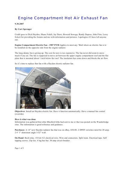
Engine Compartment Electric Fan - 1987 PT38 Applies to most any ‘Bird where an electric fan is to<br />
be installed on the opposite side from the engine radiator.<br />
The long skinny fan is giving up. The cost for new is too expensive. The fan never did seem to move<br />
much if any air. The fan is supposed to move air between the upper engine compartment roof and the flat<br />
plate that is mounted about 1 inch below the roof. The insulation has come down and blocks the air flow.<br />
So it’s time to replace that fan with a Hayden electric radiator fan.<br />
Objectives: Install an Hayden electric fan. Have it function automatically. Have a manual fan control<br />
(override).<br />
Here is what was done.<br />
Information was gathered that other Bluebird folks had sent to me or that was posted on the <strong>Wanderlodge</strong><br />
sites. The information is good reference and guidance.<br />
Purchases: A 14” new Hayden radiator fan that was on eBay, $50.00. 2 DPDT switches rated for 20 amp.<br />
2 4’ 1” aluminum angle 3/32” wall.<br />
On Hand: Bosh relay. #10 & #12 electrical wire. Wire end connectors. Split loom. Electrical tape. Self<br />
tapping screws. Zip ties. 4 lug bus bar. 30 amp circuit breaker.<br />
Page 1 of 5
Engine Compartment Hot Air Exhaust Fan<br />
Procedure:<br />
1. Mount the new fan on the aluminum angle, allowing for clearance in the engine bay. Mount the angle to<br />
the inside of the curb side grill using self tapping screws, one at each end. Drill a small hole first before<br />
driving in the self tapping screws.<br />
2. Disconnect the wires at the existing fan. Route the power wire in split loom to the battery charger bay.<br />
The wire/loom was run along the top of the engine bay and zip tied in place. And then down the engine<br />
compartment forward curb side wall with out zip ties for now.<br />
3. Route the fan wires in that same split loom, and run #12 wires (2) in that same split loom to join the fan<br />
wires, and connect the wires. Put split loom on the fan wires and use electrical tape to join the two looms.<br />
Route the wire/loom through existing holes in the sheet metal and into the battery bay. Zip tie the looms in<br />
place.<br />
4. Mount the circuit breaker in the battery bay using self tapping screws.<br />
5. Mount the Bosh relay in the bay using a self tapping screw.<br />
Page 2 of 5
Engine Compartment Hot Air Exhaust Fan<br />
6. Mount the 4 lug bus bar in the bay using self tapping screws.<br />
7. Made a switch bracket out of 1/8” aluminum flat stock 3” wide. Marked and drilled 2 mounting holes<br />
for the self tapping screws, and drill 2 ½” holes for the 2 DPDT switches. Then bend the aluminum flat<br />
stock to finish the bracket.<br />
8. Mount the switch bracket using self tapping screws.<br />
9. Connect the existing fan wire to the #85 trigger on the Bosh relay.<br />
10. Wire the circuit breaker silver terminal to the Bosh relay #30, and to the # 1 lug on the bus bar using<br />
#10 wires. Tighten the lug nut on the circuit breaker.<br />
Leave the bus bar lug nuts loose until later.<br />
11. Run a ground wire from within the battery bay to the #4 lug on the bus bar. Run a wire from the Bosh<br />
relay #86 to the #4 lug on the bus bar.<br />
12. Connect the two fan wires on the bus bar, one to #2 and one to #3 lugs on the bus bar.<br />
Use #12 wire from this point on.<br />
13. Prepare the 2 DPDT switches to reverse polarity and add the power and the ground wires. Then add<br />
wire to the center terminals.<br />
Wiring Reverse Polarity DPDT Switches - the corner pins diagonal from each other are connected with<br />
one end receiving a second wire for power, the other diagonal receiving a second wire for ground.<br />
14. Mount the switches in the switch bracket.<br />
I used the switch closer to the outside for the “automatic” control, and the inside switch for the manual<br />
control.<br />
15. Connect the power and ground wires of the Manual switch to the #1 and #4 bus bar lugs respectively.<br />
16. Connect the power wire of the other switch to the #87 lug on the Bosh relay. Connect the ground wire<br />
to the #4 bus bar lug.<br />
17. Connect the switches center terminal wires to the #2 and #3 bus bar lugs.<br />
Tighten the lug nuts on the bus bar.<br />
Page 3 of 5
Engine Compartment Hot Air Exhaust Fan<br />
18. Set both switches to off (center position).<br />
19. Connect a #10 wire from the battery charger spare terminal (mine has two hot lugs) to the copper side<br />
of the circuit breaker and tighten the lug nut. Or get power from somewhere in the battery bay.<br />
Testing:<br />
20. Lift up on the manual switch. The air flow should be outward. Go back to center position and let the<br />
fan stop turning. Push down on the switch. The air flow should be inward. Place the switch in the center<br />
position.<br />
21. Lift up on the automatic switch. Use a heat gun or a hair dryer and hold it near the Snap Disc<br />
thermostat that is located in the plate just under the engine compartment roof. The fan should come on in a<br />
few seconds. The air flow should be outward. Take away the heat and let the fan run until it shuts off<br />
automatically. Return the switch to the center position only if you plan to use the manual operation. See<br />
Normal Operation below.<br />
22. Use electrical twist nuts to protect the lugs on the circuit breaker and the bus bar.<br />
23. Use split loom to cover the wires best you can. Use zip ties to hold in shape/place.<br />
Page 4 of 5
Engine Compartment Hot Air Exhaust Fan<br />
Notes:<br />
The two switches can not be operated at the same time; one must always be in the center position. The<br />
workaround is to install Rectifiers (diodes) in the 2 center leads on one switch. That would prevent current<br />
from colliding and opening (tripping) the circuit breaker. I need to get a couple rectifiers and install them,<br />
but for now I just make sure that only one switch is active at a time.<br />
Mark by each switch which one is manual and which one is automatic.<br />
I made sure the up position for each switch exhausts air out, and the down position sucks air in. Switch the<br />
bus bar #2 and #3 wires for which ever switch needs it.<br />
Air flow – It is reported that when parked, use the manual switch to turn on the fan to suck air in as that<br />
seems to do a better job of cooling down the engine compartment and the bedroom above it. Since the<br />
automatic function will shut down the fan as soon as the Snap Disc thermostat cools, and the manually<br />
switch leaves the fan running until you want it turned off.<br />
Normal Operation: Normal operation is the manual switch in the center position and the automatic<br />
switch in the up position when going down the road.<br />
Page 5 of 5