MT-4R and MT-4D P25 Digital and Analog Radio Systems - Daniels ...
MT-4R and MT-4D P25 Digital and Analog Radio Systems - Daniels ...
MT-4R and MT-4D P25 Digital and Analog Radio Systems - Daniels ...

You also want an ePaper? Increase the reach of your titles
YUMPU automatically turns print PDFs into web optimized ePapers that Google loves.
20<br />
Chapter 4: <strong>P25</strong> System Block Diagrams<br />
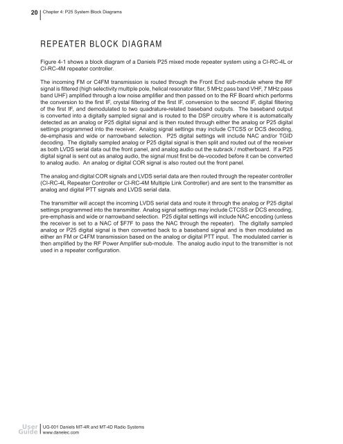
REPEATER BLOCK DIAGRAM<br />
Figure 4-1 shows a block diagram of a <strong>Daniels</strong> <strong>P25</strong> mixed mode repeater system using a CI-RC-4L or<br />
CI-RC-4M repeater controller.<br />
The incoming FM or C4FM transmission is routed through the Front End sub-module where the RF<br />
signal is fi ltered (high selectivity multiple pole, helical resonator fi lter, 5 MHz pass b<strong>and</strong> VHF, 7 MHz pass<br />
b<strong>and</strong> UHF) amplifi ed through a low noise amplifi er <strong>and</strong> then passed on to the RF Board which performs<br />
the conversion to the fi rst IF, crystal fi ltering of the fi rst IF, conversion to the second IF, digital fi ltering<br />
of the fi rst IF, <strong>and</strong> demodulated to two quadrature-related baseb<strong>and</strong> outputs. The baseb<strong>and</strong> output<br />
is converted into a digitally sampled signal <strong>and</strong> is routed to the DSP circuitry where it is automatically<br />
detected as an analog or <strong>P25</strong> digital signal <strong>and</strong> is then routed through either the analog or <strong>P25</strong> digital<br />
settings programmed into the receiver. <strong>Analog</strong> signal settings may include CTCSS or DCS decoding,<br />
de-emphasis <strong>and</strong> wide or narrowb<strong>and</strong> selection. <strong>P25</strong> digital settings will include NAC <strong>and</strong>/or TGID<br />
decoding. The digitally sampled analog or <strong>P25</strong> digital signal is then split <strong>and</strong> routed out of the receiver<br />
as both LVDS serial data out the front panel, <strong>and</strong> analog audio out the subrack / motherboard. If a <strong>P25</strong><br />
digital signal is sent out as analog audio, the signal must fi rst be de-vocoded before it can be converted<br />
to analog audio. An analog or digital COR signal is also routed out the front panel.<br />
The analog <strong>and</strong> digital COR signals <strong>and</strong> LVDS serial data are then routed through the repeater controller<br />
(CI-RC-4L Repeater Controller or CI-RC-4M Multiple Link Controller) <strong>and</strong> are sent to the transmitter as<br />
analog <strong>and</strong> digital PTT signals <strong>and</strong> LVDS serial data.<br />
The transmitter will accept the incoming LVDS serial data <strong>and</strong> route it through the analog or <strong>P25</strong> digital<br />
settings programmed into the transmitter. <strong>Analog</strong> signal settings may include CTCSS or DCS encoding,<br />
pre-emphasis <strong>and</strong> wide or narrowb<strong>and</strong> selection. <strong>P25</strong> digital settings will include NAC encoding (unless<br />
the receiver is set to a NAC of $F7F to pass the NAC through the repeater). The digitally sampled<br />
analog or <strong>P25</strong> digital signal is then converted back to a baseb<strong>and</strong> signal <strong>and</strong> is then modulated as<br />
either an FM or C4FM transmission based on the analog or digital PTT input. The modulated carrier is<br />
then amplifi ed by the RF Power Amplifi er sub-module. The analog audio input to the transmitter is not<br />
used in a repeater confi guration.<br />
User<br />
Guide<br />
UG-001 <strong>Daniels</strong> <strong>MT</strong>-<strong>4R</strong> <strong>and</strong> <strong>MT</strong>-<strong>4D</strong> <strong>Radio</strong> <strong>Systems</strong><br />
www.danelec.com