Floor Standing Air Conditioner SVC MANUAL ... - Jordans Manuals
Floor Standing Air Conditioner SVC MANUAL ... - Jordans Manuals
Floor Standing Air Conditioner SVC MANUAL ... - Jordans Manuals

You also want an ePaper? Increase the reach of your titles
YUMPU automatically turns print PDFs into web optimized ePapers that Google loves.
Internal Use Only<br />
http://biz.lgservice.com<br />
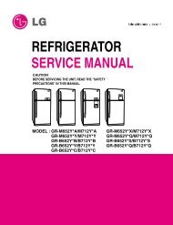
<strong>Floor</strong> <strong>Standing</strong> <strong>Air</strong> <strong>Conditioner</strong><br />
<strong>SVC</strong> <strong>MANUAL</strong>(Exploded View)<br />
MODEL : LP-K Series<br />
CAUTION<br />
Before Servicing the unit, read the safety precautions in General <strong>SVC</strong> manual.<br />
Only for authorized service personnel.
Contents<br />
Functions 3<br />
Product Specifications 6<br />
Dimensions 7<br />
Refrigeration Cycle Diagram 7<br />
Wiring Diagram 8<br />
Operation Details 12<br />
Installation of Indoor, Outdoor Unit 19<br />
Test Running 30<br />
3-way Valve 32<br />
Cycle Troubleshooting Guide 38<br />
Electronic Parts Troubleshooting Guide 39<br />
Electronic Control Device 42<br />
Schematic Diagram 43<br />
Exploded View 44<br />
Copyright ©2007 LG Electronics. Inc. All right reserved.<br />
Only for training and service purposes<br />
- 2 -<br />
LGE Internal Use Only
Functions<br />
Indoor Unit<br />
Power Switch ON/OFF<br />
Operation Mode Control<br />
• Cooling, Heating, Soft Dry, Fan<br />
Indoor Fan Speed Control<br />
• High, Low<br />
Jet Cool<br />
• Speed Cooling operates super high fan speed in cooling mode<br />
Energy Saving<br />
• Cooling Mode only<br />
Room Temperature control<br />
• Maintains the room temperature in accordance with the Setting Temp.<br />
• Up: up to 30°C<br />
• Down: down to 16°C<br />
Sensing Heat Exchanger Temperature<br />
• Heat exchanger temperature sensor (Thermistor)<br />
Soft Dry Operation Mode<br />
• Intermittent operation of fan at low speed.<br />
Time Delay Safety Control<br />
• Restarting is inhibited for approx. 3 minutes.<br />
Fan Operation<br />
• Used to circulate room air without cooling.<br />
AutoRestart<br />
• The power comes on again after a power failure.<br />
Copyright ©2007 LG Electronics. Inc. All right reserved.<br />
Only for training and service purposes<br />
- 3 -<br />
LGE Internal Use Only
Remote Control<br />
Operation ON/OFF<br />
Cooling Operation Mode<br />
Heating Operation Mode<br />
Sot Dry Operation Mode<br />
• Intermittent operation of fan at low speed.<br />
Fan Operation<br />
• Used to circulate room air without cooling.<br />
Timer Control<br />
• OFF Timer (1, 2, 3,......7 hour)<br />
Jet Cool<br />
• Speed cooling operates super high fan speed in cooling mode.<br />
Energy Saving<br />
<strong>Air</strong>flow Direction Control<br />
• <strong>Air</strong>flow direction Auto-swing and Manual Contol.<br />
Room Temperature Control<br />
• Up: up to 30°C<br />
• Down: down to 16°C<br />
• High, Low<br />
Indoor Fan speed control<br />
Copyright ©2007 LG Electronics. Inc. All right reserved.<br />
Only for training and service purposes<br />
- 4 -<br />
LGE Internal Use Only
Outdoor Unit<br />
Deice Control<br />
• De-ice PCB<br />
Outdoor Fan Speed Control<br />
• One speed<br />
Sensing Heat Exchanger Temperature<br />
• Heat exchanger temperature sensor (Thermistor)<br />
Sensing Discharge Pressure For Compressor<br />
• Discharge pressure sensor (High Pressure Switch)<br />
Copyright ©2007 LG Electronics. Inc. All right reserved.<br />
Only for training and service purposes<br />
- 5 -<br />
LGE Internal Use Only
Product Specifications<br />
• HEAT PUMP MODELS<br />
MODEL<br />
ITEMS<br />
UNIT<br />
POWER SUPPLY Ø, V, Hz<br />
COOLING CAPACITY<br />
Btu/hr<br />
HEATING CAPACITY<br />
Btu/hr<br />
(Incl. elec. Heater)<br />
POWER INPUT COOLING W<br />
HEATING W<br />
RUNNING COOLING A<br />
CURRENT HEATING A<br />
MODEL<br />
MAKER<br />
TYPE<br />
COMPRESSOR CAPACITY Btu/hr<br />
INPUT (KW)<br />
LRA<br />
A<br />
NOISE LEVEL INDOOR dB(A)<br />
OUTDOOR dB(A)<br />
AIR INDOOR CFM/CMM<br />
CIRCULATION OUTDOOR CFM/CMM<br />
REFRIGERANT (R-22)<br />
OZ(kg)<br />
HEAT INDOOR R/C/FPI<br />
EXCHANGER OUTDOOR R/C/FPI<br />
FAN INDOOR TYPE<br />
OUTDOOR TYPE<br />
ROOM TEMPERATURE CONTROL<br />
WIDTH<br />
INDOOR HEIGHT inch(mm)<br />
DEPTH<br />
D<br />
I<br />
M<br />
E<br />
N<br />
SI<br />
O<br />
WIDTH<br />
N OUTDOOR HEIGHT inch(mm)<br />
S<br />
DEPTH<br />
NET WEIGHT<br />
INDOOR Ib(kg)<br />
OUTDOOR Ib(kg)<br />
CONNECTIONS<br />
LIQUID inch(mm)<br />
GAS inch(mm)<br />
LP-K3063ZA/ZL/HA/HB/HL/HM<br />
LP-K30638A<br />
1, 220-240, 50<br />
27,800<br />
27,800 + (2kw)<br />
2,750<br />
2,450<br />
12.5<br />
11.2<br />
H23B33SABHA<br />
BRISTOL<br />
RECIPRO<br />
28,300<br />
2.76<br />
76<br />
48<br />
58<br />
670/19<br />
2,225/63<br />
88.1(2.5)<br />
3/22/18<br />
2/30/16<br />
SIROCO<br />
PROPELLER<br />
MICOM CONTROL<br />
19.68(500)<br />
70.86(1800)<br />
12.59(320)<br />
34.25(870)<br />
31.49(800)<br />
12.59(320)<br />
88.18(40)<br />
143.2(65)<br />
3/8"(Ø9.52)<br />
5/8"(Ø15.88)<br />
LP-K3023HA/HL<br />
1, 220,60<br />
27,800<br />
27,800<br />
3,400<br />
3,200<br />
16<br />
14.5<br />
AWG5532EXN<br />
TELUMSEH<br />
RECIPRO<br />
31,500<br />
3.3<br />
90<br />
48<br />
58<br />
670/19<br />
2,225/63<br />
82.9(2.35)<br />
3/22/18<br />
2/30/16<br />
SIROCO<br />
PROPELLER<br />
MICOM CONTROL<br />
19.68(500)<br />
70.86(1800)<br />
12.59(320)<br />
34.25(870)<br />
31.49(800)<br />
12.59(320)<br />
88.18(40)<br />
143.2(65)<br />
3/8"(Ø9.52)<br />
5/8"(Ø15.88)<br />
Copyright ©2007 LG Electronics. Inc. All right reserved.<br />
Only for training and service purposes<br />
- 6 -<br />
LGE Internal Use Only
Product Specifications<br />
• COOLING ONLY MODEL<br />
MODEL LP-K3023CA/CL/<br />
LP-K2063CA/CL/AA<br />
ITEMS<br />
UNIT<br />
CM/AA<br />
POWER SUPPLY Ø, V, Hz<br />
1, 220-240, 50<br />
1, 220,60<br />
COOLING CAPACITY<br />
Btu/hr 20,000<br />
27,800<br />
HEATING CAPACITY<br />
Btu/hr<br />
-<br />
-<br />
(Incl. elec. Heater)<br />
POWER INPUT COOLING W<br />
1,900<br />
3,400<br />
HEATING W<br />
-<br />
-<br />
RUNNING COOLING A<br />
9<br />
16<br />
CURRENT HEATING A<br />
-<br />
-<br />
MODEL<br />
MAKER<br />
TYPE<br />
FX24QP12CA<br />
LG<br />
SCROLL<br />
AWG5532EXN<br />
TECUMSHE<br />
RECIPRO<br />
COMPRESSOR CAPACITY Btu/hr 20,000<br />
31,500<br />
INPUT (KW)<br />
1.94<br />
3.3<br />
LRA<br />
A<br />
53<br />
90<br />
NOISE LEVEL INDOOR dB(A)<br />
45<br />
48<br />
OUTDOOR dB(A)<br />
53<br />
58<br />
AIR INDOOR CFM/CMM 600/17<br />
670/19<br />
CIRCULATION OUTDOOR CFM/CMM 2,046/58<br />
2,046/58<br />
REFRIGERANT (R-22)<br />
OZ(kg) 55(1.56)<br />
63.5(1.8)<br />
HEAT INDOOR R/C/FPI 2/22/18<br />
3/22/18<br />
EXCHANGER OUTDOOR R/C/FPI 2/24/18<br />
2/24/18<br />
FAN INDOOR TYPE SIROCO<br />
SIROCO<br />
OUTDOOR TYPE PROPELLER PROPELLER<br />
ROOM TEMPERATURE CONTROL<br />
WIDTH<br />
MICOM CONTROL<br />
19.68(500)<br />
MICOM CONTROL<br />
19.68(500)<br />
INDOOR HEIGHT inch(mm) 70.86(1800)<br />
70.86(1800)<br />
DEPTH<br />
12.59(320)<br />
12.59(320)<br />
D<br />
I<br />
M<br />
E<br />
N<br />
SI<br />
O<br />
WIDTH<br />
34.25(870)<br />
34.25(870)<br />
N OUTDOOR HEIGHT inch(mm) 25.78(655)<br />
25.78(655)<br />
S<br />
DEPTH<br />
12.59(320)<br />
12.59(320)<br />
NET WEIGHT<br />
INDOOR Ib(kg) 88.18(40)<br />
88.18(40)<br />
OUTDOOR Ib(kg) 138.6(63)<br />
138.6(63)<br />
CONNECTIONS<br />
LIQUID inch(mm) 1/4"(Ø6.35)<br />
3/8"(Ø9.52)<br />
GAS inch(mm) 5/8"(Ø15.88) 5/8"(Ø15.88)<br />
LP-K3063CA/CL/<br />
CM/AA<br />
1, 220-240, 50<br />
27,800<br />
-<br />
2,850<br />
-<br />
13<br />
-<br />
H23B33SABHA<br />
BRISTOL<br />
RECIPRO<br />
28,300<br />
2.76<br />
76<br />
48<br />
58<br />
670/19<br />
2,046/58<br />
60.0(1.7)<br />
3/22/18<br />
2/24/18<br />
SIROCO<br />
PROPELLER<br />
MICOM CONTROL<br />
19.68(500)<br />
70.86(1800)<br />
12.59(320)<br />
34.25(870)<br />
25.78(655)<br />
12.59(320)<br />
88.18(40)<br />
138.6(63)<br />
3/8"(Ø9.52)<br />
5/8"(Ø15.88)<br />
LP-K4023CA/CL/AA<br />
1, 220,60<br />
36,000<br />
-<br />
3,500<br />
-<br />
17<br />
-<br />
CR38K6-PFV-502<br />
COPELAND<br />
RECIPRO<br />
38,200<br />
3.52<br />
102<br />
52<br />
62<br />
741/21<br />
2,225/63<br />
84.6(2.4)<br />
3/22/18<br />
2/30/18<br />
SIROCO<br />
PROPELLER<br />
MICOM CONTROL<br />
19.68(500)<br />
70.86(1800)<br />
12.59(320)<br />
34.25(870)<br />
31.49(800)<br />
12.59(320)<br />
88.18(40)<br />
147.7(67)<br />
3/8"(Ø9.52)<br />
5/8"(Ø15.88)<br />
Copyright ©2007 LG Electronics. Inc. All right reserved.<br />
Only for training and service purposes<br />
- 7 -<br />
LGE Internal Use Only
Dimensions<br />
Indoor Unit<br />
Outdoor Unit<br />
<strong>Air</strong> Outlet Vent<br />
Remote Signal<br />
Receptor<br />
<strong>Air</strong> Intake Vent<br />
(Rear)<br />
<strong>Air</strong> Inlet Vent<br />
<strong>Air</strong> Outlet<br />
Vent<br />
Refrigeration Cycle Diagram<br />
INDOOR UNIT<br />
OUTDOOR UNIT<br />
CAPILLARY TUBE<br />
LIQUID SIDE<br />
CHECK VALVE<br />
HEAT<br />
EXCHANGER<br />
CAPILLARY TUBE<br />
BY PATH CAPILLARY TUBE<br />
HEAT<br />
EXCHANGER<br />
GAS SIDE<br />
REVERSING<br />
VALVE<br />
COMPRESSOR<br />
COOLING<br />
HEATING<br />
Copyright ©2007 LG Electronics. Inc. All right reserved.<br />
Only for training and service purposes<br />
- 8 -<br />
LGE Internal Use Only
Wiring Diagram<br />
(1) LP-K3063ZA/ZL/HA/HL/HM/ZM, LP-K30638A<br />
POWER<br />
SUPPLY<br />
WIRING DIAGRAM<br />
OUTDOOR UNIT INDOOR UNIT<br />
1(L) 2(N)<br />
BK<br />
BL<br />
BR<br />
BR<br />
BR<br />
BL<br />
4 2<br />
8 6<br />
1 0<br />
POWER<br />
RELAY<br />
BL<br />
BR<br />
FUSE(250V,5A)<br />
WH<br />
L1<br />
PIPE TH<br />
L3<br />
YL<br />
L2<br />
BR<br />
BK<br />
BK<br />
BK<br />
BR<br />
BL<br />
1<br />
2<br />
BL<br />
POWER<br />
SUPPLY<br />
HEATER<br />
6 8<br />
2 4<br />
0 1<br />
RD<br />
FUSE<br />
(250V/3.15L)<br />
FAN<br />
MOTOR<br />
OR<br />
WH<br />
RY-BIMETAL<br />
RY-BIMETAL<br />
RY-BIMETAL<br />
BKBL<br />
RD<br />
GN/YL<br />
BR<br />
YL<br />
RY-BIMETAL<br />
RY-BIMETAL<br />
ELECTRIC<br />
HEATER<br />
ZA,ZL<br />
(HEATER<br />
MODEL ONLY)<br />
CAPA<br />
-CITOR SM<br />
S<br />
R<br />
T/B1<br />
CAPACITOR<br />
OR<br />
CAPACITOR<br />
RD BL<br />
OR YL<br />
C<br />
FAN<br />
MOTOR<br />
HIGH PRESS<br />
COMP<br />
SWITCH<br />
BK BK<br />
T/B2<br />
SUMP HEATER<br />
WH<br />
3 5 4 6<br />
3 5 4 6<br />
RY-COMP<br />
RY-S/HIGH<br />
RY-HIGH<br />
RY-MID<br />
RY-LO<br />
RY-AIRC<br />
RY-4WAY<br />
RY-EH<br />
MAIN PCB ASM<br />
RY-SYNC<br />
EVAP<br />
TH<br />
REVERSING<br />
VALVE<br />
BK<br />
CN1<br />
BL<br />
BL<br />
CN1<br />
DISPLAY PCB ASM<br />
ROOM<br />
TH<br />
NOTE<br />
BL : BLUE<br />
BK : BLACK<br />
BR : BROWN<br />
RD : RED<br />
BK<br />
OR : ORANGE<br />
WH:<br />
WHITE<br />
YL : YELLOW<br />
GN/YL : GREEN/YELLOW<br />
FUSE(250V,5A)<br />
GN/YL<br />
: OPTIONAL PARTS<br />
* HIDDEN LINE( ------- ) : FIELD WIRING<br />
ZA,HA<br />
(AIR CLEANER<br />
MODEL ONLY)<br />
DOOR S/W<br />
HVB<br />
ASM<br />
BK<br />
WH<br />
RD<br />
A/CL<br />
UNIT<br />
P/No.;3854A20172A<br />
(2) LP-K3063ZA, LP-K30638A(Australia only)<br />
OUTDOOR WIRING DIAGRAM<br />
3 3 S/Capacitor<br />
4 4<br />
BL CN- CN-<br />
RD<br />
COMP S/Capa<br />
RD<br />
CN-POWER<br />
R<br />
RD<br />
CAPACITOR<br />
COMP S<br />
C<br />
SUMP<br />
HEATER<br />
BK<br />
BK<br />
BR<br />
POWER<br />
RELAY<br />
FUSE 5A<br />
BR<br />
BR<br />
FUSE 5A<br />
BL<br />
BL<br />
BL BL<br />
4 8 1<br />
2 6 0<br />
BL<br />
BR<br />
BR<br />
BL<br />
1 2 3 4<br />
BL<br />
BR<br />
FAN<br />
MOTOR<br />
REVERSING<br />
VALVE<br />
BK<br />
5 6<br />
YL<br />
OR<br />
BK<br />
BK<br />
WH<br />
BK<br />
BK<br />
TERMINAL<br />
BLOCK<br />
CAPACITOR<br />
L3 L2 L1<br />
DEICER<br />
PCB<br />
YL<br />
OR<br />
HIGH PRESSURE<br />
SWITCH<br />
BK<br />
TERMINAL<br />
BLOCK<br />
POWER<br />
INPUT<br />
TO INDOOR UNIT<br />
3854AP2708X<br />
Copyright ©2007 LG Electronics. Inc. All right reserved.<br />
Only for training and service purposes<br />
- 9 -<br />
LGE Internal Use Only
(3) LP-K3063CA/CL/CM<br />
CIRCUIT DIAGRAM<br />
INDOOR UNIT<br />
OUTDOOR UNIT<br />
HIDDEN LINE: FIELD WIRING<br />
GN/YL<br />
RD<br />
BL<br />
BR<br />
6 5 4 3<br />
POWER INPUT<br />
FUSE<br />
(250V/3.15L)<br />
SM<br />
F1<br />
BR<br />
1<br />
2 3 4<br />
5 6<br />
TERMINAL<br />
BLOCK(6P)<br />
GN/YL<br />
RY-AIRC<br />
RY-S/HIGH<br />
RY-HIGH<br />
RY-MID<br />
RY-LO<br />
RY-COMP<br />
RY-SYNC<br />
OR<br />
WH<br />
BK<br />
BL<br />
RD<br />
BR<br />
Cr<br />
YL<br />
FAN<br />
MOTER<br />
BR<br />
BL<br />
F2<br />
BL<br />
POWER<br />
RELAY<br />
BR BL BR<br />
2 6 0<br />
4 8 1<br />
BK<br />
BK<br />
OR<br />
DOOR S/W<br />
CN-DISP(1)<br />
MAIN PCB ASM<br />
EVAP<br />
TH<br />
GN/YL<br />
BR RD<br />
BL<br />
BL<br />
BL<br />
BK OR YL<br />
BK RD<br />
BK<br />
HVB<br />
ASM<br />
BK<br />
WH<br />
RD<br />
CN1<br />
ROOM<br />
DISPLAY TH<br />
PCB ASM<br />
A/CL<br />
UNIT<br />
CA<br />
(AIR CLEANER<br />
MODEL<br />
ONLY)<br />
NOTE<br />
BL : BLUE COMP.<br />
BK : BLACK<br />
BR : BROWN<br />
RD : RED<br />
OR : ORANGE<br />
WH:<br />
WHITE<br />
YL : YELLOW<br />
GN/YL:GREEN/YELLOW<br />
: OPTIONAL PARTS<br />
C<br />
S<br />
R<br />
CAPACITOR<br />
FAN<br />
MOTOR<br />
CAPACITOR<br />
P/No.; 3854A20172B<br />
(4) LP-K4023CA/CL/CM<br />
CIRCUIT DIAGRAM<br />
INDOOR UNIT<br />
OUTDOOR UNIT<br />
BK<br />
WH<br />
RD<br />
BK<br />
WH<br />
RD<br />
DOOR S/W<br />
BK RD<br />
HVB<br />
ASM<br />
BK<br />
BK<br />
WH<br />
RD<br />
CN-DISP(1)<br />
CN1<br />
DISPLAY<br />
PCB ASM<br />
FUSE<br />
(250V 3.15A)<br />
CN-DISP(2)<br />
CN2<br />
A/CL<br />
ASM<br />
RY-S/HIGH<br />
RY-HIGH<br />
RY-MID<br />
RY-LD<br />
MAIN PCB ASM<br />
ROOM<br />
TH<br />
RY-COMP<br />
RY-SYNC<br />
EVAP<br />
TH<br />
OR<br />
WH<br />
BK<br />
BL<br />
RD<br />
SM<br />
BR<br />
Ci<br />
YL<br />
Fan<br />
Motor<br />
GN/YL<br />
WH<br />
S<br />
R<br />
C<br />
CM<br />
BR<br />
BK<br />
63H<br />
RD<br />
BK<br />
RD<br />
FUSE<br />
250V<br />
5 A<br />
Tmo1<br />
PTCR<br />
BK<br />
WH<br />
1 2 3 5 A 4 5 6<br />
POWER SUPPLY<br />
1ø, 220V, 60Hz<br />
Cr<br />
WH<br />
WH<br />
GN/YL<br />
RD<br />
Co<br />
OR BK<br />
BR<br />
T1<br />
L1<br />
T2<br />
L2<br />
52C<br />
A<br />
B<br />
WH<br />
FUSE<br />
250V<br />
BK<br />
OR<br />
Tmo2<br />
FMo<br />
BK<br />
YL<br />
RD<br />
WH<br />
RD<br />
WH<br />
BK<br />
Copyright ©2007 LG Electronics. Inc. All right reserved.<br />
Only for training and service purposes<br />
- 10 -<br />
LGE Internal Use Only
(5) LP-K3023HA/HL/HM<br />
CIRCUIT DIAGRAM<br />
INDOOR UNIT<br />
OUTDOOR UNIT<br />
HIDDEN LINE: FIELD WIRING<br />
NOTE<br />
DOOR S/W<br />
RY-AIRC<br />
CN-DISP(1)<br />
FUSE<br />
(250V/3.15L)<br />
RY-S/HIGH<br />
RY-HIGH<br />
RY-MID<br />
RY-LO<br />
RY-COMP<br />
MAIN PCB ASM<br />
RY-REVERSING<br />
VALVE<br />
GN/YL<br />
BL<br />
RD<br />
BL<br />
BR<br />
RY-SYNC<br />
EVAP<br />
TH<br />
OR<br />
WH<br />
BK<br />
BL<br />
RD<br />
SM<br />
BR<br />
Cr<br />
YL<br />
FAN<br />
MOTER<br />
GN/YL<br />
6 5 4 3<br />
POWER<br />
INPUT<br />
F1<br />
BR<br />
BR<br />
BL<br />
F2<br />
BL<br />
POWER<br />
RELAY<br />
1<br />
BR BL BL<br />
BL<br />
2 3 4 5 6<br />
2 6 0<br />
4 8 1<br />
BR<br />
TERMINAL<br />
BLOCK(6P)<br />
WH<br />
BK<br />
L1 L2 L3<br />
DEICER<br />
P.C.B<br />
BK<br />
BK<br />
OR<br />
BL : BLUE<br />
BK : BLACK<br />
BR : BROWN<br />
RD : RED<br />
OR : ORANGE<br />
WH:<br />
WHITE<br />
YL : YELLOW<br />
GN/YL: GREEN/YELLOW<br />
: OPTIONAL PARTS<br />
REVERSING<br />
VALVE<br />
T/B2 BK<br />
YL<br />
T/B1<br />
BK<br />
HIGH PRESS<br />
SWITCH<br />
BK RD<br />
BK<br />
HVB<br />
ASM<br />
BK<br />
WH<br />
RD<br />
CN1<br />
DISPLAY ROOM<br />
PCB ASM TH<br />
A/CL<br />
UNIT<br />
HA<br />
(AIR CLEANER<br />
MODEL<br />
ONLY)<br />
BR RD BL<br />
S<br />
C R<br />
COMP.<br />
CAPACITOR<br />
BK OR YL<br />
FAN<br />
MOTOR<br />
CAPACITOR<br />
OR<br />
P/No.; 3854A20172C<br />
(6) LP-K3023CA/CL/CM/AA<br />
CIRCUIT DIAGRAM<br />
INDOOR UNIT<br />
OUTDOOR UNIT<br />
HIDDEN LINE: FIELD WIRING<br />
GN/YL<br />
RD<br />
BL<br />
BR<br />
6 5 4 3<br />
POWER INPUT<br />
FUSE<br />
(250V/3.15L)<br />
SM<br />
F1<br />
BR<br />
1<br />
2 3 4<br />
5 6<br />
TERMINAL<br />
BLOCK(6P)<br />
GN/YL<br />
RY-AIRC<br />
RY-S/HIGH<br />
RY-HIGH<br />
RY-MID<br />
RY-LO<br />
RY-COMP<br />
RY-SYNC<br />
OR<br />
WH<br />
BK<br />
BL<br />
RD<br />
BR<br />
Cr<br />
YL<br />
FAN<br />
MOTER<br />
BR<br />
BL<br />
F2<br />
BL<br />
POWER<br />
RELAY<br />
BR BL BR<br />
2 6 0<br />
4 8 1<br />
BK<br />
BK<br />
OR<br />
DOOR S/W<br />
CN-DISP(1)<br />
MAIN PCB ASM<br />
EVAP<br />
TH<br />
GN/YL<br />
BR RD BL<br />
BL<br />
BL<br />
BK OR YL<br />
BK RD<br />
BK<br />
HVB<br />
ASM<br />
BK<br />
WH<br />
RD<br />
CN1<br />
ROOM<br />
DISPLAY TH<br />
PCB ASM<br />
A/CL<br />
UNIT<br />
CA<br />
(AIR CLEANER<br />
MODEL<br />
ONLY)<br />
NOTE<br />
BL : BLUE COMP.<br />
BK : BLACK<br />
BR : BROWN<br />
RD : RED<br />
OR : ORANGE<br />
WH:<br />
WHITE<br />
YL : YELLOW<br />
GN/YL:GREEN/YELLOW<br />
: OPTIONAL PARTS<br />
C<br />
S<br />
R<br />
CAPACITOR<br />
FAN<br />
MOTOR<br />
CAPACITOR<br />
P/No.; 3854A20172D<br />
Copyright ©2007 LG Electronics. Inc. All right reserved.<br />
Only for training and service purposes<br />
- 11 -<br />
LGE Internal Use Only
Operation Details<br />
(1) The function of main control<br />
1. Time Delay Safety Control<br />
3min The compressor is ceased for 3 minutes to balance the pressure in the refrigeration cycle.<br />
(Protection of compressor)<br />
3sec The indoor fan is ceased for 3 seconds to prevent relay noise.<br />
(Protection of fan relay and micro chip)<br />
30sec The 4-way valve is ceased for 30 sec. to prevent the refrigerant-gas abnormal noise when the Heating<br />
operation is OFF or switched to the other operation mode.<br />
2. <strong>Air</strong>flow Direction Control<br />
This function is to swing the louver left and right automatically and to set it at the desired position.<br />
The procedure is as the following.<br />
1st : Press the ON/OFF Button to operate the product.<br />
2nd : Press the <strong>Air</strong>flow Direction Control Button to swing the louver left and right automatically.<br />
(Remote controller)<br />
3rd : Repress the <strong>Air</strong>flow Direction Control Button to set the louver as the desired position.<br />
(Remote controller)<br />
3. Cooling Mode Operation<br />
When selecting the Cooling( ) Mode Operation, the unit will operate according to the setting by the<br />
controller and the operation diagram is as following.<br />
Intake <strong>Air</strong> temp.<br />
Setting Temp. +1°C<br />
(Compressor ON)<br />
Setting Temp. -1°C<br />
(Compressor OFF)<br />
More than<br />
3 minutes<br />
More than<br />
3 minutes<br />
Indoor Fan Speed<br />
Selecting<br />
fan speed<br />
Selecting<br />
fan speed<br />
Selecting<br />
fan speed<br />
Selecting<br />
fan speed<br />
Selecting<br />
fan speed<br />
Compressor ON OFF ON OFF ON<br />
4. Off Timer Function<br />
This function is to set the time of stopping the unit operation.<br />
The procedure is as the following.<br />
1st: Press the timer set button on the Remocon.<br />
2nd: The buzzer sounds and then the display window shows the Off-Time to be set as<br />
- The Off-Time is shifted as the following by each press.<br />
....<br />
- If you select ' ', the Off-Timer function will be cancelled.<br />
- During Off-Timer Operation, if you repress the timer set button, the rest time will be displayed.<br />
Copyright ©2007 LG Electronics. Inc. All right reserved.<br />
Only for training and service purposes<br />
- 12 -<br />
LGE Internal Use Only
5. Heating Mode Operation<br />
The unit will operate according to the setting by the remote controller and the operation diagram is shown as<br />
following.<br />
Intake <strong>Air</strong> Temp.<br />
Setting Temp. +1°C<br />
(Compressor OFF)<br />
A<br />
A<br />
Setting Temp.<br />
(Compressor ON)<br />
Setting Temp. -1°C<br />
minimum<br />
minimum<br />
minimum<br />
Hot<br />
Start<br />
minimum<br />
10sec.<br />
10sec.<br />
10sec.<br />
10sec.<br />
Indoor Fan Speed<br />
OFF<br />
Selecting<br />
fan speed<br />
LOW<br />
OFF<br />
Selecting<br />
fan speed<br />
LOW<br />
OFF<br />
Compressor<br />
ON<br />
OFF ON OFF<br />
Electric Heater(Option)<br />
OFF ON<br />
OFF<br />
ON OFF<br />
• A point: The indoor pipe temperature to be less then 35°C & Discharge air Temperature to be less than 29°C.<br />
The indoor fan operates for minimum 10sec. even if falls lower than 34°C.<br />
During heating operation, the operating procedure of the indoor fan is as the following.<br />
Stop(VI)<br />
Low(V)<br />
Selecting Fan Speed(IV)<br />
39˚C<br />
Discharge <strong>Air</strong> Temp.<br />
34˚C<br />
Indoor Pipe Temp.<br />
28˚C<br />
26˚C<br />
(Hot-Start Release Point)<br />
Heating Start<br />
Stop(I)<br />
(Hot-Start Operating)<br />
Low(II)<br />
Selecting Fan Speed(III)<br />
Step Indoor fan speed Pipe temp. <strong>Air</strong> discharge temp.<br />
Off<br />
28 C(Hot start operating)<br />
Low 28 C < 39°C<br />
Selecting speed 28 C ≥ 39°C<br />
Selecting speed 28 C > 34°C<br />
Low 26 C ≤ 34°C<br />
Off<br />
26 C<br />
Copyright ©2007 LG Electronics. Inc. All right reserved.<br />
Only for training and service purposes<br />
- 13 -<br />
LGE Internal Use Only
5-1. Heating Mode Operation<br />
The unit will operate according to the setting by the remote controller and the operation diagram is shown as<br />
following.<br />
Intake <strong>Air</strong> Temp.<br />
Setting Temp. +1°C<br />
(Compressor OFF)<br />
A<br />
A<br />
Setting Temp.<br />
(Compressor ON)<br />
Setting Temp. -1°C<br />
minimum<br />
minimum<br />
Hot<br />
Start<br />
minimum<br />
10sec.<br />
10sec.<br />
1min<br />
Indoor Fan Speed<br />
OFF<br />
LOW<br />
Selecting<br />
fan speed<br />
LOW<br />
OFF<br />
Selecting<br />
fan speed<br />
LOW<br />
OFF<br />
Compressor<br />
ON<br />
OFF ON OFF<br />
Electric Heater(Option)<br />
OFF ON<br />
OFF<br />
ON OFF<br />
• A point: The indoor pipe temperature to be less than B°C.<br />
The indoor fan operates for minimum 10sec. even if the indoor pipe temperature falls lower than B°C.<br />
During heating operation, the operating procedure of the indoor fan is as the following.<br />
Stop(VI)<br />
Low(V)<br />
Selecting Fan Speed(IV)<br />
Indoor Pipe Temp.<br />
C˚C<br />
D˚C<br />
Heat OFF<br />
Heat ON<br />
Indoor Temp. Indoor Temp.<br />
15°C 20°C 20°C 15°C 20°C 20°C<br />
C°C 32°C 34°C 36°C 30°C 31°C 33°C<br />
D°C 28°C 30°C 32°C 26°C 28°C 30°C<br />
B°C 27°C 29°C 31°C - - -<br />
22˚C<br />
20˚C<br />
Heating Start<br />
Stop(I)<br />
(Hot-Start Operating)<br />
(Hot-Start Release Point)<br />
Low(II)<br />
Selecting Fan Speed(III)<br />
Step Indoor fan speed Pipe temp.<br />
Off<br />
≤22°C(Hot start operating)<br />
Low<br />
≥22°C<br />
Selecting speed<br />
≥C°C<br />
Low<br />
≤D°C<br />
Off<br />
≤20°C<br />
Copyright ©2007 LG Electronics. Inc. All right reserved.<br />
Only for training and service purposes<br />
- 14 -<br />
LGE Internal Use Only
6. Hot-Start Control<br />
• The indoor fan stops until the evaporator piping temperature will be reached to 28°C.<br />
• During heating operation, if piping temperatures fall below 26°C fan stops.<br />
• The operation diagram is as following.<br />
INDOOR PIPE<br />
TEMP.<br />
28°C<br />
Maximum<br />
1min<br />
26°C<br />
INDOOR FAN<br />
SPEED<br />
OFF<br />
LOW<br />
Selecting<br />
fan speed<br />
OFF<br />
COMPRESSOR<br />
ON<br />
7. Defrost Control<br />
• Defrost operation is controlled by timer and sensing temperature of outdoor pipe.<br />
• The first defrost starts only when the outdoor pipe temperature falls below -6°C after 45 minutes passed from<br />
starting of heating operation and more than.<br />
• Defrost ends after 10 minutes pass from starting of defrost operation or when the outdoor pipe temperature rises<br />
over 12°C even if before 10 minutes.<br />
• The second defrost starts only when the outdoor pipe temperature falls below -6°C after 45 minutes pass from<br />
ending of the first defrost and more than.<br />
Outdoor Pipe Temp.<br />
12°C<br />
(Defrost OFF)<br />
More than 45 minutes of<br />
heating operation<br />
Within<br />
10 minutes<br />
Defrost<br />
More than 45 minutes of<br />
heating operation<br />
Defrost<br />
-6°C<br />
(Defrost ON)<br />
HOT-<br />
START<br />
Indoor Fan<br />
Compressor<br />
4-Way Valve<br />
ON<br />
ON<br />
OFF<br />
ON<br />
ON<br />
ON<br />
OFF<br />
ON<br />
ON OFF ON<br />
OFF<br />
Copyright ©2007 LG Electronics. Inc. All right reserved.<br />
Only for training and service purposes<br />
- 15 -<br />
LGE Internal Use Only
8. Soft Dry Operation Mode<br />
• During Soft Dry Operation, the compressor ON temperature is the setting temperature plus 2°C, the compressor<br />
OFF temperature is the setting temperature minus 1°C.<br />
• When the room temperature rises over the compressor ON temperature, the operation mode is switched to the Cooling<br />
mode.<br />
• When the room temperature falls between the compressor ON temperature and OFF temperature, the operation<br />
mode is switched to the Soft Dry Operation.<br />
• The operation diagram is shown below.<br />
Intake <strong>Air</strong> Temp.<br />
Operation<br />
Cooling<br />
Dry operation<br />
Cooling<br />
operation<br />
Setting Temp. +2°C<br />
(Compressor ON)<br />
Setting Temp. -1°C<br />
(Compresso OFF)<br />
3 min. 10 min.<br />
maximum<br />
7 min.<br />
3 min.<br />
maximum<br />
10 min.<br />
Indoor Fan Speed<br />
Compressor<br />
Selecting<br />
fan speed<br />
ON<br />
LOW<br />
OFF<br />
LOW LOW<br />
Selecting<br />
fan speed LOW LOW<br />
ON OFF ON OFF ON<br />
LOW<br />
OFF<br />
9. Protection of the evaporator pipe from frosting<br />
• Compressor and outdoor fan stop when indoor pipe temperature is below -2°C and restart at the pipe temperature<br />
is above 12°C.<br />
10. <strong>Air</strong> Purifying Operation(CA, HA, ZA Model only)<br />
Mode Selecting Operating Mode Fan Speed Outdoor OFF<br />
Initial Starting<br />
of <strong>Air</strong> purifying<br />
Operation<br />
When switched<br />
to <strong>Air</strong> purifying<br />
operation<br />
- Outdoor not operating<br />
- Fan operating + <strong>Air</strong> purifying<br />
operating<br />
- Outdoor operating<br />
- Main Operating +<br />
<strong>Air</strong> purifying operating<br />
- Low at the initial<br />
- But could be<br />
switched to Med.<br />
Hi<br />
Selecting Speed<br />
of Main Operating<br />
Mode<br />
OFF<br />
ON or OFF<br />
depend on<br />
main operating<br />
Repress <strong>Air</strong><br />
purifying<br />
Button or<br />
ON/OFF<br />
Button<br />
11. Child Lock function<br />
This function is to operate <strong>Air</strong> conditioner only by Remocon.<br />
The procedure is as the following<br />
1st: Press the 2 buttons of the temperature control simultaneously, to raise-to lower on the Display Panel of the<br />
product for more 3 seconds.<br />
2nd: The buzzer sounds and then the window of Display Panel shows CL (CL) mark.<br />
3rd: To release this function, the reverse again the operating procedure could be done.<br />
❈ During this function is operating, any buttons of Display Panel don't work. But it is possible to operate with<br />
Remote controller.<br />
Copyright ©2007 LG Electronics. Inc. All right reserved.<br />
Only for training and service purposes<br />
- 16 -<br />
LGE Internal Use Only
12. Alarm mode display / only displayed while operating.<br />
CO : The sensor for sensing room temperature is open or short.<br />
C1 : The sensor for sensing piping temperature is open or short.<br />
13. Jet Cool<br />
❏ During the JET COOL function at any moment, the A/C starts to blow the cool air at extremely high speed<br />
setting the room temp. automatically to 18°C. It is especially used to cool the room temp. in the shortest time<br />
in a hot summer.<br />
In heat pump mode or neuro fuzzy mode however, the JET COOL function is not available.<br />
❏ You can select this function during the operation of Cooling/ Soft Dry/ Auto/ Fan.<br />
❏ When it is selected, JET COOL lamp is on immediately and fan speed graphic(red) is on 3 times off.<br />
❏ Possible to select or cancel using JET COOL key.<br />
❏ To cancel the JET COOL Mode, press the JET COOL button again or the Fan Speed button or the Room<br />
Temperature Setting button and the unit will operate in high Fan speed on Cooling mode(set up to 18°C).<br />
❏ During the operation when it stops and runs again setting up is high fan speed on cooling mode(set up to<br />
18°C).<br />
14. Energy Saving<br />
➀ If setting temperature of starting energy saving operation is under 22°C, first, setting temperature it up to<br />
22°C and perform energy saving operation.<br />
➁ After energy saving operation starts, if adaptation time of the human body pass from the point which room<br />
temperature and setting temperature meet together, increase setting temperature 1°C more.<br />
➂ If it doesn't satisfy number ➀ even in 50 minutes from the start of energy saving operation, increase 1°C.<br />
➃ After increasing setting temperature 1°C more by number ➀, ➁, perform number ➁, ➂ again, if setting temperature<br />
goes up to 25°C, maintain this temperature.<br />
➄ If setting temperature goes down to under 25°C, during the operation, do number ➁, ➂, ➃ again.<br />
27˚C<br />
26˚C<br />
25˚C<br />
24˚C<br />
23˚C<br />
22˚C<br />
21˚C<br />
28min.<br />
35min.<br />
47min.<br />
50min. 50min. 50min.<br />
Setting energy<br />
saving operation<br />
Setting temp.<br />
23˚C<br />
Setting temp.<br />
24˚C<br />
Setting temp.<br />
25˚C<br />
maintains setting temp.<br />
25˚C<br />
15. AUTO RESTART<br />
In case the power comes on again after a power failure, Auto Restarting Operation is the function to operate<br />
procedures automatically to the previous operating conditions.<br />
Copyright ©2007 LG Electronics. Inc. All right reserved.<br />
Only for training and service purposes<br />
- 17 -<br />
LGE Internal Use Only
16. Function of changing set temperature when re-operation after stop.<br />
Operation is set the following condition when re-operation with start/stop button.<br />
1.Operation mode.<br />
Cooling/soft dry mode Cooling mode<br />
Heating mode Heating mode<br />
2. Setting the set temperature when cooling operation.<br />
Room temperature > Set temperature: to be set to the previous set temperature.<br />
Room temperature ≤ Set temperature<br />
a) Room temperature ≥ 26°C: to be set to 24°C<br />
b) 22°C ≤ Room temperature ≤ 25°C: to be set to 21°C<br />
c) 19°C ≤ Room temperature ≤ 21°C: to be set to -1°C less than room temperature.<br />
d) Room temperature ≤ 18°C: to be set to 18°C<br />
3. Setting the set temperature when heating operation.<br />
Room temperature < Set temperature: to be set to the previous set temperature.<br />
Room temperature ≥ Set temperature<br />
a) Room temperature ≤ 20°C: to be set to 23°C<br />
b) 21°C ≤ Room temperature ≤ 25°C: to be set to 26°C<br />
c) 26°C ≤ Room temperature ≤ 28°C: to be set to +1°C more than room temperature.<br />
d) 29°C ≤ Room temperature : to be set to 30°C<br />
17. Function for test operation<br />
1) Outline of Operation<br />
- This is for checking the condition of installation during the installation, and it is operated by cooling, Fan speed<br />
is high, comp. on, and Auto air flow operations without setting temperature.<br />
2) Operation or Cancel<br />
- Do test operation, if you push ON/OFF button and the down room temperature checking button over 3 seconds<br />
at the same time.<br />
- During the operation, if you push the stop button or push ON/OFF button and the down room temperature<br />
checking button over 3 seconds at the same time, the test operation will be cancelled and unit come to rest.<br />
- During the operation, if you input remocon key or key on Display panel, it performs its duties.<br />
3) Function<br />
- It operates cooling, fan speed is high, auto air flow operation, comp. on for 18 ± 1 minutes, regardless of room<br />
temperature.<br />
- After 18 ± 1 minutes of operation, it becomes off itself.<br />
- During the operation, signal 88 stands for "Lo"<br />
Copyright ©2007 LG Electronics. Inc. All right reserved.<br />
Only for training and service purposes<br />
- 18 -<br />
LGE Internal Use Only
Installation of Indoor, Outdoor Unit<br />
1. Selection of the best location<br />
1) Indoor unit<br />
• There should not be any heat source or steam<br />
near the unit.<br />
• There should not be any obstacles to prevent the<br />
air circulation.<br />
• A place where air circulation in the room will be<br />
good.<br />
• A place where drainage can be easily obtained.<br />
• A place where noise prevention is taken into consideration.<br />
• Do not install the unit near the door way.<br />
• Ensure the spaces indicated by arrows from the<br />
wall, ceiling, fence, or other obstacles.<br />
5cm<br />
100cm<br />
5cm<br />
40cm<br />
2) Outdoor unit<br />
• If an awning is built over the unit to prevent direct<br />
sunlight or rain exposure, be careful that heat<br />
radiation from the condenser is not restricted.<br />
• There should not be any animals or plants which<br />
could be affected by discharged hot air.<br />
• Ensure the space indicated by arrows from the<br />
wall, ceiling, fence, or other obstacles.<br />
50cm<br />
100cm<br />
50cm<br />
50cm<br />
3) Piping length and the elevation<br />
Cooling Only Model<br />
Indoor unit<br />
MODEL<br />
20K<br />
PIPE SIZE<br />
GAS SIDE LIQUID SIDE<br />
Max.<br />
Length<br />
A (m)<br />
Max.<br />
Elevation<br />
B (m)<br />
5/8" 1/4" 30 20<br />
B<br />
A<br />
Outdoor unit<br />
28K/30K<br />
5/8" 3/8" 30 20<br />
40K<br />
5/8" 3/8" 30 20<br />
Copyright ©2007 LG Electronics. Inc. All right reserved.<br />
Only for training and service purposes<br />
- 19 -<br />
LGE Internal Use Only
2. Indoor Unit installation<br />
The mounting floor should be strong and solid<br />
enough to prevent it from vibration.<br />
Drill the piping hole with 70mm diameter holecore<br />
drill at either the right or the left of indoor<br />
unit. The hole should be sightly slant to the outdoor<br />
side.<br />
3. Outdoor unit Installation<br />
Install the outdoor unit on the concrete or any<br />
solid base securely and horizontally by securing<br />
it with bolts (Ø12mm) and nuts.<br />
If there is any vibration transmitted to the building,<br />
mount the rubber underneath the outdoor<br />
unit.<br />
4. Refrigerant amount<br />
Before shipment, this air conditioner is filled with<br />
the rated amount of refrigerant including additional<br />
amount required for air-purging, subject to 5m piping<br />
length. (The rated amount of refrigerant is indicated<br />
on the name plate.) But when the piping<br />
length exceeds 5 meters, additional charge is<br />
required according to the following table.<br />
200mm<br />
70mm<br />
90mm<br />
70mm<br />
MODEL<br />
LP-K Series<br />
REFRIGERANT CHARGE<br />
30g per 1m<br />
Core Drill<br />
Wall<br />
Example)<br />
In case of 10m long pipe(one-way), the amount of<br />
refrigerant to be replenished is:<br />
(10 - 5) x 30 = 150g<br />
INSIDE<br />
Plastic tube<br />
(Bushing)<br />
Wall<br />
OUTSIDE<br />
Tilt<br />
Cut if necessary<br />
More than 15mm<br />
Insert the plastic tube through the hole.<br />
Cut the extruded outside part of the plastic tube,<br />
if necessary.<br />
Copyright ©2007 LG Electronics. Inc. All right reserved.<br />
Only for training and service purposes<br />
- 20 -<br />
LGE Internal Use Only
■ Installation Method<br />
1. Procedure<br />
No. Installation works Descriptions<br />
1 Preparation of tools and installation parts Preparation of installation<br />
2 Flaring the pipes To insert the flare nuts, mounted on the<br />
connection parts of both indoor and<br />
outdoor unit, onto the copper pipes.<br />
3 Pipe bending To reduce the flow resistance of refrigerant.<br />
4 Connection of installation parts Connection of long piping<br />
(elbows, socket etc)<br />
5 Tighten the flare nut (outdoor) Connecting the pipings of the outdoor unit.<br />
6 Blowing the pipings To remove dust and scale in working.<br />
7 Tighten the flare nut (indoor) Connecting the pipings of the indoor unit.<br />
8 Check a gas-leakage of the connecting<br />
part of the pipings.<br />
9 <strong>Air</strong> purging of the piping and indoor unit The air which contains moisture and which<br />
remains in the refrigeration cycle may cause a malfunction on the<br />
compressor<br />
10 Open the 3-way (liquid side) and<br />
3-way (gas side) valves.<br />
11 Form the pipings To prevent heat loss and sweat<br />
12 Checking the drainage (indoor unit) To ensure if water flow drain hose of indoor unit.<br />
13 Connecting the cable between outdoor Preparation of the operating<br />
and indoor unit<br />
14 Connecting the main cable to outdoor unit<br />
15 Supply the power to the crankcase heater To prevent the liquid back to the compressor.<br />
(Before the operating the unit)<br />
(Heat pump only)<br />
16 Cooling operation, Heating operation<br />
(Use the remote control or display of the<br />
indoor unit)<br />
Copyright ©2007 LG Electronics. Inc. All right reserved.<br />
Only for training and service purposes<br />
- 21 -<br />
LGE Internal Use Only
2. Preparation of installation parts and tools<br />
No. Installation Parts, Tools Use<br />
1 Flaring tool (Ø 6,35 - Ø 19,05) Flaring the pipes<br />
2 Remear Remove burrs from cut edges of pipes.<br />
3 Pipe cutter (MAX 35mm Copper pipe) Cutting the pipings<br />
4 Wrench (H5, H4 hexagonal wrench) To open the service valve<br />
5 Pipe bender Bending the pipings<br />
6 Leak detector Check a gas-leakage of connecting part<br />
of the pipings<br />
7 Manifold gauge To measure the pressure, to charge the refrigerant<br />
8 Charge-nipple To connect the Refrigerant Vessel<br />
9 Vacuum pump To remove the air in the pipe.<br />
10 Charge cylinder balance To measure the refrigerant amount<br />
11 Refrigerant Vessel(Refrigerant R-22) Gas charge<br />
<strong>Air</strong> purge<br />
Cleaning the pipe<br />
12 Spanner To tighten the connecting parts of the pipings<br />
13 Monkey spanner<br />
14 Driver( , )<br />
15 Pliers (150mm) Cutting the wires<br />
16 Tapeline To measure the length<br />
17 Core drill To make holes through the concrete wall and blocks<br />
18 Voltmeter, Amperemeter, Clampmeter To measure the current and voltage<br />
19 Insulation resistance tester To measure the insulation resistance<br />
20 Glass thermometer To measure the intake and outlet air temperature of the indoor unit<br />
21 Copper tubes To use the connecting pipings<br />
22 Insulation material To cover the connecting pipings<br />
23 Tape To finish the connecting pipings<br />
24 Electrical Leakage Breaker To shut off the main power<br />
25 Cable To connect the cable from outdoor unit to indoor unit<br />
26 Drain hose sockets, elbows To remote the condensing water<br />
Copyright ©2007 LG Electronics. Inc. All right reserved.<br />
Only for training and service purposes<br />
- 22 -<br />
LGE Internal Use Only
■ Piping of Indoor Unit<br />
1. Preparation of piping<br />
Cut the pipes and the cable<br />
• Use the accessory piping kit or the pipes<br />
purchased locally.<br />
• Measure the distance between the indoor and<br />
the outdoor unit.<br />
• Cut the pipes a little longer than measured<br />
distance.<br />
• Cut the cable 1.5m longer than the pipe length.<br />
Pipe cutter<br />
90°<br />
Slanted<br />
Rough<br />
Remove burrs.<br />
• Remove burrs from cut edges of pipes.<br />
• Turn the pipe end down to avoid the metal powder<br />
entering the pipe.<br />
Caution:<br />
If burrs are not removed, they may cause a gas<br />
leakage.<br />
Pipe<br />
Reamer<br />
Flaring the pipes.<br />
• Insert the flare nuts, mounted on the connection<br />
ports of both indoor and outdoor unit, onto the<br />
copper pipes. Some refrigerant gas may leak,<br />
when the flare nuts are removed from the indoor<br />
unit, as some gas is charged to prevent the<br />
inside of the pipe from rusting.<br />
• Fit the copper pipe end into the Bar of flare tool<br />
about 0~0.5mm higher. (See illustaration)<br />
• Flare the pipe ends.<br />
Tape the flaring part to protect it from dust or<br />
damages.<br />
Bar<br />
Point down<br />
0~0.5mm<br />
Bar<br />
Handle<br />
Yoke<br />
Cone<br />
Copper<br />
pipe<br />
Clamp handle<br />
Red arrow mark<br />
1<br />
= Improper flaring =<br />
2<br />
3<br />
4<br />
Inclined<br />
Surface<br />
damaged<br />
Cracked<br />
Uneven<br />
thickness<br />
Copyright ©2007 LG Electronics. Inc. All right reserved.<br />
Only for training and service purposes<br />
- 23 -<br />
LGE Internal Use Only
2. Connection of piping<br />
Move the indoor tubing and drain hose to the hole<br />
• Remove tubing holder and pull the tubing out of the chassis.<br />
Replace the tubing holder into original position<br />
Route the tubing and the drain hose staight backwards.<br />
Insert the connecting cable into the indoor unit through the hole.<br />
• Do not connect the cable to the indoor unit<br />
• Make a small loop with the cable for easy connection later.<br />
Tape the tubing and the connecting cable.<br />
Indoor unit installation.<br />
Connecting the pipings to the indoor unit.<br />
• Align the center of the pipings and suffciently tighten<br />
the flare nut with fingers.<br />
• Finally, tighten the flare nut with troque wrench<br />
until the wrench clicks.<br />
When tightening the flare nut with troque wrench,<br />
ensure the direction for tightening follows the arrow<br />
on the wrench.<br />
Indoor unit tubing Flare nut Pipings<br />
PIPE SIZE<br />
TORQUE<br />
3/8" 4.2 Kg.m<br />
1/2" 5.5 Kg.m<br />
5/8" 5.5 Kg.m<br />
3/4" 6.5 Kg.m<br />
Spanner<br />
Torque wrench<br />
3. Precautions in bending<br />
If it is necessary to bend or stretch the tubing,<br />
use the spring which is attached to the tubing in<br />
stead of pipe bender.<br />
• Please make a careful notice to make a smooth<br />
line.<br />
• Hold the tubing with your two hands closely and<br />
then bend or stretch it slowly not to make any<br />
crack.<br />
• Remember that the radius (R) should not exceed<br />
70mm (Refer to Fig. 1)<br />
Do not repeat the bending process to prevent the<br />
tubing from cracking or crushing.<br />
Keep in mind that the bending part should not be<br />
cracked and make the radius (R) as long as possible<br />
(Refer to Fig. 2)`<br />
Spring<br />
(Fig. 1)<br />
R70mm<br />
R<br />
(Fig. 2)<br />
Copyright ©2007 LG Electronics. Inc. All right reserved.<br />
Only for training and service purposes<br />
- 24 -<br />
LGE Internal Use Only
■ Connecting the Cable to Indoor Unit<br />
• In order to protect cable, it should be inserted “Bushing Rubber”.<br />
• The inside and outside connecting cable can be connected after opening the inlet grille.<br />
Open the inlet grille manually.<br />
Connet the supplied cables to the connector<br />
on the control board.<br />
Close the inlet grille.<br />
Knock-out holes<br />
Copyright ©2007 LG Electronics. Inc. All right reserved.<br />
Only for training and service purposes<br />
- 25 -<br />
LGE Internal Use Only
■ Connecting Piping and the Cable to Outdoor Unit<br />
1) Connecting pipings to outdoor unit<br />
Align the center of the pipings and sufficiently<br />
tighten the flare nut with fingers.<br />
Finally tighten the flare nut with torque wrench<br />
until the wrench clicks.<br />
• When tightening the flare nut with torque wrench,<br />
ensure the direction for tightening follows the<br />
arrow on the wrench.<br />
PIPE SIZE<br />
TORQUE<br />
3/8" 4.2 Kg.m<br />
1/2" 5.5 Kg.m<br />
5/8" 5.5 Kg.m<br />
3/4" 6.5 Kg.m<br />
Gas side piping<br />
Outdoor unit<br />
Liquid side piping<br />
Torque wrench<br />
2) Connecting cable to outdoor unit<br />
Open the control board cover from the outdoor unit<br />
by removing the screws.<br />
Connect wires to the terminals on the control<br />
board individually and secure the cables onto the<br />
control board with clamp.<br />
Perform grounding<br />
CAUTION<br />
• This product should be grounded.<br />
• Defective grounding could cause an electric shock.<br />
28K/30K/40K<br />
1 2 3 4 5 6<br />
CLAMP<br />
(Ø10.7)<br />
POWER SUPPLY<br />
TO INDOOR UNIT CONNECTOR<br />
Copyright ©2007 LG Electronics. Inc. All right reserved.<br />
Only for training and service purposes<br />
- 26 -<br />
LGE Internal Use Only
■ Power Supply and Wiring<br />
The unit is completely wired internally at the factory<br />
according to general rule of electrical technology,<br />
but local rules, if they are required, should<br />
be complied with.<br />
UNIT<br />
20K/30K<br />
/40K<br />
VOLTS<br />
Conductor<br />
cross-sectional area<br />
Outside<br />
diameter<br />
H/P 450/750V 4.0mm 2 13.3mm<br />
C/O 450/750V 2.5mm 2 11.8mm<br />
1. Power supply<br />
Power source must fulfill the following conditions:<br />
The working voltage should be higher than<br />
90% and lower than 110% of the rated voltage<br />
marked on the name plate.<br />
Provide a recognized circuit breaker as below<br />
between power source and unit.<br />
A disconnection device to adequately disconnect<br />
all supply lines must be fitted.<br />
(for service operations)<br />
The starting voltage should be higher than<br />
85% of the rated voltage marked on the name<br />
plate.<br />
UNIT<br />
20K/30K/<br />
40K<br />
H/P<br />
C/O<br />
Circuit breaker capacity<br />
30A<br />
30A<br />
Voltage<br />
Power source voltage<br />
working voltage<br />
Starting voltage<br />
2. Wiring<br />
Starting point<br />
Time<br />
After the confirmation of the above conditions, prepare<br />
the wiring as follows:<br />
Use the power supply cord(Rubber insulation,<br />
type Ho7RNF approved by HAR or SAA) suitable<br />
for the product's electriccal capacity.<br />
The screws which fasten the wiring in the casing<br />
of electrical fittings are liable to come loose<br />
from vibrations to which the unit is subjected<br />
during the course of transportation. Check them<br />
and make sure that they are all tightly fastened.<br />
(If they are loose, it could give rise to burn-out<br />
of the wires.)<br />
See to it that the starting voltage is maintained<br />
at more than 90 percent of the rated voltage<br />
marked on the name plate.<br />
The following troubles would be caused by voltage<br />
drop-down.<br />
Vibration of a magnetic switch, damage on the<br />
contact point there of, fuse breaking, disturbance<br />
to the normal function of a overload protection<br />
device.<br />
Copyright ©2007 LG Electronics. Inc. All right reserved.<br />
Only for training and service purposes<br />
- 27 -<br />
LGE Internal Use Only
■ Checking the Drainage and Form the Piping<br />
1. Checking the Drainage<br />
Remove the inlet grille with your hands as<br />
shown (right and left) and pull in the direction<br />
indicated by the arrow.<br />
Check the drainage<br />
• Pour a glass of water into the drain pan.<br />
• Ensure if water flows drain hose of indoor unit.<br />
Copyright ©2007 LG Electronics. Inc. All right reserved.<br />
Only for training and service purposes<br />
- 28 -<br />
LGE Internal Use Only
2. Form the Piping<br />
Wrap the connecting port of indoor unit with the<br />
insulation material and secure it with two<br />
;;<br />
Plastic<br />
Bands. (for the right Piping)<br />
• If you connect an additional drain hose, the end of<br />
the drain-outlet should be water, and fix it on the<br />
wall to avoid swinging in the wind.)<br />
Gas side<br />
piping<br />
Main cable<br />
In case the outdoor unit is installed below<br />
position of the indoor unit.<br />
;;<br />
Tape the Piping, and Connecting Cable from<br />
;;<br />
down<br />
to up.<br />
From the piping gathered by taping along the exterior<br />
wall fix it on the wall by saddle or equivalent.<br />
;;<br />
In case the outdoor unit is installed upper position<br />
of the indoor unit.<br />
;;<br />
Tape the piping and connecting cable from down<br />
to up.<br />
In order to prevent water from entering the room,<br />
tape the piping from a trap.<br />
Fix the piping onto the wall with saddle or bracket.<br />
;;<br />
Connecting<br />
cable<br />
Trap<br />
Liquid side<br />
piping<br />
Trap is required to prevent the electrical parts<br />
from entering the water.<br />
Seal a small opening around<br />
the piping with gum type sealer.<br />
Trap<br />
Drain water treatment of outdoor Unit(Heat Pump<br />
Only)<br />
When using the drain elbow hose, use a mount of<br />
3cm of higher.<br />
In the cold district (0°c continued for 2~3 days), the<br />
drain water is frozen and the fan fails to function,<br />
do not use the drain elbow.<br />
Drain elbow<br />
Hose(inner diameter ø20)<br />
Arrange the hose downward slope without waving.<br />
Copyright ©2007 LG Electronics. Inc. All right reserved.<br />
Only for training and service purposes<br />
- 29 -<br />
LGE Internal Use Only
Test running<br />
1. PRECAUTIONS IN TEST RUN<br />
• The initial power supply must provide at least 90% of the rated voltage.<br />
Otherwise, the air conditioner should not be operated.<br />
Carry out the test run more than 5 minutes without fail.<br />
Caution<br />
(Test run will be cancelled 18 minutes later automatically)<br />
• The test run is started by pressing the down room temperature checking button and ON/OFF button for 3 seconds<br />
at the same time.<br />
• To cancel the test run, press ON/OFF button.<br />
CHECK THE FOLLOWING ITEMS WHEN INSTALLATION IS COMPLETE<br />
• After completing work, be sure to measure and record trial run properties, and store measured data, etc.<br />
• Measuring items are room temperature, outside temperature, suction temperature, blow out temperature, wind<br />
velocity, wind volume, voltage, current, presence of abnormal vibration and noise, operating pressure, piping<br />
temperature, compressive pressure.<br />
• As to the structure and appearance, check following items.<br />
Is the circulation of air adequate?<br />
Is the draining smooth?<br />
Is the heat insulation complete<br />
(refrigerant and drain piping)?<br />
Is there any leakage of refrigerant?<br />
Is the remote controller switch operated?<br />
Is there any faulty wiring?<br />
Are not terminal screws loosened?<br />
M4...118N . cm{12kgf . cm} M5...196N . cm{20kgf . cm}<br />
M6...245N . cm{25kgf . cm} M8...588N . cm{60kgf . cm}<br />
2. Connection of power supply<br />
1. Connect the power supply cord to the independent power supply.<br />
• Circuit breaker is required.<br />
2. Operate the unit for fifteen minutes or more.<br />
3. Evaluation of the performance<br />
1. Measure the temperature of the intake and discharge air.<br />
2. Ensure the difference between the intake temperature and the discharge one is more than 8°C (Cooling) or<br />
reversely (Heating).<br />
Copyright ©2007 LG Electronics. Inc. All right reserved.<br />
Only for training and service purposes<br />
- 30 -<br />
LGE Internal Use Only
CAUTION<br />
After the confirmation of the above conditions, prepare the wiring as follows:<br />
1) Never fail to have an individual power specialized for the air conditioner. As for the method of wiring,<br />
be guided by the circuit diagram pasted on the inside of control box cover.<br />
2) Provide a circuit breaker switch between power source and the unit.<br />
3) The screw which fasten the wiring in the casing of electrical fittings are liable to come loose from<br />
vibrations to which the unit is subjected during the course of transportation. Check them and<br />
make sure that they are all tightly fastened. (If they are loose, it could give rise to burn-out of the<br />
wires.)<br />
4) Specification of power source<br />
5) Confirm that electrical capacity is sufficient.<br />
6) Be sure that the starting voltage is maintained at more than 90 percent of the rated voltage marked<br />
on the name plate.<br />
7) Confirm that the cable thickness is as specified in the power sources specification.<br />
(Particularly note the relation between cable length and thickness.)<br />
8) Never fail to equip a leakage breaker where it is wet or moist.<br />
9) The following troubles would be caused by voltage drop-down.<br />
• Vibration of a magnetic switch, damage on the contact point there of, fuse breaking, disturbance to the<br />
normal function of a overload protection device.<br />
• Proper starting power is not given to the compressor.<br />
HAND OVER<br />
Teach the customer the operation and maintenance procedures, using the operation manual (air filter cleaning,<br />
temperature control, etc.).<br />
Copyright ©2007 LG Electronics. Inc. All right reserved.<br />
Only for training and service purposes<br />
- 31 -<br />
LGE Internal Use Only
3-way Valve<br />
1. Pump down<br />
Indoor unit<br />
Liquid side<br />
3-Way<br />
valve<br />
Open<br />
Outdoor unit<br />
Gas side<br />
3-Way<br />
valve<br />
Closed<br />
CLOSE<br />
Purge the air<br />
Lo<br />
CLOSE<br />
• Procedure<br />
(1) Confirm that both liquid side and gas side<br />
valves are set to the open position.<br />
– Remove the valve stem caps and confirm that<br />
the valve stems are in the raised position.<br />
– Be sure to use a hexagonal wrench to operate<br />
the valve stems.<br />
(2) Operate the unit for 10 to 15 minutes.<br />
(3) Stop operation and wait for 3 minutes, then<br />
connect the charge set to the service port of<br />
the 3-way valve.<br />
– Connect the charge hose to the service port.<br />
(4) <strong>Air</strong> purging of the charge hose.<br />
– Open the low-pressure valve on the charge set<br />
slightly to air purge from the charge hose.<br />
(6) Operate the air conditioner in cooling mode<br />
and stop it when the gauge indicates<br />
1kg/cm 2 g.<br />
(7) Immediately set the 3-way valve to the closed<br />
position.<br />
– Do this quickly so that the gauge ends up<br />
indicating 3 to 5kg/cm 2 g.<br />
(8) Disconnect the charge set, and mount the 2-<br />
way and 3-way valve’s stem nuts and the<br />
service port nut.<br />
– Use torque wrench to tighten the service port<br />
nut to a torque of 1.8 kg.m.<br />
– Be sure to check for gas leakage.<br />
(5) Set the liquid side valve to the closed<br />
position.<br />
Copyright ©2007 LG Electronics. Inc. All right reserved.<br />
Only for training and service purposes<br />
- 32 -<br />
LGE Internal Use Only
1) Re-airpurging<br />
(Re-installation)<br />
Indoor unit<br />
Liquid side<br />
3-Way<br />
valve<br />
Closed<br />
Outdoor unit<br />
Gas cylinder<br />
Gas side<br />
3-Way<br />
valve<br />
Closed<br />
R22<br />
OPEN<br />
Lo<br />
CLOSE<br />
• Procedure<br />
(1) Confirm that both the liquid side valve and the<br />
gas side valve are set to the closed position.<br />
(2) Connect the charge set and a gas cylinder to<br />
the service port of the 3-way valve.<br />
– Leave the valve on the gas cylinder closed.<br />
(3) <strong>Air</strong> purging.<br />
– Open the valves on the gas cylinder and the<br />
charge set. Purge the air by loosening the flare<br />
nut on the liquid side valve approximately 45°<br />
for 3 seconds then closing it for 1 minute;<br />
repeat 3 times.<br />
– After purging the air, use a torque wrench to<br />
tighten the flare nut on liquid side valve.<br />
(6) Disconnect the charge set and the gas<br />
cylinder, and set the 2-way and 3-way valves<br />
to the open position.<br />
– Be sure to use a hexagonal wrench to operate<br />
the valve stems.<br />
(7) Mount the valve stem nuts and the service<br />
port nut.<br />
– Use torque wrench to tighten the service port<br />
nut to a torque of 1.8 kg.m.<br />
– Be sure to check for gas leakage.<br />
* CAUTION:<br />
Do not leak the gas in the air during <strong>Air</strong><br />
Purging.<br />
(4) Check for gas leakage.<br />
– Check the flare connections for gas leakage.<br />
(5) Discharge the refrigerant.<br />
– Close the valve on the gas cylinder and<br />
discharge the refrigerant until the gauge<br />
indicates 3 to 5 kg/cm 2 g.<br />
Copyright ©2007 LG Electronics. Inc. All right reserved.<br />
Only for training and service purposes<br />
- 33 -<br />
LGE Internal Use Only
2) Balance refrigerant of the 3-way valve<br />
(Gas leakage)<br />
Indoor unit<br />
Liquid side<br />
3-Way<br />
valve<br />
Open<br />
Outdoor unit<br />
Gas side<br />
3-Way<br />
valve<br />
Open<br />
OPEN<br />
Lo<br />
CLOSE<br />
• Procedure<br />
(1) Confirm that both the liquid side and gas side<br />
valves are set to the back seat.<br />
(2) Connect the charge set to the 3-way valve’s<br />
port.<br />
– Leave the valve on the charge set closed.<br />
– Connect the charge hose to the service port.<br />
(3) Open the valve (Lo side) on the charge set<br />
and discharge the refrigerant until the gauge<br />
indicates 0 kg/cm 2 G.<br />
– If there is no air in the refrigerant cycle (the<br />
pressure when the air conditioner is not<br />
running is higher than 1 kg/cm 2 G), discharge<br />
the refrigerant until the gauge indicates 0.5 to 1<br />
kg/cm 2 G. if this is the case, it will not be<br />
necessary to apply a evacuatin.<br />
– Discharge the refrigerant gradually; if it is<br />
discharged too suddenly, the refrigeration oil<br />
will also be discharged.<br />
Copyright ©2007 LG Electronics. Inc. All right reserved.<br />
Only for training and service purposes<br />
- 34 -<br />
LGE Internal Use Only
2. Evacuation<br />
(All amount of refrigerant leaked)<br />
Indoor unit<br />
Liquid side<br />
3-Way<br />
valve<br />
Open<br />
Outdoor unit<br />
Gas side<br />
3-Way<br />
valve<br />
Open<br />
Vacuum pump<br />
OPEN<br />
Lo<br />
CLOSE<br />
• Procedure<br />
(1) Connect the vacuum pump to the center hose<br />
of charge set center hose<br />
(2) Evacuation for approximately one hour.<br />
– Confirm that the gauge needle has moved<br />
toward -76 cmHg (vacuum of 4 mmHg or less).<br />
(3) Close the valve (Lo side) on the charge set,<br />
turn off the vacuum pump, and confirm that<br />
the gauge needle does not move (approximately<br />
5 minutes after turning off the vacuum<br />
pump).<br />
(4) Disconnect the charge hose from the vacuum<br />
pump.<br />
– Vacuum pump oil.<br />
If the vacuum pump oil becomes dirty or<br />
depleted, replenish as needed.<br />
Copyright ©2007 LG Electronics. Inc. All right reserved.<br />
Only for training and service purposes<br />
- 35 -<br />
LGE Internal Use Only
3. Gas Charging<br />
(After Evacuation)<br />
Indoor unit<br />
Liquid side<br />
3-Way<br />
valve<br />
Open<br />
Outdoor unit<br />
Gas side<br />
Charging<br />
cylinder<br />
Check valve<br />
3-Way<br />
valve<br />
Open<br />
Lo<br />
(1)<br />
OPEN<br />
CLOSE<br />
• Procedure<br />
(1) Connect the charge hose to the charging<br />
cylinder.<br />
– Connect the charge hose which you disconnected<br />
from the vacuum pump to the valve<br />
at the bottom of the cylinder.<br />
– If you are using a gas cylinder, also use a scale<br />
and reverse the cylinder so that the system can<br />
be charged with liquid.<br />
(2) Purge the air from the charge hose.<br />
– Open the valve at the bottom of the cylinder<br />
and press the check valve on the charge set to<br />
purge the air. (Be careful of the liquid<br />
refrigerant). The procedure is the same if<br />
using a gas cylinder.<br />
(3) Open the valve (Lo side on the charge set and<br />
charge the system with liquid refrigerant.<br />
– If the system can not be charged with the<br />
specified amount of refrigerant, it can be<br />
charged with a little at a time (approximately<br />
150g each time) while operating the air<br />
conditioner in the cooling cycle; however, one<br />
time is not sufficient, wait approximately 1<br />
minute and then repeat the procedure<br />
(pumping down-pin).<br />
\<br />
This is different from previous procedures.<br />
Because you are charging with liquid refrigerant<br />
from the gas side, absolutely do not attempt to<br />
charge with larger amounts of liquid refrigerant<br />
while operating the air conditioner.<br />
(4) Immediately disconnect the charge hose from<br />
the 3-way valve’s service port.<br />
– Stopping partway will allow the gas to be<br />
discharged.<br />
– If the system has been charged with liquid<br />
refrigerant while operating the air conditioner<br />
turn off the air conditioner before disconnecting<br />
the hose.<br />
(5) Mount the valve stem nuts and the service<br />
port nut.<br />
– Use torque wrench to tighten the service port<br />
nut to a torque of 1.8 kg.m.<br />
– Be sure to check for gas leakage.<br />
Copyright ©2007 LG Electronics. Inc. All right reserved.<br />
Only for training and service purposes<br />
- 36 -<br />
LGE Internal Use Only
2) Heating Mode<br />
(After Evacuation)<br />
Charging<br />
cylinder<br />
Check valve<br />
(1)<br />
OPEN<br />
Lo<br />
CLOSE<br />
Indoor unit<br />
Liquid side<br />
3-Way<br />
valve<br />
Open<br />
Outdoor unit<br />
Gas side<br />
3-Way<br />
valve<br />
Open<br />
• Procedure<br />
(1) Connect the charge hose to the charge cylinder.<br />
• Connect the charge hose which you disconnected<br />
from the vacuum pump to the valve at the bottom of<br />
the cylinder.<br />
• If you are using a gas cylinder, use a scale and<br />
reverse the cylinder so that the system can be<br />
charged with liquid.<br />
(2) Purge the air from the charge hose.<br />
• Open the valve at the bottom of the cylinder and<br />
press the check valve on the charge set to purge<br />
the air. (Be careful of the liquid refrigerant). The<br />
procedure is the same if using a gas cylinder.<br />
(3) Open the valve (Lo side) on the charge set and<br />
charge the system with liquid refrigerant.<br />
• If the system can not be charged with the specified<br />
amount of refrigerant, it can be charged with a little<br />
at a time (approximately 150g each time) while<br />
operating the air conditioner in the cooling cycle;<br />
however, one time is not sufficient, wait<br />
approximately 1 minute and then repeat the<br />
procedure (pumping down-pin).<br />
This is different from previous procedures.<br />
Because you are charging with liquid refrigerant from<br />
the gas side, absolutely do not attempt to charge with<br />
larger amounts of liquid refrigerant while operating<br />
the air conditioner.<br />
(4) Immediately disconnect the charge hose from the<br />
3-way valve's service port.<br />
• Stopping partway will allow the gas to be<br />
discharged.<br />
• If the system has been charged with liquid<br />
refrigerant while operating the air conditioner turn<br />
off the air conditioner before disconnecting the<br />
hose.<br />
(5) Mount the valve stem nuts and the service port<br />
nut.<br />
- Use a torque wrench to tighten the service port nut.<br />
- Be sure to check gas leakage.<br />
Copyright ©2007 LG Electronics. Inc. All right reserved.<br />
Only for training and service purposes<br />
- 37 -<br />
LGE Internal Use Only
Cycle Troubleshooting Guide<br />
Trouble analysis<br />
1. Check temperature difference between intake and discharge air and operating current.<br />
Temp. difference : approx. 0°C<br />
Current<br />
: less than 80% of<br />
rated current<br />
All amount of refrigerant leaked out<br />
Check refrigeration cycle<br />
Temp. Difference<br />
Temp. difference : approx. 8°C<br />
Current<br />
: less than 80% of<br />
rated current<br />
Refrigerant leakege<br />
Clog of refrigeration cycle<br />
Defective compressor<br />
Operating Current<br />
Temp. difference : less than 8°C<br />
Current<br />
: over the rated<br />
current<br />
Excessive amount of refrigerant<br />
Temp. difference : over 8°C<br />
Normal<br />
Notice :<br />
Temperature difference between intake and discharge air depends on room air humidity. When the room air<br />
humidity is relativery higher, temperature difference is smaller. When the room air humidity is relatively lower<br />
temperature difference is larger.<br />
2. Check temperature and pressure of refrigeration cycle.<br />
Suction pressure Temperature<br />
(Compared with (Compared with Cause of Trouble Description<br />
the normal value) the normal value)<br />
Higher<br />
High<br />
Defective compressor<br />
Defective 4-way reverse valve<br />
Current is low<br />
Excessive amount of<br />
High pressure does not quickly<br />
Normal refrigerant rise at the beginning of<br />
operation<br />
Insufficient amount of<br />
Lower Higher refrigerant (Leakage)<br />
Clogging<br />
Current is low<br />
Current is low<br />
Notice :<br />
1. The suction pressure is usually 4.5~6.0 kg/cm 2 G at normal condition.<br />
2. The temperature can be measured by attaching the thermometer to the low pressure tubing and wrap it with<br />
putty.<br />
Copyright ©2007 LG Electronics. Inc. All right reserved.<br />
Only for training and service purposes<br />
- 38 -<br />
LGE Internal Use Only
Electronic Parts Troubleshooting Guide<br />
1) No Cooling operation performed<br />
Possible Trouble 1<br />
: The unit does not operate.<br />
Is the input voltage<br />
of transformer AC220V?<br />
NO<br />
Check the FUSE<br />
and the wiring diagram.<br />
YES<br />
Is the output voltage<br />
of transformer about AC14V?<br />
NO<br />
Is shorted the<br />
transformer output?<br />
NO<br />
Check the main P.C.B<br />
pattern<br />
YES<br />
YES<br />
Exchange<br />
the transformer<br />
Is the input voltage<br />
of IC01D DC14V?<br />
NO<br />
Check the D02D~D05D<br />
YES<br />
Is the output voltage<br />
of IC01D DC12V?<br />
NO<br />
Exchange IC01D<br />
YES<br />
Is the output voltage<br />
of IC03D DC5V?<br />
NO<br />
Exchange IC03D<br />
YES<br />
Is the PIN 55,64 of<br />
MICOM. DC5V?<br />
NO<br />
Check the<br />
5V P.C.B pattern.<br />
YES<br />
Exchange MICOM<br />
Possible Trouble 2<br />
: The indoor fan does not operate.<br />
Is IC03M operated<br />
normally?<br />
NO<br />
Exchange IC03M<br />
YES<br />
Is the each Relay<br />
any problem?<br />
YES<br />
Exchange Relay<br />
NO<br />
Check the fan motor<br />
and connector.<br />
(CN-MOTOR)<br />
Copyright ©2007 LG Electronics. Inc. All right reserved.<br />
Only for training and service purposes<br />
- 39 -<br />
LGE Internal Use Only
2) No heating operation works<br />
NO<br />
Is the AC220V<br />
(AC 240 V) between connector<br />
(CN-outunit) and of Main<br />
P.C.B<br />
NO<br />
Is the unit operating?<br />
YES<br />
Is the input power AC220V<br />
(AC240V) at COMP magnetic coil<br />
contactor?<br />
YES<br />
NO<br />
Reset the power<br />
ON/OFF S/W ON<br />
YES<br />
Is it heating mode?<br />
NO<br />
Check the COMP magnetic<br />
contactor of outdoor unit.<br />
Check the wiring<br />
connection<br />
YES<br />
Room temp
3) No heater operation works<br />
Is the heating operating?<br />
NO<br />
Select the heating operation mode.<br />
YES<br />
Is the Compressor<br />
operating?<br />
NO<br />
Compressor "ON"<br />
YES<br />
Is the Heat S/W of Main<br />
PCB "ON"?<br />
NO<br />
Heat S/W "ON"<br />
YES<br />
Is the heater S/W of Main<br />
PCB"ON"?<br />
NO<br />
Heater S/W "ON"<br />
YES<br />
Is the DC 5V at 15 pin of<br />
MICOM<br />
NO<br />
Replacement MICOM<br />
YES<br />
Is the DC 12V<br />
at eack terminal? (RY-HEATER<br />
COIL)<br />
NO<br />
Replacement IC02M<br />
YES<br />
Is the<br />
AC220V (AC 240 V) between<br />
connector(HEATER) and CN-outunit<br />
Main P.C.B<br />
of<br />
NO<br />
Replacement RY-HEATER<br />
YES<br />
Check the heater wiring<br />
Copyright ©2007 LG Electronics. Inc. All right reserved.<br />
Only for training and service purposes<br />
- 41 -<br />
LGE Internal Use Only
Electronic control device<br />
• MAIN P.C.B ASM<br />
• TELE CONTROL PCB ASM<br />
• DISPLAY P.C.B ASM<br />
Copyright ©2007 LG Electronics. Inc. All right reserved.<br />
Only for training and service purposes<br />
- 42 -<br />
LGE Internal Use Only
Schematic Diagram<br />
Copyright ©2007 LG Electronics. Inc. All right reserved.<br />
Only for training and service purposes<br />
- 43 -<br />
LGE Internal Use Only
Exploded View<br />
1. Indoor Unit<br />
135310<br />
147582<br />
146812<br />
147581A<br />
137211<br />
268711A<br />
Plasma Model<br />
159830<br />
235512<br />
237202<br />
135314<br />
152302<br />
267110<br />
150170<br />
Plasma Model<br />
266090<br />
Copyright ©2007 LG Electronics. Inc. All right reserved.<br />
Only for training and service purposes<br />
- 44 -<br />
LGE Internal Use Only
website h tp: / w.LGEservice.com<br />
e-mail h tp: / w.LGEservice.com/techsup.html<br />
135515<br />
749750<br />
336610<br />
346810<br />
359011<br />
249951<br />
268711B<br />
330860<br />
263230<br />
W0CZZA 352150<br />
330870<br />
130411<br />
354212<br />
Copyright ©2007 LG Electronics. Inc. All right reserved.<br />
Only for training and service purposes<br />
- 45 -<br />
LGE Internal Use Only
2. Outdoor Unit<br />
435301<br />
349480<br />
435512<br />
437210<br />
559010<br />
447910<br />
430411<br />
546810<br />
349600<br />
554031 137213A<br />
567480<br />
W0CZZC<br />
649950<br />
W6920<br />
W0CZZB<br />
268711<br />
W6640<br />
552202<br />
566000<br />
C S R<br />
554160<br />
435300<br />
435511<br />
137213B<br />
552203A<br />
552203B<br />
Copyright ©2007 LG Electronics. Inc. All right reserved.<br />
Only for training and service purposes<br />
- 46 -<br />
LGE Internal Use Only
2. Outdoor Unit (LP-K3063CL/CA, LP-K3023CL/CA)<br />
435301<br />
349480<br />
435512<br />
437210<br />
559010<br />
447910<br />
430411<br />
546810<br />
349600<br />
554031<br />
W0CZZC<br />
C S R<br />
567480<br />
649950<br />
W6920<br />
W0CZZB<br />
268711<br />
W6640<br />
552202<br />
566000<br />
554160<br />
437212<br />
435511<br />
552203A<br />
552203B<br />
Copyright ©2007 LG Electronics. Inc. All right reserved.<br />
Only for training and service purposes<br />
- 47 -<br />
LGE Internal Use Only
P/NO : 3828A20156A MAY, 2008