Mains requirements and output specifications - Schulz Electronic ...
Mains requirements and output specifications - Schulz Electronic ...
Mains requirements and output specifications - Schulz Electronic ...

Create successful ePaper yourself
Turn your PDF publications into a flip-book with our unique Google optimized e-Paper software.
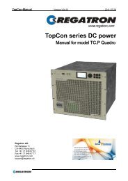
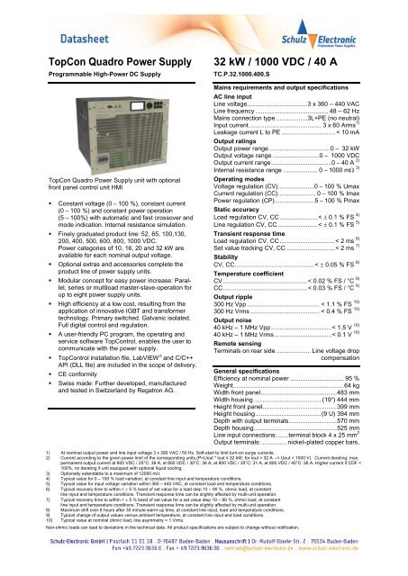
TopCon Quadro Power Supply<br />
Programmable High-Power DC Supply<br />
32 kW / 1000 VDC / 40 A<br />
TC.P.32.1000.400.S<br />
TopCon Quadro Power Supply unit with optional<br />
front panel control unit HMI<br />
• Constant voltage (0 – 100 %), constant current<br />
(0 – 100 %) <strong>and</strong> constant power operation<br />
(5 – 100%) with automatic <strong>and</strong> fast crossover <strong>and</strong><br />
mode indication. Internal resistance simulation.<br />
• Finely graduated product line: 52, 65, 100,130,<br />
200, 400, 500, 600, 800, 1000 VDC.<br />
Power categories of 10, 16, 20 <strong>and</strong> 32 kW are<br />
available for each nominal <strong>output</strong> voltage.<br />
• Optional extras <strong>and</strong> accessories complete the<br />
product line of power supply units.<br />
• Modular concept for easy power increase: Parallel,<br />
series or multiload master-slave-operation for<br />
up to eight power supply units.<br />
• High efficiency at a low cost, resulting from the<br />
application of innovative IGBT <strong>and</strong> transformer<br />
technology. Primary switched. Galvanic isolated.<br />
Full digital control <strong>and</strong> regulation.<br />
• A user-friendly PC program, the operating <strong>and</strong><br />
service software TopControl, enables the user to<br />
communicate with the power supply.<br />
• TopControl installation file, LabVIEW ® <strong>and</strong> C/C++<br />
API (DLL file) are included in the scope of delivery.<br />
• CE conformity<br />
• Swiss made: Further developed, manufactured<br />
<strong>and</strong> tested in Switzerl<strong>and</strong> by Regatron AG.<br />
<strong>Mains</strong> <strong>requirements</strong> <strong>and</strong> <strong>output</strong> <strong>specifications</strong><br />
AC line input<br />
Line voltage................................... 3 x 360 – 440 VAC<br />
Line frequency .......................................... 48 – 62 Hz<br />
<strong>Mains</strong> connection type ..................3L+PE (no neutral)<br />
Input current .......................................... 3 x 60 Arms 1)<br />
Leakage current L to PE ............................... < 10 mA<br />
Output ratings<br />
Output power range ................................... 0 – 32 kW<br />
Output voltage range ...........................0 – 1000 VDC<br />
Output current range ...................................0 – 40 A 2)<br />
Internal resistance range .................... 0 – 1000 mΩ 3)<br />
Operating modes<br />
Voltage regulation (CV).....................0 – 100 % Umax<br />
Current regulation (CC)...................... 0 – 100 % Imax<br />
Power regulation (CP)....................... 5 – 100 % Pmax<br />
Static accuracy<br />
Load regulation CV, CC ...................... < ± 0.1 % FS 4)<br />
Line regulation CV, CC ....................... < ± 0.1 % FS 5)<br />
Transient response time<br />
Load regulation CV, CC ................................ < 2 ms 6)<br />
Set value tracking CV, CC ............................ < 2 ms 7)<br />
Stability<br />
CV, CC .............................................. < ± 0.05 % FS 8)<br />
Temperature coefficient<br />
CV ................................................. < 0.02 % FS / °C 9)<br />
CC ................................................. < 0.03 % FS / °C 9)<br />
Output ripple<br />
300 Hz Vpp .......................................... < 1.1 % FS 10)<br />
300 Hz Vrms ........................................ < 0.4 % FS 10)<br />
Output noise<br />
40 kHz – 1 MHz Vpp ................................... < 1.5 V 10)<br />
40 kHz – 1 MHz Vrms ................................. < 0.1 V 10)<br />
Remote sensing<br />
Terminals on rear side .................... Line voltage drop<br />
compensation<br />
General <strong>specifications</strong><br />
Efficiency at nominal power ............................... 95 %<br />
Weight ................................................................ 64 kg<br />
Width front panel ............................................ 483 mm<br />
Width housing ....................................... (19“) 444 mm<br />
Height front panel ........................................... 399 mm<br />
Height housing ...................................... (9 U) 394 mm<br />
Depth with <strong>output</strong> terminals............................ 570 mm<br />
Depth housing ................................................ 525 mm<br />
Line input connections: ...... terminal block 4 x 25 mm 2<br />
Output terminals: .............. nickel–plated copper bars,<br />
length: 40 mm, 1 hole 9 mm ∅ in each bar<br />
1) At nominal <strong>output</strong> power <strong>and</strong> line input voltage 3 x 390 VAC / 50 Hz. Soft-start to limit turn-on surge currents.<br />
2) Current according to the given power limit of the corresponding units.(P=Uout * Iout ≤ 32 kW; for Iout > 32 A --> Uout < 1000 V). Current derating: max.<br />
permanent <strong>output</strong> current at 800 VDC / 25°C: 39 A, at 800 VDC / 30°C: 36 A, at 800 VDC / 35°C: 31 A, at 800 VDC / 40°C: 26 A. Higher current if CDF <<br />
100%, no derating if unit equipped with optional liquid cooling.<br />
3) Optionally extendable to a maximum of 12000 mΩ<br />
4) Typical value for 0 – 100 % load variation, at constant line input <strong>and</strong> temperature conditions.<br />
5) Typical value for input voltage variation within 360 – 440 VAC, at constant load <strong>and</strong> temperature conditions.<br />
6) Typical recovery time to within < ± 5 % b<strong>and</strong> of set value for a load step 10 – 90 %, ohmic load, at constant<br />
line input <strong>and</strong> temperature conditions. Transient response time can be slightly affected by multi-unit operation.<br />
7) Typical recovery time to within < ± 5 % b<strong>and</strong> of set value for a set value step 10 – 90 %, ohmic load, at constant<br />
line input <strong>and</strong> temperature conditions. Transient response time can be slightly affected by multi-unit operation.<br />
8) Maximum drift over 8 hours after 30 minute warm-up time, at constant line input, load <strong>and</strong> temperature conditions.<br />
9) Typical change of <strong>output</strong> values versus ambient temperature, at constant line input <strong>and</strong> load conditions.<br />
10) Typical value at nominal ohmic load, line asymmetry < 1 Vrms.<br />
Non-ohmic loads can lead to deviations in the technical data. All product <strong>specifications</strong> are subject to change without notification.
TC.P.32.1000.400.S (continued)<br />
Ambient conditions<br />
Operating temperature ............................. 5 – 40°C 11)<br />
Storage temperature .................................. -25 – 70°C<br />
Relative air humidity (non-condensing) ........ 0 – 95 %<br />
Cooling<br />
St<strong>and</strong>ard: internal temperature-controlled fans<br />
Optional: integrated liquid cooling of the power stage,<br />
heat exchanger material: AC100 (Al-Ti-alloy),<br />
inlet / outlet on rear side, size: G 1/2"<br />
Protection<br />
Built-in protection<br />
Overvoltage protection<br />
(programmable)................................ 0 – 110 % Umax<br />
Overcurrent protection<br />
(programmable).................................0 – 110 % Imax<br />
Max. reactive load voltage ................... ≤ 110 % Umax<br />
Short circuit protection ....... Cont. short circuit allowed<br />
Internal diagnostics: line input conditions, transformer<br />
primary current, temperature conditions,<br />
processor idle time, system configuration, system<br />
communication, sensor signals, power semiconductors<br />
Type of protection (IEC 60529)<br />
Basic construction ....................IP 20 (current bars on<br />
rear side excluded)<br />
Mounted in cabinet .................................. Up to IP 53<br />
Conformity CE-Marking<br />
EMC Directive<br />
EMC emission ...................................... EN 61000-6-4<br />
EMC immunity ...................................... EN 61000-6-2<br />
Low Voltage Directive<br />
<strong>Electronic</strong> equipment<br />
for use in power installations ...................... EN 50178<br />
Isolation<br />
Line to <strong>output</strong> ............................................. 4000 Vrms<br />
Line to case ............................................... 2500 Vrms<br />
Output to case ........................... > 10 MΩ / 2 x 6.8 nF<br />
- bar 16) ................... + 1000 VDC / - 1000 VDC<br />
+ bar 16) .................. + 1000 VDC / - 1000 VDC<br />
St<strong>and</strong>ard programming interfaces<br />
Control port<br />
Isolation to electronics <strong>and</strong> earth: 125 Vrms<br />
25 pin D-sub connector, female, on rear panel<br />
Control port input functions<br />
Output voltage on / off ....................... 0 / 24 VAC / DC<br />
2 digital application inputs ............ 0 / 24 VAC / DC 12)<br />
Interlock circuit ...........................................0 / 24 VDC<br />
Voltage setting 0 – 100 %.............................. 0 – 10 V<br />
Current setting 0 – 100 % ............................... 0 – 0 V<br />
Power setting 0 – 100 %................................ 10 – 0 V<br />
Int. resistance setting 0 – 1000 mΩ 3) ............ 0 – 10 V<br />
Control port <strong>output</strong> functions<br />
Unit ready / error ................................... Relay contact<br />
Output voltage on ................................. Relay contact<br />
Temperature warning ........................... Relay contact<br />
Actual voltage readback 0 – 100 %................ 0 – 10 V<br />
Actual current readback 0 – 100 %................ 0 – 10 V<br />
Resolution (programming<br />
<strong>and</strong> readback): U, I, P, Ri ............................ 0.2 % FS<br />
St<strong>and</strong>ard programming interfaces (continued)<br />
RS232<br />
9 pin D-sub connector, female, on front panel<br />
Isolation to electronics <strong>and</strong> earth ............... 125 Vrms<br />
Baud rate ................................................. 38400 baud<br />
Resolution (programming <strong>and</strong> readback):<br />
U, I ........................................................... 0.025 % FS<br />
P, Ri ............................................................. 0.1 % FS<br />
Ordering Information<br />
Ordering code<br />
TC.P.32.1000.400.S(.Option)<br />
St<strong>and</strong>ard Scope of delivery<br />
TopCon power supply unit ready to install, including:<br />
...................... Operating manual (English or German)<br />
..................................................... RS232 cable 1.8 m<br />
........................................Installation disc TopControl,<br />
...........................LabVIEW ® <strong>and</strong> C/C++ API (DLL file)<br />
Options<br />
Front panel control unit HMI<br />
Integrated control, programming <strong>and</strong> display unit with<br />
graphic LC-Display, select wheel, push buttons <strong>and</strong><br />
interactive text menus<br />
Languages (switchable) ................... English, German<br />
Display resolution:<br />
U ..................................................................... 4 digits<br />
I ....................................................................... 3 digits<br />
P ......................................... Kilowatt + 1 decimal digit<br />
Ri ....................................................................... 1 mΩ<br />
Remote control unit RCU<br />
Specifications same as HMI, available in 2 versions:<br />
....................................... desk top <strong>and</strong> 19“ rackmount<br />
max. cable length ................................................ 40 m<br />
Desk top W x H x D .................... 355 x 100 x 290 mm<br />
19“ rackmount W x H x D .. 483 x 133 (3 U) x 290 mm<br />
Further options<br />
TFEAAPControl ............. Function Generating Engine<br />
Time-based <strong>and</strong> Parametric Pr.<br />
SASControl ........................ SAS Application Program<br />
including TFEAAP<br />
AccuControl ................... Battery Application Program<br />
RS232REAR 13) ....... RS232 On Front <strong>and</strong> Rear Panel<br />
USB 14) ...........................Interface USB on Rear Panel<br />
RS422 13) ................................. RS422 on Rear Panel<br />
ETHERNET 15) ...............Ethernet to RS232 Converter<br />
............................................... External converter unit,<br />
IEEE 14) ......... GPIB/ IEEE488.2/ SCPI on Rear Panel<br />
................................................... cannot be combined<br />
..................................... with CANOPEN nor with USB<br />
CANOPEN 14) ............ CAN/ CANOPEN on Rear Panel<br />
PROFIBUS 15) ... Profibus DP 485 to RS232 Converter<br />
................................................................ external unit<br />
CANCABLE .................................... Connecting Cable<br />
................ for Multi-Unit Operation or RCU: 2, 5, 10 m<br />
PACOB ............ Protection against Accidental contact<br />
IRXTS 3) .............. Internal resistance range extension<br />
LCAL ................ Integrated liquid cooling of the power<br />
stage, inlet / outlet on rear side, size G 1/2"<br />
AIRFILTER .................. Front Panel Airfilter 6 U / 9 U<br />
ISR ........................................ Integrated Safety Relay<br />
NSOV ....... Non-St<strong>and</strong>ard Output Voltage (if possible)<br />
11) Ambient temperature or CDF restrictions: refer to <strong>output</strong> ratings.<br />
12) Customer-specificly programmable.<br />
13) This option <strong>and</strong> RS232: time-shared mode required, if used together.<br />
14) RS232 only on Rear Panel.<br />
15) Please order option RS232REAR separately.<br />
16) Peak Voltage including DC-Output Voltage.