ptac control board kit rskp0006 installation instructions - Amana PTAC
ptac control board kit rskp0006 installation instructions - Amana PTAC
ptac control board kit rskp0006 installation instructions - Amana PTAC

Create successful ePaper yourself
Turn your PDF publications into a flip-book with our unique Google optimized e-Paper software.
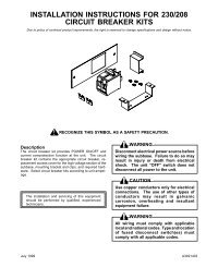
<strong>PTAC</strong> CONTROL BOARD KIT<br />
RSKP0006<br />
INSTALLATION INSTRUCTIONS<br />
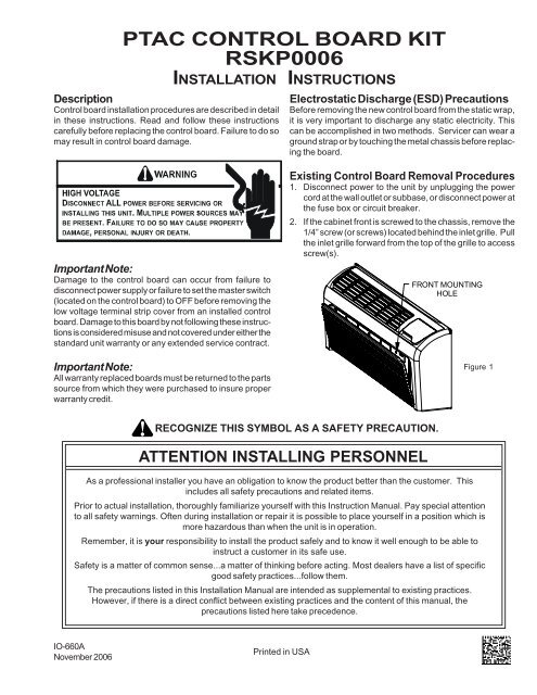
Description<br />
Control <strong>board</strong> <strong>installation</strong> procedures are described in detail<br />
in these <strong>instructions</strong>. Read and follow these <strong>instructions</strong><br />
carefully before replacing the <strong>control</strong> <strong>board</strong>. Failure to do so<br />
may result in <strong>control</strong> <strong>board</strong> damage.<br />
Electrostatic Discharge (ESD) Precautions<br />
Before removing the new <strong>control</strong> <strong>board</strong> from the static wrap,<br />
it is very important to discharge any static electricity. This<br />
can be accomplished in two methods. Servicer can wear a<br />
ground strap or by touching the metal chassis before replacing<br />
the <strong>board</strong>.<br />
Important Note:<br />
Damage to the <strong>control</strong> <strong>board</strong> can occur from failure to<br />
disconnect power supply or failure to set the master switch<br />
(located on the <strong>control</strong> <strong>board</strong>) to OFF before removing the<br />
low voltage terminal strip cover from an installed <strong>control</strong><br />
<strong>board</strong>. Damage to this <strong>board</strong> by not following these <strong>instructions</strong><br />
is considered misuse and not covered under either the<br />
standard unit warranty or any extended service contract.<br />
Important Note:<br />
All warranty replaced <strong>board</strong>s must be returned to the parts<br />
source from which they were purchased to insure proper<br />
warranty credit.<br />
Existing Control Board Removal Procedures<br />
1. Disconnect power to the unit by unplugging the power<br />
cord at the wall outlet or subbase, or disconnect power at<br />
the fuse box or circuit breaker.<br />
2. If the cabinet front is screwed to the chassis, remove the<br />
1/4” screw (or screws) located behind the inlet grille. Pull<br />
the inlet grille forward from the top of the grille to access<br />
screw(s).<br />
FRONT MOUNTING<br />
HOLE<br />
Figure 1<br />
RECOGNIZE THIS SYMBOL AS A SAFETY PRECAUTION.<br />
ATTENTION INSTALLING PERSONNEL<br />
As a professional installer you have an obligation to know the product better than the customer. This<br />
includes all safety precautions and related items.<br />
Prior to actual <strong>installation</strong>, thoroughly familiarize yourself with this Instruction Manual. Pay special attention<br />
to all safety warnings. Often during <strong>installation</strong> or repair it is possible to place yourself in a position which is<br />
more hazardous than when the unit is in operation.<br />
Remember, it is your responsibility to install the product safely and to know it well enough to be able to<br />
instruct a customer in its safe use.<br />
Safety is a matter of common sense...a matter of thinking before acting. Most dealers have a list of specific<br />
good safety practices...follow them.<br />
The precautions listed in this Installation Manual are intended as supplemental to existing practices.<br />
However, if there is a direct conflict between existing practices and the content of this manual, the<br />
precautions listed here take precedence.<br />
IO-660A<br />
November 2006<br />
Printed in USA
ON<br />
1 2 3<br />
LOAD<br />
COM<br />
265<br />
230<br />
3. Remove cabinet front from chassis by tilting the bottom of<br />
the front forward, lifting slightly up and forward.<br />
4. If a remote thermostat or any low voltage accessory is<br />
being used, remove the low voltage pin connector from the<br />
low voltage terminal strip. If a previous version <strong>board</strong> is<br />
being replaced remove wires from the low voltage terminal<br />
strip.<br />
PULL TO REMOVE<br />
THERMOSTAT KNOB<br />
PULL TO REMOVE<br />
MODE SWITCH KNOB<br />
Lift Off<br />
ESCUTCHEON<br />
SCREW (2)<br />
SCREW<br />
12. The external transformer will come with the Black 37<br />
wires connected to the LOAD terminal of the transformer<br />
(LOAD terminals are the low voltage terminals) and the<br />
Grey 22 wire connected to the COM terminal on the<br />
transformer. The Grey 21 wire will need to be connected<br />
to the 230 or 265 volt tap on the transformer. Place the<br />
<strong>control</strong> panel back on its hinges.<br />
NOTE: Refer to the serial plate for voltage information.<br />
13. Install the new <strong>board</strong> and reinstall the screws removed in<br />
step # 8.<br />
14. Using the insulated terminals connect the two (2) Black<br />
37 wires from the Load terminals on the transformer to the<br />
“24VAC Transformer” terminals on the <strong>control</strong> <strong>board</strong>. See<br />
Figure 4.<br />
15.Connect Grey 22 wire from the COM terminal on the<br />
transformer to line 2 on the <strong>control</strong> <strong>board</strong>. Connect Grey<br />
21 wire from the transformer to line 1 on the <strong>control</strong> <strong>board</strong>.<br />
TRANSFORMER<br />
Figure 2<br />
5. Remove knobs and escutcheon.<br />
6. Remove the two mounting screws, one on each side of<br />
<strong>control</strong> <strong>board</strong> cover. Some models may have a screw on<br />
the lower right side of the <strong>control</strong> panel that will need to be<br />
removed. Tilt <strong>control</strong> panel out and remove cover.<br />
7. Remove the wires from the <strong>board</strong> in the unit, including<br />
Thermistor Sensors if they plug into the <strong>board</strong>.<br />
8. Remove the four screws holding the <strong>board</strong> and remove the<br />
old <strong>board</strong>.<br />
Figure 3<br />
New Control Board Installation Procedures<br />
TRANSFORMER<br />
LINE<br />
BK37<br />
GY22<br />
GY21<br />
BK37<br />
LINE 1 HEATER 1 HEATER 2 LINE 2 COMPRESSOR<br />
9. If existing unit has a remote mounted “off <strong>board</strong>” transformer<br />
for <strong>board</strong> power, proceed to Step 13.<br />
10. Lift the <strong>control</strong> panel up so the <strong>control</strong> panel is free of its<br />
hinges. Orient the <strong>control</strong> panel so there is easy access<br />
for mounting components to the inside of the <strong>control</strong><br />
panel.<br />
11. Using the two #8 screws that are provided, screw the<br />
transformer that was provided with the <strong>kit</strong> to the <strong>control</strong><br />
panel in the transformer mounting holes provided in the<br />
panel. See Figure 3.<br />
2<br />
24VAC~TRANSFORMER<br />
12VA CLASS 2 ONLY<br />
Figure 4
16. Thermistor Temperature Sensors Installation<br />
A. It is recommended that the Indoor Discharge Thermistor<br />
(with the YELLOW wires) be installed but it is<br />
optional. If you chose not to install this sensor, the<br />
green status light will remain illuminated continuously.<br />
For status light functionality, the YELLOW<br />
thermistor MUST be installed. Instructions are as<br />
follows:<br />
A1. Carefully cut and remove the gasket on the left and<br />
right sides of discharge screen. Remove the two (2)<br />
5/16” screws holding the indoor exhaust screen above<br />
the indoor coil. Remove the indoor exhaust screen.<br />
Remove the two (2) 1/4” screws connecting the heater<br />
panel to the evaporator coil.<br />
Remove the two (2) screws mounting the air baffle to<br />
the top of the heater panel and remove and discard the<br />
air baffle.<br />
A2. Install the new air baffle. Route the yellow thermistor<br />
probe from right to left through the wiring tube enclosure.<br />
Mount the black tip of the yellow thermistor<br />
probe in the plastic clip provided. Hold the plastic<br />
clamp in place and secure the clamp to the left end of<br />
heater panel using one of the original screws. Replace<br />
the screw on the right end of the air baffle being<br />
careful not to damage the wiring insulation on the<br />
probe.<br />
A3. Replace the heater panel, routing the yellow wire<br />
around the right end of the heater panel and into the<br />
<strong>control</strong> panel pulling snug to prevent the wire from<br />
being entangled in the blower wheel or being visible<br />
from above. Replace the two screws mounting the<br />
heater panel to the evaporator coil.<br />
A4. Replace the exhaust grille and two mounting screws.<br />
A5. Connect the yellow wire using the plug-on connector<br />
to the new <strong>board</strong> on the IDT (yellow) terminals.<br />
B. If the existing Indoor Ambient Thermistor (with the<br />
BLACK wires) was connected to the <strong>board</strong> by a plugon<br />
connector, reconnect it to the new <strong>board</strong> on the IAT<br />
(black) terminals. If the existing Indoor Coil Thermistor<br />
was soldered to the previous <strong>board</strong>, install the<br />
new black thermistor per Figure 6 and connect as<br />
above.<br />
Clip is designed to be pushed<br />
into the coil between<br />
the aluminum fins<br />
and attach over<br />
two (2) screws.<br />
CLAMP END OF<br />
THERMISTOR<br />
SECURELY<br />
PLASTIC CLAMP<br />
WIRE ENCLOSURE<br />
ROUTE THERMISTOR<br />
THROUGH TUBE ON<br />
BLOWER EXTENSION<br />
YELLOW<br />
THERMISTOR<br />
Figure 6<br />
Figure 5<br />
3
C. If the existing Indoor Coil Thermistor (with the RED<br />
wires) was connected to the <strong>board</strong> by a plug-on<br />
connector, reconnect it to the new <strong>board</strong> on the ICT<br />
(red) terminals. If the previous <strong>board</strong> used indoor coil<br />
bi-metals, remove and discard the bi-metal devices.<br />
The access door will need to be removed on the indoor<br />
coil to gain access to the bi-metal. See Figure 6. The<br />
Indoor Coil Thermistor will need to clip on the vertical<br />
section of the 90-degree bend of the inlet line to the<br />
indoor coil. See Figure 7. Connect the Indoor Coil<br />
Thermistor to the <strong>board</strong> as noted above.<br />
D. If the existing Outdoor Coil Thermistor (with the<br />
BLUE wires) was connected to the <strong>board</strong> by a plugon<br />
connector, reconnect it to the new <strong>board</strong> on the<br />
OCT (blue) terminals. If the previous <strong>board</strong> used<br />
indoor coil bi-metals, remove and discard the bi-metal<br />
devices. The Indoor Coil Thermistor will need to clip on<br />
the crossover tube shown in Figure 8. There will be<br />
two clips supplied in the <strong>kit</strong> for the Blue Thermistor.<br />
One clip as supplied on the sensor will fit 5/16” tubing<br />
used on the bent coil, and an additional clip (loose in<br />
the bag) will fit 3/8” tubing used on the flat slab coil.<br />
If you have a slab coil, you will need to remove the 5/16”<br />
clip from the sensor and replace it with the 3/8” tube<br />
clip. Connect the Outdoor Coil Thermistor to the <strong>board</strong><br />
as noted above. Outdoor Coil Thermistors are only<br />
used on Heat Pump models; DO NOT INSTALL THIS<br />
SENSOR IF THE UNIT IS NOT A HEAT PUMP.<br />
Figure 8<br />
Cross over tube<br />
for 9,12 and 15k<br />
or center tube for<br />
7,000 BTU<br />
17. If the unit has a condensate pump, go to step 18. If the unit<br />
has a power vent or power door, go to step 19. Otherwise<br />
proceed with step 20. Refer to wiring diagrams in back of<br />
manual.<br />
18. Condensate Pump Units Only<br />
(See Wiring Diagram Page 10<br />
Reconnect the wires across the top terminals of the<br />
<strong>control</strong> <strong>board</strong>. Connect as follows:<br />
Red 33 to Line 1<br />
Brown 34 to Heater 1<br />
Brown 34 to Heater 2<br />
Power cord (or black 18) to Line 2<br />
Violet 12 and Yellow 3 to Compressor<br />
Black 16 to Fan High<br />
Red 17 to Fan Low<br />
19 from reversing valve and Yellow 1 to Rev. Valve.<br />
Connect the yellow 5 wire to the 230 or 265-volt terminal<br />
as applicable using the piggyback terminal on the yellow<br />
5 wire. Go to step 21.<br />
Figure 7<br />
INDOOR COIL THERMISTOR - RED<br />
All Units<br />
Connect to ICT on Control Board<br />
4
19. Power Vent/Power Door Units Only<br />
(See Wiring Diagram Page 9)<br />
Reconnect the wires across the top terminals of the<br />
<strong>control</strong> <strong>board</strong>. Connect as follows:<br />
Red 33 to Line 1<br />
Brown 34 to heater 1<br />
Brown 34 to Heater 2<br />
Power cord (or black 18) to Line 2<br />
Violet 12 to Compressor<br />
Blue 4 to Fan high<br />
Blue 15 and Blue 10 to Fan Low<br />
19 from reversing valve to Rev. Valve<br />
Connect the white 7 wire to the 230 or 265-volt terminal as<br />
applicable using the piggyback terminal on the white 7<br />
wire. Go to step 21.<br />
20. Reconnect the wires across the top terminals of the<br />
<strong>control</strong> <strong>board</strong>. Connect as follows:<br />
(See Wiring Diagram Page 8)<br />
Red 33 to line 1<br />
Brown 34 to heater 1<br />
Brown 34 to heater 2<br />
Power cord or black 18 to line 2<br />
Violet 12 to compressor<br />
Black 16 to Fan High<br />
Red 17 to Fan Low<br />
19 from reversing valve to Rev. Valve.<br />
21. If a remote wired thermostat and an additional REK01B<br />
escutcheon that states “THIS UNIT IS CONTROLLED BY<br />
WALL MOUNTED THERMOSTAT” is used, the knob and<br />
potentiometer will need to be removed. To remove the<br />
knob, loosen the set screw on the side of the knob with<br />
a flat screwdriver and pull knob from potentiometer shaft.<br />
To remove the potentiometer, loosen the nut with a 10mm<br />
driver and remove the nut and 2 washers. Pull the shaft<br />
free of the panel. Reassemble potentiometer, washers,<br />
nut and knob and store for future use. These will be<br />
required if the unit is ever converted back to local <strong>control</strong>s<br />
instead of wired thermostat operation.<br />
The <strong>control</strong> <strong>board</strong> cover is now ready to be installed. The<br />
ribbon for the touch pad will need to be connected to the<br />
<strong>control</strong> <strong>board</strong>. Take caution not to bend or fold the<br />
ribbon (See Figure 9 for ribbon connection).<br />
Install orange connector from the thermostat on the touch<br />
pad to the IHD Terminals on <strong>control</strong> <strong>board</strong>, unless the<br />
knob has been removed.<br />
Ensure that no wires are pinched or caught between the<br />
cover and the panel and then reinstall the screws removed<br />
in Step 5.<br />
22. If a remote thermostat or any low voltage accessory is<br />
being used connect the low voltage pin connector to low<br />
voltage terminal strip.<br />
If replacing a previous version <strong>board</strong> you will need to use<br />
the 18 pin connector supplied with the <strong>board</strong> for low<br />
voltage accessories. Wires supplied with this <strong>kit</strong> have<br />
terminal ends on the wires. Insert the terminal end into<br />
the correctly labeled slot, push in and it will lock in place.<br />
After loading pin connector use the wire nuts supplied<br />
with the <strong>kit</strong> to wire nut the new wires onto the existing<br />
wires supplied for low voltage accessories. See Figure 9<br />
on page 5.<br />
23. Set the master switch to ON. Restore electrical power<br />
and verify unit functionality.<br />
24. This <strong>control</strong> can be configured for several operational<br />
features.<br />
A. If the unit was being <strong>control</strong>led by a wired wall<br />
thermostat, the <strong>board</strong> will have to be configured to<br />
allow the thermostat to operate the unit. To configure<br />
for a wired wall thermostat, press and hold the FAN<br />
SPEED button and press the COOL button twice. The<br />
light in the bottom left hand corner below the OFF light<br />
will blink twice to confirm that the configuration was<br />
successful. Repeat step 24 if the light did not blink.<br />
B. If the unit will be <strong>control</strong>led by a wireless thermostat<br />
(Goodman DS01A using DT01A antenna on the unit),<br />
the <strong>board</strong> may have to be configured to allow the<br />
wireless thermostat to operate the unit. To configure<br />
for wireless operation, press and hold the FAN SPEED<br />
button and press the HEAT button twice. The light in<br />
the bottom left hand corner below the OFF light will<br />
blink twice to confirm that the configuration was<br />
successful. Repeat step 24 if the light did not blink.<br />
C. If constant fan is desired, the unit will need to be<br />
configured by pressing and holding the HEAT button<br />
and pressing the OFF button twice. To revert to auto/<br />
cyclic fan operation, press and hold the COOL button<br />
and press the OFF button twice.<br />
D. Other configuration items exist, but can only be<br />
accessed over the wireless antenna to a wireless site<br />
platform (Goodman DP01A).<br />
E. To reset all the configuration items back to the factory<br />
defaults, turn the master switch off for 10 seconds,<br />
and then hold the HEAT and COOL button while<br />
turning the master switch back on.<br />
25. Replace the front in reverse order as removed in Steps 2<br />
and 3.<br />
5
BROWN<br />
BLACK w/WHITE STRIPE<br />
YELLOW w/BLACK STRIPE<br />
RED<br />
GREEN<br />
WHITE<br />
YELLOW<br />
BLUE<br />
GREEN w/YELLOW STRIPE<br />
Remote Thermostat<br />
*Only load wires needed for accessories attached to unit.<br />
Figure 9<br />
6
REV.<br />
VALVE<br />
YELLOW<br />
FAN<br />
HIGH<br />
FAN<br />
LOW<br />
RIBBON CONNECTOR<br />
DSI IN GL B GH<br />
BLACK<br />
YELLOW<br />
ORANGE from Touch Pad<br />
BLUE<br />
Heat Pump models ONLY.<br />
Must not be used<br />
on PTC models.<br />
LINE 1<br />
RED<br />
24VAC-TRANSFORMER<br />
ON<br />
Left is ON<br />
Position<br />
Figure 10<br />
7
WIRING DIAGRAMS<br />
REMOTE THERMOSTAT OPERATION<br />
COOLING UNIT<br />
W/ELECTRIC HEAT<br />
CONNECT<br />
FUNCTION<br />
R TO:<br />
OFF<br />
-----<br />
HEAT PUMP W/AUXILIARY<br />
ELECTRIC HEAT<br />
CONNECT<br />
FUNCTION<br />
R TO:<br />
OFF<br />
-----<br />
1ST STAGE<br />
ANTICIPATOR<br />
CURRENT: .1<br />
2ND STAGE<br />
ANTICIPATOR<br />
CURRENT: .1<br />
WIRING DIAGRAM<br />
205180 REV.0<br />
FAN<br />
G<br />
FAN<br />
G<br />
COOL<br />
G, Y/W1<br />
COOL<br />
G, Y/W1<br />
HEAT<br />
*<br />
1ST STAGE<br />
HEAT<br />
2ND STAGE<br />
HEAT<br />
G,B,Y/W1<br />
G, W2<br />
* FOR A HEAT PUMP<br />
THERMOSTAT USED<br />
ON A STRAIGHT<br />
COOL UNIT<br />
H<br />
C<br />
F<br />
YL10<br />
OD<br />
FAN/COMP<br />
CAP<br />
RD13<br />
HIGH VOLTAGE!<br />
DISCONNECT ALL POWER BEFORE SERVICING OR INSTALLING THIS<br />
UNIT. MULTIPLE POWER SOURCES MAY BE PRESENT. FAILURE TO<br />
DO SO MAY CAUSE PROPERTY DAMAGE, PERSONAL INJURY OR DEATH.<br />
BK37<br />
BK37<br />
7<br />
TRANSFORMER<br />
230<br />
X3<br />
LOAD<br />
265<br />
24VAC~TRANSFORMER<br />
12VA CLASS 2 ONLY<br />
X1<br />
COM<br />
E11 E12<br />
RD33<br />
LINE 1<br />
E1<br />
GY21<br />
1<br />
ELECTRIC<br />
HEATER<br />
HEATER 1 HEATER 2<br />
RIBBED<br />
2 WIRE<br />
G<br />
N<br />
GY22<br />
LINE 2<br />
BK18<br />
S<br />
5<br />
C<br />
R<br />
FUSE<br />
COMPRESSOR<br />
BK16<br />
FAN<br />
HIGH<br />
BR14<br />
RD17<br />
FAN<br />
LOW<br />
20<br />
RE V<br />
VALVE<br />
SOLENOID<br />
E2 E3 E4 E5 E6 E7 E8 E9 E10<br />
K4 K5 K6<br />
CP4<br />
BR34<br />
BR34<br />
CR11<br />
P2<br />
COMP<br />
VT12<br />
P5<br />
WH15<br />
FAN<br />
MOTOR<br />
19<br />
REV<br />
VALVE<br />
K1 K2 K3<br />
P1<br />
P4<br />
X4<br />
IDT<br />
YELLOW<br />
GREEN<br />
3<br />
X2<br />
P9<br />
ICT<br />
RED<br />
P8<br />
OCT<br />
BLUE<br />
ORANGE<br />
SW2<br />
P10<br />
P11<br />
P13<br />
M1<br />
ON / OFF<br />
MASTER SWITCH<br />
COM A<br />
COM B<br />
DS1 DS2 MS1 MS2 EH IN LS FD1 FD2 TF- TF+ C R GL W2 Y/W1 B GH<br />
AUXILIARY<br />
REMOTE THERMOSTATE<br />
IAT<br />
BLACK<br />
M2<br />
6<br />
NOTES:<br />
1<br />
WARNING: DISCONNECT POWER BEFORE SERVICING. W IRING<br />
TO UNIT MUST BE PROPERLY POLARIZED (FOR 265V) AND GROUNDED.<br />
2<br />
RIBBED WIRE MUST BE CONNECTED AS SHOWN<br />
3 ON HEAT PUMP MODELS ONLY.<br />
4 ON UNITS W ITH FRONT DESK CONTROL SWITCH.<br />
5 BK18 ON LINE 2 WITH FUSE SHOWN CONNECTED FOR 265V. FOR 230V & 11<br />
5 V, CONNECT<br />
POWER CORD TO LINE 2.<br />
6 FOR REMOTE OPERATION, SEE CONFIGURATION CHART.<br />
4<br />
FRON T<br />
DESK<br />
SWITCH<br />
USE COPPER<br />
CONDUCTORS ONLY<br />
GN<br />
CHASSIS<br />
1 CONTRO L<br />
PANEL<br />
WIRE LEGEND<br />
7 IF SUPPLY VOLTAGE IS 208V/230V USE THE 230V TAP ON TRAN SFORMER.<br />
IF SUPPLY VOLTA GE IS 265V USE THE 265V TAP ON TRANSFORMER.<br />
115V TRANSFORMER NOT SHOWN.<br />
HIGH VOLTAGE<br />
(FACTORY)<br />
HIGH VOLTAGE<br />
(FACTORY OR FIELD)<br />
8 FOR CONTINUOS FAN OPERATION SEE CONFIGURATION CHART.<br />
LOW VOLTAGE<br />
(FACTORY OR FIELD)<br />
8
265<br />
230<br />
WIRING DIAGRAMS<br />
REMOTE THERMOSTAT OPERATION<br />
FUNCTION<br />
CONNECT CONNECT<br />
R TO:<br />
FUNCTION<br />
R TO:<br />
OFF ----- OFF<br />
-----<br />
FAN<br />
COOL<br />
HEAT<br />
COOLING UNIT<br />
W/ELECTRIC HEAT<br />
G**<br />
G, Y/W1<br />
*<br />
HEAT PUMP W/AUXILIARY<br />
ELECTRIC HEAT<br />
FAN<br />
COOL<br />
1ST STAGE<br />
HEAT<br />
2ND STAGE<br />
HEAT<br />
G**<br />
G, Y/W1<br />
G,B,Y/W1<br />
G, W2<br />
1ST STAGE<br />
ANTICIPATOR<br />
CURRENT: .1<br />
2ND STAGE<br />
ANTICIPATOR<br />
CURRENT: .1<br />
* FOR A HEAT PUMP<br />
THERMOSTAT USED<br />
ON A STRAIGHT<br />
COOL UNIT<br />
** GL- low speed<br />
GH- high speed<br />
H C F<br />
6<br />
POWER<br />
VE N T<br />
MOTOR<br />
VENT<br />
MUFFIN<br />
FAN<br />
LINE<br />
COM<br />
208<br />
240<br />
WIRING DIAGRAM<br />
20518101 REV 0<br />
POWER<br />
HIGH VOLTAGE!<br />
DISCONNECT ALL POWER BEFORE SERVICING OR INSTALLING THIS<br />
UNIT. MULTIPLE POWER SOURCES MAY BE PRESENT. FAILURE TO<br />
DO SO MAY CAUSE PROPERTY DAMAGE, PERSONAL INJURY OR DEATH.<br />
BK37<br />
BK37<br />
LINE<br />
COM<br />
X3<br />
24VAC~TRANSFORMER<br />
12VA CLASS 2 ONLY<br />
8<br />
X1<br />
E11 E12<br />
RD33<br />
LINE 1<br />
E1<br />
1<br />
GY21<br />
RIBBED<br />
2 WIRE<br />
GN<br />
ELECTRIC<br />
HEATER<br />
HEATER 1 HEATER 2<br />
YL10<br />
GY22<br />
RD13<br />
COMP<br />
S<br />
R<br />
C<br />
BK18<br />
LINE 2<br />
5<br />
VT12<br />
OD<br />
FAN/COMP<br />
CAP<br />
WH15<br />
BK16<br />
TERMINAL<br />
BLOCK<br />
BR14<br />
RD17<br />
RD14<br />
(PV)<br />
BK17<br />
(PV)<br />
BU4<br />
(PV)<br />
WH7<br />
(PV)<br />
E2 E3 E4 E5 E6 E7 E8 E9 E10<br />
K4 K5 K6<br />
CP4<br />
BR34<br />
BR34<br />
CR11<br />
P2<br />
COMPRESSOR<br />
P5<br />
FAN<br />
MOTOR<br />
FAN<br />
HIGH<br />
FAN<br />
LOW<br />
REV<br />
VALVE<br />
K1 K2 K3<br />
P1<br />
P4<br />
1<br />
4<br />
7<br />
A<br />
WH8<br />
(PV)<br />
X4<br />
IDT<br />
YELLOW<br />
BK11<br />
(PV)<br />
GREEN<br />
ORANGE<br />
2<br />
5<br />
8<br />
BU15<br />
(PV)<br />
X2<br />
3<br />
6<br />
9<br />
B<br />
BK12<br />
(PV)<br />
BU2<br />
(PV)<br />
2<br />
BU9<br />
(PV)<br />
3<br />
1<br />
ON/OFF<br />
SWITCH<br />
BU10<br />
(PV)<br />
3<br />
REV<br />
20<br />
VALVE<br />
SOLENOID<br />
19<br />
P9<br />
ICT<br />
RED<br />
P8<br />
OCT<br />
BLUE<br />
SW2<br />
P10<br />
P11<br />
P13<br />
M1<br />
ON / OFF<br />
MASTER SWITCH<br />
COM A<br />
COM B<br />
DS1 DS2 MS1 MS2 EH IN LS FD1 FD2 TF- TF+ C R GL W2 Y/W1 B GH<br />
AUXILIARY<br />
REMOTE THERMOSTATE<br />
IAT<br />
BLACK<br />
M2<br />
7<br />
4<br />
FRON T<br />
DESK<br />
SWITCH<br />
NOTES :<br />
1 WARNING: DISCONNECT POWER BEFORE SERVICING. WIRING<br />
TO UNIT MUST BE PROPERLY POLARIZED (FOR 265V) AND GROUNDED.<br />
2 RIBBED WIRE MUST BE CONNECTED AS SHOWN.<br />
3 ON HEAT PUMP MODELS ONLY.<br />
4 ON UNITS WITH FRONT DESK CONTROL SWITCH.<br />
5 BK18 ON LINE 2 WITH FUSE SHOWN CONNECTED FOR 265V. FOR 230V AND 115V, CONNECT<br />
POWER CORD TO LINE 2.<br />
6 IF SUPPLY VOLTAGE IS 208V MOVE 240V LEAD TO 208V TAP ON TRANSFORMER.<br />
265V AND 115V TRANSFORMER NOT SHOWN .<br />
7 FOR REMOTE OPERATION, SEE CONFIGARATION CHART.<br />
8 IF SUPPLY VOLTAGE IS 208V/230V USE THE 230V TAP ON TRANSFORMER.<br />
I F SUPPLY VOLTAGE IS 265V USE THE 265V TAP ON TRANSFORMER.<br />
1 15V TRANSFORMER NOT SHOWN.<br />
9FOR CONTINUOS FAN OPERATION SEE CONFIGURATION CHART.<br />
CHASSIS<br />
USE COPPER<br />
CONDUCTORS ONLY<br />
GN<br />
1<br />
WIRE LEGEND<br />
HIGH VOLTAGE<br />
(FACTORY)<br />
HIGH VOLTAGE<br />
(FACTORY OR FIELD)<br />
LOW VOLTAGE<br />
(FACTORY OR FIELD)<br />
CONTROL<br />
PANEL<br />
9
COM<br />
208<br />
240<br />
COM<br />
208<br />
240<br />
WIRING DIAGRAMS<br />
HEAT PUMP W/AUXILIARY<br />
ELECTRIC HEAT<br />
FUNCTION<br />
CONNECT CONNECT<br />
R TO:<br />
FUNCTION<br />
R TO:<br />
OFF ----- OFF<br />
-----<br />
FAN<br />
REMOTE THERMOSTAT OPERATION<br />
COOLING UNIT<br />
W/ELECTRIC HEAT<br />
G<br />
FAN<br />
G<br />
1ST STAGE<br />
ANTICIPATOR<br />
CURRENT: .1<br />
2ND STAGE<br />
ANTICIPATOR<br />
CURRENT: .1<br />
* FOR A HEAT PUMP<br />
THERMOSTAT USED<br />
ON A STRAIGHT<br />
COOL UNIT<br />
WIRING DIAGRAM<br />
205184 REV 0<br />
COOL<br />
G, Y/W1<br />
COOL<br />
G, Y/W1<br />
HEAT<br />
*<br />
1ST STAGE<br />
HEAT<br />
2ND STAGE<br />
HEAT<br />
G,B,Y/W1<br />
G, W2<br />
H<br />
C<br />
F<br />
YL10<br />
RD13<br />
OD<br />
FAN/COMP<br />
CAP<br />
BR14<br />
HIGH VOLTAGE!<br />
DISCONNECT ALL POWER BEFORE SERVICING OR INSTALLING THIS<br />
UNIT. MULTIPLE POWER SOURCES MAY BE PRESENT. FAILURE TO<br />
DO SO MAY CAUSE PROPERTY DAMAGE, PERSONAL INJURY OR DEATH.<br />
BK37<br />
BK37<br />
GY21<br />
X3<br />
24VAC~TRANSFORMER<br />
12VA CLASS 2 ONLY<br />
LINE<br />
X1<br />
E11 E12<br />
GY22<br />
8<br />
LINE 1<br />
E1<br />
RD33<br />
1<br />
BR34<br />
ELECTRIC<br />
HEATER<br />
RIBBED<br />
2 WIRE<br />
G<br />
N<br />
BR34<br />
HEATER 1 HEATER 2<br />
YL5<br />
(CP)<br />
LINE 2<br />
COMP<br />
S<br />
R<br />
C<br />
VT12<br />
WH15<br />
BK16<br />
FAN<br />
MOTOR<br />
YL3<br />
(CP)<br />
RD17<br />
E2 E3 E4 E5 E6 E7 E8 E9 E10<br />
K4 K5 K6<br />
CP4<br />
CR11<br />
BK18<br />
P2<br />
5<br />
COMPRESSOR<br />
P5<br />
FAN<br />
HIGH<br />
FAN<br />
LOW<br />
REV<br />
VALVE<br />
K1 K2 K3<br />
P1<br />
P4<br />
1<br />
3<br />
5<br />
A<br />
YL1<br />
(CP)<br />
X4<br />
IDT<br />
YELLOW<br />
GREEN<br />
ORANGE<br />
OCT<br />
BLUE<br />
X2<br />
2<br />
4<br />
6<br />
B<br />
OR8<br />
(CP)<br />
6<br />
WH 6<br />
(CP)<br />
LINE<br />
20<br />
REV<br />
VALVE<br />
SOLENOID<br />
19<br />
3<br />
P9<br />
ICT<br />
RED<br />
P8<br />
SW2<br />
P10<br />
P11<br />
P13<br />
M1<br />
ON / OFF<br />
MASTER SWITCH<br />
COM A<br />
COM B<br />
DS1 DS2MS1MS2EH IN LS FD1FD2TF-TF+ C R GL W2 Y/W1 B GH<br />
AUXILIARY<br />
REMOTE THERMOSTATE<br />
IAT<br />
BLACK<br />
M2<br />
7<br />
4<br />
FRONT<br />
DESK<br />
SWITCH<br />
NOTES<br />
1<br />
WARNING: DISCONNECT POWER BEFORE SERVICING. WIRING<br />
TO UNIT MUST BE PROPERLY POLARIZED (FOR 265V) AND GROUNDED.<br />
2 RIBBED WIRE MUST BE CONNECTED AS SHOWN.<br />
3 ON HEAT PUMP MODELS ONLY.<br />
4 ON UNITS WITH FRONT DESK CONTROL SWITCH.<br />
5 BK18 ON LINE 2 WITH FUSE SHOWN CONNECTED FOR 265V. FOR 230V AND 115V, CONNECT<br />
POWER CORD TO LINE 2.<br />
6 IF SUPPLY VOLTAGE IS 208V MOVE 240V LEAD TO 208V TAP ON TRANSFORMER.<br />
265V AND 115V TRANSFORMER NOT SHOWN.<br />
7 FOR REMOTE OPERATION, SEE CONFIGURATION CHART.<br />
8 IF SUPPLY VOLTAGE IS 208V, MOVE 204V LEAD TO 208V TAP ON TRANSFORMER.<br />
265V AND 115V TRANSFORMER NOT SHOWN.<br />
9 FOR CONTINUOS FAN OPERATION SEE CONFIGURATION CHART.<br />
USE COPPER<br />
CONDUCTORS ONLY<br />
GN<br />
CHASSIS<br />
1<br />
CONTROL<br />
PANEL<br />
WIRE LEGEND<br />
HIGH VOLTAGE<br />
(FACTORY)<br />
HIGH VOLTAGE<br />
(FACTORY OR FIELD)<br />
LOW VOLTAGE<br />
(FACTORY OR FIELD)<br />
10
THIS PAGE LEFT INTENTIONALLY BLANK<br />
11
Quality Makes the Difference!<br />
All of our systems are designed and manufactured with the same high quality standards regardless of size or<br />
efficiency. We have designed these units to significantly reduce the most frequent causes of product failure.<br />
They are simple to service and forgiving to operate. We use quality materials and components. Finally, every<br />
unit is run tested before it leaves the factory. That’s why we know. . .There’s No Better Quality.<br />
Visit our website at www.amana-<strong>ptac</strong>.com for information on:<br />
• Products<br />
• Warranties<br />
• Customer Services<br />
• Parts<br />
• Contractor Programs and Training<br />
• Financing Options<br />
®<br />
is a trademark of Maytag Corporation and is used under<br />
license to Goodman Company, L.P. All rights reserved.<br />
Goodman Company, L.P.<br />
2550 North Loop West, Suite 400<br />
Houston, TX 77092<br />
© 2006 Goodman Company, L.P.<br />
12