Bulk Matters - UK P&I
Bulk Matters - UK P&I
Bulk Matters - UK P&I

You also want an ePaper? Increase the reach of your titles
YUMPU automatically turns print PDFs into web optimized ePapers that Google loves.
<strong>UK</strong> P&I CLUB<br />
<strong>Bulk</strong> matters<br />
A focus on some of the issues surrounding the<br />
carriage of bulk cargo in the P&I world<br />
<strong>UK</strong> P&I CLUB<br />
IS MANAGED<br />
BY THOMAS<br />
MILLER<br />
1
Hold cleaning –<br />
preparing a ship<br />
for grain<br />
Surveyors inspection/<br />
requirements<br />
Prior to loading grain, all ships are usually subject to a<br />
survey by an approved independent surveyor. The<br />
surveyor will require the vessels particulars and details<br />
of at least the last three cargoes carried. He will then<br />
inspect the holds for cleanliness and infestation, or the<br />
presence of any material which could lead to infestation.<br />
When the surveyor is satisfied with the condition of the<br />
hold, he will issue the ship with a certificate stating<br />
which holds are fit to load grain.<br />
Purpose:<br />
To ensure cargo holds are prepared to receive<br />
the next cargo.<br />
Large claims have arisen when cargo holds have not<br />
been cleaned sufficiently to prevent cargo contamination.<br />
The requirements for cleaning the holds are dependent<br />
upon the previous cargo carried, the next cargo to be<br />
carried, charterers’ requirements, the requirements of<br />
shippers and/or the authorities at the port of loading and<br />
the receivers.<br />
It is becoming common practice for receivers to have an<br />
inspector at the load port.<br />
General<br />
Regardless of the previous cargo, all holds should be<br />
thoroughly cleaned by sweeping, scraping and highpressure<br />
sea water washing to remove all previous cargo<br />
residues and any loose scale or paint, paying particular<br />
attention to any that may be trapped behind beams,<br />
ledges, pipe guards, or other fittings in the holds.<br />
Cargo hold: coal sticking and discharging salt<br />
If the ship has been carrying DRI (direct reduced iron),<br />
the dust created by this particular cargo during loading<br />
or discharging, will be carried to all areas of the ships<br />
structure and the reaction between iron, oxygen and<br />
salt will create an aggressive effect wherever the dust<br />
may settle. This is particularly noticeable on painted<br />
superstructures. (The IMO <strong>Bulk</strong> Cargo Code contains<br />
guidelines).<br />
Whenever salt water washing is used to clean hatches,<br />
the relevant holds should always be rinsed with fresh<br />
water to minimise the effects of corrosion and to<br />
prevent salt contamination of future cargoes. In this<br />
respect, arrangements should be made in good time to<br />
ensure sufficient fresh water is available for this<br />
operation.<br />
Before undertaking a fresh water rinse, the supply line<br />
(normally the deck fire main or similar) will need to be<br />
flushed through to remove any residual salt water.<br />
Accordingly, it is suggested that fresh water rinsing of<br />
the holds is left until the end of hold cleaning operations<br />
to minimise the amount of fresh water required.<br />
Grain preparation and safe<br />
carriage<br />
One of the most difficult hold cleaning tasks is to<br />
prepare a ship for a grain cargo after discharging a dirty<br />
or dusty cargo such as coal or iron ore, particularly if<br />
the last cargo has left ‘oily’ stains on the paintwork or<br />
other deposits stubbornly adhering to the steel<br />
surfaces. Greasy deposits which remain on the<br />
bulkheads will require a ‘degreasing chemical wash’<br />
and a fresh water rinse in order to pass a grain<br />
inspection. The degreasing chemical used should be<br />
environmentally acceptable for marine use, and safe to<br />
apply by ships staff, who have had no special training<br />
and do not require any specialised protective<br />
equipment. Product safety data sheets of the chemical<br />
should be read, understood and followed by all persons<br />
involved with the environmentally friendly degreasing<br />
chemical.<br />
To avoid taint problems, fresh paint should not to be<br />
used in the holds or under the hatch lids at anytime<br />
during the hold preparation, unless there is sufficient<br />
time for the paint to cure and be free of odour as per the<br />
3
manufacturer’s instructions. Most marine coatings<br />
require at least seven days for the paint to be fully cured<br />
and odour free. All paint used in the holds and underside<br />
of the hatchcovers should be certified grain compatible<br />
and a certificate confirming this should be available<br />
onboard. Freshly painted hatches or hatchcovers will<br />
normally result in instant failure during the grain<br />
inspection, unless the paint has had time to cure.<br />
After washing, depending on weather conditions,<br />
cargo dust may lightly contaminate the underside of the<br />
hatch lids; however, the dust particles can easily be<br />
removed at a later date using a high-pressure portable<br />
fresh water gun.<br />
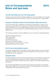
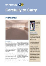
Example of portable high-pressure fresh water guns from Stromme<br />
Processed grains or grain cargoes that are highly<br />
susceptible to discolouration and taint should only be<br />
stowed in holds that have the paint covering intact. It is<br />
important that there is no bare steel, rust, scale, or any<br />
rust staining in the hold.<br />
Dependent upon the quality of the grain to be carried,<br />
the charterer may require the holds to be fumigated. This<br />
may be accomplished on passage with fumigant tablets<br />
introduced into the cargo on completion of loading.<br />
Fumigation can also be undertaken at the port of loading<br />
(or occasionally discharge). The ship will normally be<br />
advised how the fumigation is to be carried out and of<br />
any special precautions that will have to be taken.<br />
In all cases, the preparations (i.e. inspecting the holds<br />
and hatchcovers for gas-tight integrity) and fumigation<br />
must be carried out in accordance with the IMO<br />
document Recommendation on the Safe Use of<br />
Pesticides on Ships. Gas-detectors and proper personal<br />
protective equipment should be available and relevant<br />
ship’s officers should receive appropriate training in their<br />
use. After introduction of the fumigant, an appropriate<br />
period should be allowed (normally 12 hours) for the gas<br />
to build up sufficient pressure so that any leaks can be<br />
detected: the vessel must not depart from port before<br />
this period has expired. The entire process should be<br />
certified by a qualified fumigator. The holds must not be<br />
ventilated until the minimum fumigation period has<br />
expired, and care must be taken to ensure that<br />
subsequent ventilation does not endanger the crew.<br />
Ballast hold<br />
If the ship has a ballast hold, this should be discharged<br />
as soon as possible during the discharge sequence.<br />
This will allow ships staff the time to remove all cargo<br />
debris and prepare the hold for ballasting.<br />
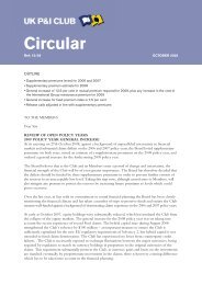
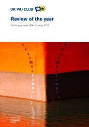
Illustrated, from top: Hatchcover underside; clean hatch rubber;<br />
hatch undersides and rubber packing<br />
Alongside the discharge port<br />
On non-working hatches, remove all cargo remnants,<br />
loose scale and flaking paint from the underside of the<br />
hatch lids and from all steelwork within the hold,<br />
provided safe access can be obtained. Then<br />
commence washing the underside of the hatchcovers<br />
using liquid soap (such as teepol), followed by a fresh<br />
water rinse with a high-pressure water gun.<br />
The hatch rubber seals should also be washed to<br />
remove cargo grime. However, caution is required to<br />
ensure that the hatch rubber seals are not damaged by<br />
the high pressure from the fresh water gun.<br />
4
Shore bulldozer/cocoa beans and shore personnel cleaning holds<br />
do not have an approved automatic means of<br />
preventing water ingress into the hold.<br />
If time permits, when the cargo has been discharged<br />
from respective hatches, all inner hatch coamings’<br />
should be teepol washed and fresh water rinsed with<br />
the fresh water high-pressure gun because it is more<br />
convenient to wash this area in port rather than at sea.<br />
If permitted by the port authority, all hatch tops should<br />
be dock water washed, ensuring that cargo remains are<br />
retained onboard and not washed into the dock. The<br />
fitting of plugs to all deck scuppers should help prevent<br />
any pollution claims alongside.<br />
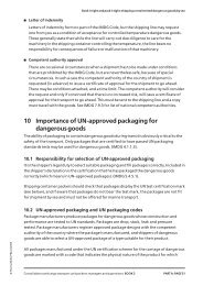
Illustrated, from top: Discharging soya meal; tapioca cargo sticking<br />
and; cargo hold after discharging minerals<br />
A good working relationship with the stevedores will<br />
probably assist the removal of cargo remains from all of<br />
the holds using the shore crane or other cargo-handling<br />
facilities, which will avoid lengthy difficulties for ships<br />
staff during the ballast voyage.<br />
The bilges and strums of the ballast hold should be<br />
thoroughly cleaned and all traces of previous cargo<br />
removed. The bilge suctions should be tested and<br />
confirmed as clear prior to any washing out of the cargo<br />
holds and the bilge spaces pumped out and secured<br />
with the bilge blanks.<br />
To prevent ballast water ingress into the bilge area, it is<br />
essential that the rubber joint/gasket is in good<br />
condition and all the bilge-blank securing bolts are fitted<br />
tightly. The un-seamanlike practice of securing the bilge<br />
blank with four bolts is unacceptable and may result in<br />
pressurising the bilge line. This must be avoided.<br />
Hatchcovers<br />
Prior to closing the hatchcovers, all the hatch trackways<br />
should be swept clean, then carefully hosed<br />
down. If a compressed air gun is used, it should be<br />
used with caution and suitable safety equipment should<br />
be worn to ensure both face and body protection.<br />
All hatch corner drains, including the non return valves,<br />
should be proven clean and clear. The blanking caps on<br />
the hatch corner drains, used to ensure hold airtightness<br />
should be attached by a chain to the drain.<br />
These blanking caps or plugs are provided if the drains<br />
5
Scupper plug fitted<br />
after clearing the port of discharge, mindful of pollution<br />
from the cargo remains.<br />
Prior to the commencement of the hold-cleaning, a<br />
quick safety pre-brief meeting should take place, which<br />
should include all the personnel who will be involved in<br />
the hold cleaning. During the pre-brief the hold-cleaning<br />
schedule should be discussed and the equipment and<br />
chemicals to be used must be fully explained and the<br />
safety data sheets understood by all involved. Basic<br />
safety routines should be established and the wearing<br />
of suitable attire throughout the hold cleaning must be<br />
of paramount importance.<br />
It is essential that permission is given by the port<br />
authority for this washing operation.<br />
Coaming/trackway covered in fertiliser; below, ship’s main deck<br />
covered by previous cargo<br />
Under normal circumstances, when it rains during<br />
cargo operations, discoloured water from the decks will<br />
flow into the dock and this is normally accepted by the<br />
port authority. The washing of cargo debris into the<br />
dock is not acceptable.<br />
In some loading ports, where helicopter operations are<br />
used for embarking and disembarking the pilot, it is a<br />
normal requirement of the port to wash down the<br />
helicopter area and at least one hatch length either side<br />
of the helicopter area, always ensuring that cargo<br />
debris is not washed into the dock.<br />
Preparation at sea<br />
To prevent cargo debris from the main deck being<br />
walked into the accommodation and tramped into<br />
freshly washed cargo holds, wash down the main<br />
decks and accommodation block as soon as possible<br />
Hold suction arrangement and filter<br />
The wearing of oilskins, safety shoes/safety seaboots,<br />
eye protection, hand protection and safety helmets<br />
complete with a chin strap, should be made mandatory<br />
during the hold cleaning process. The wearing of high<br />
visibility waistcoats will help to improve safety in the<br />
hold. The ‘permit to work’ should be completed on a<br />
daily basis, as this will help reduce the risk of accidents.<br />
Hold cleaning<br />
Prior to high pressure hold washing, excess cargo<br />
residue on the tank top should be removed by hand<br />
sweeping and lifted out of the holds via the use of a<br />
portable mucking winch. As explained earlier, a good<br />
working relationship with the stevedores at the<br />
discharge port may help to expedite this operation.<br />
6
Crew operating a Toby gun<br />
Bilge suctions must be tested both before and after<br />
washing and the results entered in the cargo notebook<br />
and/or deck log book.<br />
Salt water chemical wash and hand scraping<br />
To remove any greasy deposits from the hold steelwork,<br />
all the holds should be high-pressure chemical washed<br />
using the hold cleaning gun complete with air line<br />
booster. The degreasing chemical used, as previously<br />
advised, should be environmentally acceptable for<br />
marine use, and safe to apply by ships staff, who have<br />
had no special training and do not require any<br />
specialised protective equipment.<br />
Numerous degreasing chemicals are available (eg. Sea<br />
Shield detergent) and work quite effectively, if they are<br />
directly injected into the firemain via the general service<br />
pump strainer cover. Manufacturer’s instructions must<br />
always be followed, but in general the recommended<br />
chemical injection rate is approx. 5 litres/min.<br />
Fixed hold cleaning gun under hatch lids and fixed hold cleaning<br />
connection on deck<br />
After all excessive cargo residue has been removed<br />
then the holds can be washed with salt water using a<br />
high-pressure hold cleaning gun, supplemented by the<br />
deck air line to provide increased pressure. This is the<br />
most commonly used method of hold cleaning,<br />
however the hold cleaning gun normally requires two<br />
seamen to safely control the increased water pressure.<br />
Some ships are fitted with fixed hold cleaning<br />
equipment, normally fitted under the hatchcovers. This<br />
method of hold cleaning is less labour intensive.<br />
A flexible high-pressure hose is connected between a<br />
flange on the hatchcover and the deck high-pressure<br />
hold washing line.<br />
Other ships have permanent high-pressure hold<br />
cleaning equipment that can be lowered through a<br />
flange on the main deck, turned ninety degrees and<br />
bolted to the high-pressure deck wash service line.<br />
All cargo residues washed down must be removed via<br />
the hold eductors or mucking winch. Special attention<br />
should be given to cargo residues wedged behind pipe<br />
brackets, hold ladders, and on the under-deck girders<br />
and transversals. Special attention should be paid to<br />
ventilators to ensure that remnants of previous cargo<br />
have been removed and the area is grain clean.<br />
Binoculars are quite useful for spotting cargo remains<br />
in high places. Hold bilges and recessed hatboxes<br />
should be cleaned out and all cargo remains removed.<br />
7
Hold cleaning equipment in the stowed position above the deck. Note<br />
the flange on the deck wash line<br />
hose with one end fitted with a 40cm long steel uptake<br />
branch pipe and the other end open. The branch pipe<br />
was inserted into the chemical container and the open<br />
end of the transparent reinforced pipe was connected<br />
to the hand valve on the pump strainer cover using two<br />
jubilee clips. The small hand valve on the strainer cover<br />
was used to control the flow of chemical into the fire<br />
pump.<br />
Prior to starting the high-pressure sea water chemical<br />
wash, all fire hydrants and anchor wash hydrants on<br />
deck should be checked and confirmed as fully closed.<br />
The hydrant serving the hold cleaning gun should be<br />
opened and the fire and GS pump started.<br />
To avoid unnecessary chemical waste, predetermined<br />
times of injecting the chemical into the fire main should<br />
be agreed between the hold cleaning party and the<br />
person controlling the rate of chemical injection. On a<br />
110,000 dwt bulker it takes approx. 20 minutes to<br />
complete a chemical wash in each hatch, after which<br />
the chemical should be washed off using high-pressure<br />
salt water. Concurrent with the chemical wash the hold<br />
should be hand scraped with sharp long handled steel<br />
scrapers. All loose scale and flaking paint must be<br />
removed.<br />
A typical 110,000 dwt bulker will require around 100<br />
litres per hold, or 25 litres of degreasing chemical on<br />
each bulkhead.<br />
To avoid long lengths of hose delivering chemical, the<br />
chemical station should be situated as close as<br />
possible to the injection point of the fire and GS pump.<br />
The easiest way to control the rate of chemical flow is<br />
by fitting a temporary small hand operated valve on top<br />
of the strainer cover. An alternative method is to use an<br />
eductor system to suck the chemical direct from the<br />
drum into the discharge nozzle. The quantity of<br />
chemical introduced is controlled by the operator or an<br />
assistant, lifting the nozzle clear of the drum. However,<br />
this method of educting the chemical from the drum into<br />
the discharge nozzle is time consuming and more<br />
awkward for the operator and restricts his movement<br />
around the hold. In addition it carries a greater risk of an<br />
accident or spillage of degreasing chemical because<br />
the chemical drums have to be lowered into each and<br />
every hold, whereas the first method allows all the<br />
degreasing chemical to be situated at one place i.e. by<br />
the GS pump.<br />
One degreasing chemical injection station used<br />
successfully aboard a vessel consisted of: a<br />
transparent container of 120-litre capacity, graduated in<br />
10 litre units; a 5 metre transparent length of reinforced<br />
Fresh water rinse and hold preparation<br />
The final stage of hold washing is the fresh water rinse.<br />
A ship preparing for a grain cargo would be advised to<br />
carry additional fresh water in a convenient tank. This is<br />
often the after peak, which can be pumped into the fire<br />
main via a GS pump. A typical 110,000 dwt bulk carrier<br />
will require around 30 tonnes of fresh water per hatch.<br />
Prior to commencing the fresh water rinse, the fire line<br />
is flushed through with the after peak fresh water to<br />
remove all traces of salt water. If a GS pump is used,<br />
the flushing through takes a few minutes and only uses<br />
a few tonnes of fresh water. Once the fire main is clear<br />
of salt, all deck fire hydrants and anchor washers<br />
should be sighted and confirmed that they are closed.<br />
If a GS pump is to be used for the hold rinse, to prevent<br />
possible pump damage, a return line into the after peak<br />
should be set up using a hose connected from the fire<br />
main into the after peak vent.<br />
On completion of the hold fresh water rinse, all hatch<br />
entrances, hatch trunkings and hand ladders should be<br />
hand washed and fresh water rinsed using the fresh<br />
water high-pressure gun. It is not advisable to rinse and<br />
clean the access ladders and hatches before washing<br />
the main hold, because splashings from the hold<br />
bulkheads will often contaminate the freshly washed<br />
ladders. <strong>Bulk</strong>heads either side of all the hand ladders<br />
8
Holds drying after washing<br />
Hatch undersides<br />
When it is safe to open the hatches all the hatchcover<br />
undersides should be hand washed and fresh water jet<br />
washed using the high-pressure fresh water gun. If all<br />
the hatchcover undersides were hand cleaned at the<br />
discharge port, this operation will be completed very<br />
quickly and a high-pressure jet wash may suffice.<br />
All loose scale and any flaking paint from the<br />
hatchcover undersides must be removed. All ledges on<br />
the hatch undersides must be checked to see that they<br />
are clean. All hatch rubbers and centre line drain<br />
channels should be clean and clear of any cargo<br />
remains or other debris.<br />
Hatch watertight integrity<br />
should be hand cleaned and jet washed as far as one<br />
can safely reach, using long handled turks heads.<br />
Safety body harnesses and (if required) a bosun’s chair<br />
should be used when undertaking this task.<br />
When it is safe to open the hatches, all the hatch<br />
coamings should be hand washed using long handled<br />
turks heads and jet washed with fresh water using the<br />
high-pressure fresh water gun. With the hatch lids<br />
open, binoculars should be used to sight the holds for<br />
any cargo remains.<br />
To prevent possible condensation in the hold, all the<br />
recessed hold eductors (if fitted) must be drained of<br />
any water residue, be clean dry and odourless. There is<br />
usually a small stainless steel drain plug on the<br />
underside of the eductor which can be temporarily<br />
removed to allow the eductor water to drain into the<br />
bilge area. When the eductor is empty the drain plug<br />
must be replaced and secured. The eductor hold plate<br />
must be secured with all the securing bolts and duct<br />
tape should be used to cover both the securing bolts<br />
and recessed lid handles.<br />
To prevent cargo claims due to water ingress, all hatch<br />
seals (both longitudinal and transverse), hold access<br />
lids and seals around the hatch sides should be chalk<br />
marked and water tested using deck wash hoses.<br />
A more accurate method of testing a hatch for leakage<br />
is to use ultrasonic equipment. However this is usually<br />
completed by shore personnel who are trained in the<br />
use of this equipment.<br />
Faulty or suspect sections of hatch rubber should be<br />
replaced in their entirety; localised replacement or<br />
Hose testing and ultrasonic hatch testing for leaks<br />
Hold bilges should be completely dried out, odourless<br />
and in a fully operating condition. The surveyor will<br />
usually require to sight one bilge in each hold to ensure<br />
that they have been cleaned out correctly.<br />
The tank top must be completely dry and any<br />
indentations on the tank top must be wiped dry. The<br />
hold should be made completely odourless, by<br />
maximising hold ventilation. Two layers of clean hessian<br />
cloth should be fitted to the bilge strainer plate to further<br />
restrict cargo particles entering the bilge area. Duct<br />
tape is used to cover the small gap between the bilge<br />
strainer and tank top. The hold hydrant area, if fitted,<br />
should be cleaned and dried out. The steel cover<br />
refitted and secured in place with all its bolts/screws.<br />
9
Poor practice: hatch tape used to build up cross joints. This is<br />
discouraged<br />
Radio contact is essential between all three teams to<br />
prevent lengthy delays.<br />
Any personnel entering the holds should have clean<br />
safety shoes or clean safety sea boots. It is essential<br />
that any debris on the main deck is not walked into the<br />
clean holds. Some ships issue overshoes to personnel<br />
entering the hold.<br />
If the inspector finds a fault with a hold, if at all possible,<br />
the fault should be identified and recorded, and<br />
remedial action agreed with the inspector. If possible<br />
the fault should be rectified immediately and preferably<br />
before the inspector leaves the ship. If this is not<br />
possible a time should be agreed for his re-inspection.<br />
Ballast hold<br />
‘building up’ of hatch rubbers using sealing tape is<br />
discouraged.<br />
Grain inspection<br />
Prior to the grain inspection all hatches and access lids<br />
must be open and safely secured with all locking pins/<br />
bars.<br />
All hatches should be checked for loose scale or flaking<br />
paint. Invariably there will be a little scale on the tank<br />
top, which can quickly be removed. If weather<br />
conditions permit during the day, the holds should be<br />
opened to allow fresh air to assist the hold drying<br />
process. All small pools of water should be mopped<br />
dry. All hatch rubbers and centre line seals should be<br />
wiped over with a clean dry rag to confirm their<br />
cleanliness.<br />
Prior to the inspection, ships staff should lower into the<br />
first hold an aluminium ladder together with a small<br />
number of clean brooms, scrapers, dustpan and brush,<br />
a clean bucket and a few clean white rags. If possible<br />
the second hold to be inspected should also be<br />
equipped with similar items.<br />
The first team to enter the open hold should comprise<br />
the grain inspector, a deck officer and a seaman. Under<br />
no circumstances should grain inspectors be allowed<br />
to inspect the hatches unescorted by a deck officer.<br />
A second team consisting of a deck officer and some<br />
crewmembers should be standing by at the top of the<br />
hatch being inspected. The second team should have<br />
available additional clean brooms, clean mops,<br />
scrapers, buckets, clean heaving lines and clean white<br />
rags.<br />
The ballast hold is usually de-ballasted and prepared<br />
alongside during the loading period. If the hold and<br />
bilges were cleaned at the discharging berth, the<br />
ballast hold preparation will be quickly completed.<br />
Loading grain<br />
Hatches not being loaded should be kept closed. All<br />
hatches after passing the grain inspection and prior to<br />
loading, must be inspected on a daily basis to ensure<br />
that they are still completely dry. Hatches containing<br />
grain cargo must not be entered due to a possible lack<br />
of oxygen. During the load, it is important to keep the<br />
grain cargo dry. If the grain is allowed to become wet,<br />
high cargo claims will result.<br />
Regular visual checks by ships staff throughout the load<br />
should ensure that the grain being loaded is not in a wet<br />
condition. These inspections should be recorded in the<br />
deck log book.<br />
During the loading of grain, dust clouds often develop.<br />
These are a health hazard and additional safety<br />
requirements, such as the wearing of eye protection<br />
Hold ready to load wheat<br />
The engineers should be on standby to test the bilges<br />
(dry sucking only).<br />
10
Loading grain; other hatches closed<br />
be used, as an additional precaution to prevent water<br />
ingress, then the hatch surfaces must be scrupulously<br />
clean before the sealing tape is applied. In cold<br />
climates, some brands of tape will adhere better if<br />
warmed in the engine room before they are applied.<br />
Foam compound should not be used to ensure hatch<br />
watertight integrity.<br />
To prevent unauthorised access to the oxygen depleted<br />
grain holds, and where fumigation in transit is to be<br />
undertaken, all the hold access lids should either be<br />
padlocked or have steel security seals fitted.<br />
Hatch vent to secure<br />
goggles and dust masks should be observed by all<br />
personnel in the vicinity of the dust cloud.<br />
If the master is in any doubt about the condition of the<br />
grain during the load, he must issue a note of protest<br />
and seek advice from his operators and/or the <strong>UK</strong> P&I<br />
Club.<br />
Grain dust cloud presents a health hazard<br />
Do not use foam to seal hatches<br />
Security seal in place<br />
Completion of a hatch<br />
All holds to be filled must be absolutely full. It is<br />
essential that the loading spout, or other mechanism, is<br />
directed to all corners, to avoid any void spaces. Time<br />
should be allowed for the grain to settle then refill any<br />
spaces (such as hatch corners).<br />
When the loading of a hatch has been completed, the<br />
trackways, hatch drains, and channel bars must be<br />
swept clean and the hatch closed. Water must not be<br />
used to wash down hatch trackways. DRY compressed<br />
air is very useful, but crew safe working practices must<br />
be observed when using compressed air. Ventilators<br />
should be tightly secured.<br />
If the voyage instructions require hatch sealing tape to<br />
Loaded voyage<br />
Regular checks of all hatch sealing tape (if fitted) should<br />
be completed and damaged or lifting tape immediately<br />
replaced. During the voyage, entry into any cargo space<br />
11
must be strictly prohibited. Ventilation during the<br />
voyage will depend on weather conditions and a<br />
comparison between the dew point of the air inside the<br />
hold and outside the hold. Under no circumstances<br />
should hold ventilation be permitted during adverse<br />
weather conditions or before fumigation in transit has<br />
been completed.<br />
In good weather, basic cargo ventilation rules should be<br />
observed. Guidance can be obtained from <strong>Bulk</strong> Carrier<br />
Practice: A Practical Guide (ISBN 928 0114 581).<br />
If the vessel has any oil tanks adjacent to or under the<br />
cargo holds, any steam heating to these tanks should<br />
be minimised, but in any case carefully monitored and<br />
full records maintained to prevent cargo heating and<br />
possible cargo damage. This is a point that is often<br />
overlooked by ships’ staff.<br />
Typical examples of hold failures<br />
The following images from a vessel which failed a grain<br />
survey, would suggest that:<br />
●<br />
●<br />
●<br />
●<br />
Ship’s crew completed a very quick salt water wash.<br />
No chemical wash was undertaken.<br />
No hard scraping of the bulkheads was completed.<br />
Previous hold cleaning had not been supervised<br />
(history of the ship’s cargoes on the stiffeners).<br />
Showing:<br />
●<br />
●<br />
●<br />
●<br />
Staining from the previous cargo (coal).<br />
Cargo dust residues.<br />
Deposits of previous cargoes in hard to reach<br />
places.<br />
Flaking paint and scale.<br />
A full version of this article including a ‘Grain cleaning checklist’ is<br />
available in the Loss Prevention – Carefully to Carry section of the Club<br />
website, www.ukpandi.com, under Dry bulk cargo – Hold cleaning<br />
12
Moisture<br />
migration and<br />
surface<br />
ventilation<br />
This article explains how and why moisture migration<br />
takes place and discusses to what extent surface<br />
ventilation can reduce or eliminate the damage to which<br />
moisture migration gives rise. The answer depends on<br />
the commodity; with grain in bulk, surface ventilation<br />
can do little or nothing; with rice or cocoa in bags,<br />
surface ventilation can do much more, but it cannot<br />
guarantee a sound outturn in all circumstances.<br />
Movement of moisture<br />
Moisture migration is the name given to the movement<br />
of moisture within a cargo. Thus a situation may arise<br />
where the total amount of water held in a cargo in a<br />
given space may be the same at the end of a voyage as<br />
it was in the beginning, but as a result of moisture<br />
migration, the moisture contents of various parts of this<br />
cargo have changed considerably (gains or losses<br />
being found). It is more usual, however, for part of the<br />
moisture that migrates to be lost to the external<br />
atmosphere as a result of ventilation, or to be drained<br />
off into the bilges.<br />
Physical considerations<br />
Vapour pressure (VP) and relative<br />
humidity (RH)<br />
Vapour pressure<br />
The atmosphere comprises a mixture of nitrogen and<br />
oxygen in the proportion of 78% nitrogen to 20%<br />
oxygen; approximately 2% represents other gases and<br />
this includes water in the form of vapour. Pressure<br />
exerted by the atmosphere will partly be dependent<br />
upon the pressure exerted by the water in vapour form,<br />
and this proportion of the total atmospheric pressure is<br />
known as the ‘water vapour pressure’ of the air at that<br />
time.<br />
Saturation vapour pressure<br />
Vapour pressure is measured in the same way as other<br />
gaseous pressures, i.e. in mm of mercury 1 . It will be<br />
recalled that the normal atmospheric pressure at sea<br />
level is 760mm Hg.<br />
1 Vapour pressure can also be measured in terms of other units – either<br />
in atmospheres or kilopascals. 1atmosphere (1 atm) = 760mm<br />
mercury (mm Hg) = 101.325 kilopascals (kPa).<br />
As the quantity of water in the atmosphere increases, so<br />
the vapour pressure will increase proportionately. At a<br />
given temperature, the air can only hold a specific<br />
amount of water vapour, and the pressure exerted in the<br />
atmosphere when this limiting point is reached is<br />
referred to as the ‘saturation vapour pressure’ of the air<br />
at the particular temperature.<br />
Super saturation<br />
Any attempt to increase the water vapour in the air at<br />
this point will produce ‘super saturation’ and then water<br />
will be deposited from the air in liquid form, either as<br />
droplets to form fog or cloud, or on suitable surfaces in<br />
the form of water drops, e.g. as sweat in a ship’s hold.<br />
Relative humidity<br />
Under most circumstances, the vapour pressure of<br />
water in the atmosphere is less than the saturation<br />
vapour pressure. The percentage value of the actual<br />
vapour pressure in relation to the saturation vapour<br />
pressure is defined as the ‘relative humidity’ of the<br />
atmosphere. Thus, if the air only holds half its potential<br />
maximum amount of water in the form of vapour, then the<br />
relative humidity will be 50%, and at saturation vapour<br />
pressure the relative humidity will be 100%. Warm air is<br />
capable of holding more water vapour than cool air, so<br />
the actual weight of water that is required for saturation<br />
increases with increasing temperature. Thus for a given<br />
volume of air containing a constant weight of water<br />
vapour, the relative humidity will vary as the saturation<br />
vapour pressure changes with the temperature. If the<br />
temperature rises, the saturation vapour pressure will<br />
increase, so that the relative humidity will fall.<br />
Temperature rises – relative humidity falls<br />
This phenomenon may be illustrated with an example.<br />
Let it be assumed that a given quantity of air at 20°C has<br />
a vapour pressure of 9mm Hg. The saturation vapour<br />
pressure of air at 20°C is 17.5mm Hg. Therefore the<br />
relative humidity is 9/17.5=51.5%. If the air is heated to<br />
30°C, the quantity of water in the air remaining the<br />
same, then the vapour pressure of the air will still be<br />
9mm Hg 2 . However the saturation vapour pressure of<br />
air at 30°C is 31.8mm Hg. Therefore the relative<br />
humidity is 9/31.8 or 28.3%, i.e. by increasing the<br />
temperature 10°C, a fall in relative humidity of 23.2%<br />
has occurred. The reverse effect occurs if air containing<br />
a given quantity of water is cooled.<br />
Relationship at different temperatures<br />
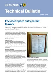
The graph shows the relationship between the vapour<br />
pressure and relative humidity at different temperatures,<br />
e.g.100% relative humidity at 10°C represents a water<br />
vapour pressure of 9.2mm Hg; at 20°C of 17.5mm Hg,<br />
2 Actually, there will be a very slight rise in vapour pressure, but this<br />
may be ignored for the purposes of the example.<br />
13
Graph 1: Relationship of vapour pressure and relative humidity at<br />
different temperatures<br />
Vapour pressure mm mercury<br />
40<br />
35<br />
30<br />
25<br />
20<br />
15<br />
10<br />
5<br />
100%RH<br />
75%RH<br />
50%RH<br />
0<br />
-5 0 5 10 15 20 25 30 35<br />
Temperature 0 C<br />
and at 30°C of 32mm Hg – i.e. an increase of 20°C has<br />
resulted in a more than three-fold increase in the waterholding<br />
capacity of the atmosphere.<br />
Condensation<br />
If air is cooled to the point where saturation (100%<br />
relative humidity) is reached, then moisture will begin to<br />
be deposited in the form of droplets or mist i.e.<br />
condensation will occur.<br />
Ship’s sweat<br />
If the air in a ship’s hold is warm and it comes in contact<br />
with the deckhead which has become cooled by the<br />
outside atmosphere, so that the temperature of the air<br />
close to the surface of the deckhead may be reduced<br />
below that at which saturation vapour pressure for that<br />
particular water content is reached, i.e. 100% relative<br />
humidity, then condensation will normally form on the<br />
deckhead in the form of sweat.<br />
Equilibrium relative humidity (water activity)<br />
Equilibrium point<br />
All biological materials normally contain a certain<br />
amount of water. The amount of moisture present at any<br />
given time is the moisture content. If the material is put<br />
in contact with dry air, then it will tend to lose a small<br />
proportion of its water to the air in the form of water<br />
vapour. This process will continue until an ‘equilibrium’<br />
of the air in contact with the material of that particular<br />
moisture content and at that particular temperature.<br />
Equilibrium relative humidity is sometimes referred to as<br />
‘water activity’. The latter is measured as a ratio rather<br />
than as a percentage thus equilibrium relative humidity<br />
of 50% is equivalent to a water activity of 0.5.<br />
Usually, with a biological cargo, the condition of the<br />
atmosphere within the cargo (that is, of the air trapped<br />
between the various particles of the cargo) is controlled<br />
largely by the condition of the cargo. In cargoes such as<br />
bulk grain, where air movement within the bulk is very<br />
restricted, the moisture content of the atmosphere within<br />
the cargo (which is also termed the ‘interstitial’ or ‘inter<br />
particular’ air) is, under normal conditions, completely<br />
controlled by the temperature and moisture content of<br />
the cargo.<br />
Experimental work with maize has made it possible to<br />
construct graphs that equate equilibrium relative<br />
humidity with moisture content at various temperatures.<br />
Such graphs are known as ‘desorption isotherms’, since<br />
all the experiments were constructed so that to achieve<br />
equilibrium relative humidity, moisture was given up by<br />
the maize to the surrounding air. If the air around the<br />
maize is wetter than the equilibrium relative humidity,<br />
then the maize will absorb moisture from the air. Such a<br />
process is known as ‘adsorption’ and a similar series of<br />
curves or isotherms can be constructed which are called<br />
‘adsorption isotherms’. The relationship between<br />
adsorption and desorption isotherms is a complex one<br />
and it is not proposed to discuss it at length in this<br />
article. However, it may be stated that under conditions<br />
of desorption, the equilibrium relative humidity at any<br />
given moisture content is slightly lower than under<br />
conditions of adsorption. Normally in the grain trade,<br />
from harvesting through to the discharge of cargo, there<br />
is a tendency for the grain to lose moisture to the<br />
surrounding atmosphere, and thus behaviour patterns<br />
should be deduced by a study of desorption isotherms.<br />
If a situation occurs where the grain is absorbing<br />
moisture from the atmosphere, strictly speaking, the<br />
behaviour pattern should be deduced by a study of<br />
adsorption isotherms.<br />
Moisture migration<br />
The mechanism of moisture migration<br />
It is necessary to understand the definition referred to<br />
above in order to appreciate the process of moisture<br />
migration. We will illustrate the mechanism by which<br />
moisture migration operates by considering a cargo of<br />
bulk maize. With this commodity migration is slow.<br />
Change of temperature – change of ERH<br />
– change of vapour pressure<br />
We have already stated that the interstitial air that<br />
occupies some 40% of the cargo space in the case of<br />
maize in bulk will contain water vapour, and the vapour<br />
pressure in this air will rapidly reach equilibrium with the<br />
moisture content of the maize. In maize with a moisture<br />
content of 14% and a temperature of 25°C, the relative<br />
humidity of the interstitial air will rapidly reach 68% and<br />
the water vapour pressure in the air at that time will be<br />
14
16.3mm Hg. A change in the temperature of the maize<br />
will result in a change of the equilibrium relative humidity<br />
and in the vapour pressure. The table below shows<br />
equilibrium temperatures for maize at 14% moisture<br />
content. The temperatures at which saturation vapour<br />
pressure occurs (i.e. 100% relative humidity) are<br />
included in the table. These temperatures are known as<br />
the ‘dew points’.<br />
Table 1. Temp / ERH / VP / DP – Relationship of maize at 14%<br />
moisture content<br />
Temp Equilibrium RH Vapour pressure Dew point<br />
°C % mm Hg °C<br />
15 60.0 7.1 7.4<br />
20 64.4 11.2 13.0<br />
25 68.0 16.3 18.7<br />
30 71.5 22.9 24.3<br />
35 75.0 31.5 30.0<br />
Argentine maize: The isotherm graph below shows equilibrium<br />
relative humidity plotted against moisture content.<br />
Moisture content absolute %<br />
17<br />
16<br />
15<br />
14<br />
13<br />
12<br />
Thus, air at 25°C and 68% equilibrium relative humidity<br />
will have a vapour pressure of 16.3mm Hg, but if this air<br />
is reduced to a temperature of 18.7°C, then moisture<br />
will be deposited because the saturation vapour<br />
pressure will then be reached. If we assume that the<br />
ship carrying this maize of 14% moisture content and of<br />
temperature 25°C passes into a region of colder water,<br />
then the outside of the cargo will assume the<br />
temperature of the cold sides of the vessel, and if we<br />
assume this to be 15°C, it can be seen from the table<br />
that such maize will have an equilibrium relative<br />
humidity of 60% and a vapour pressure of 7.1mm Hg.<br />
The cooling process of the colder sea will not<br />
noticeably affect the maize in the centre of the bulk,<br />
since maize is a poor conductor of heat. Its thermal<br />
conductivity at normal moisture contents is less than<br />
five times as great as that of loose cork insulation and<br />
only one fifth the average value for concrete. Thus the<br />
maize in the centre of the stow will still have a<br />
temperature of 25°C and the interstitial air in this region<br />
will still have a vapour pressure of 16.3mm Hg.<br />
A vapour pressure difference is therefore created,<br />
between the interstitial air in the maize in the centre and<br />
the interstitial air in the maize on the periphery of the<br />
stow. Consequently, there will be a flow of moisture<br />
vapour from the high pressure region to the low<br />
pressure region in order to equalise the pressure<br />
difference, and water will thus move from the centre<br />
towards the periphery.<br />
This movement of water from the inner portion of the<br />
cargo will have the immediate effect of causing a<br />
reduction in the vapour pressure of the air there, but<br />
equilibrium conditions will be restored as result of more<br />
water moving from the grain into the interstitial air, so<br />
that the original vapour pressure of 16.3mm Hg will be<br />
11<br />
10<br />
9<br />
o 20 C<br />
15 C<br />
o 25 o C<br />
30 o C<br />
35 o<br />
C<br />
8<br />
30 40 50 60 70 80 90<br />
Equilibrium relative humidity %<br />
maintained. Consequently, there will be continuous<br />
flow of water vapour from the warmer part of the stow<br />
to the colder part.<br />
Cargo sweat at periphery<br />
In the example which we have given, the overall effect of<br />
this transfer of moisture vapour will be to cause<br />
deposition of physical water in the periphery of the stow<br />
in contact with the cold hull. This follows from the table,<br />
which shows that a vapour pressure of 16.3mm Hg at<br />
25°C will have a dew point of 18.7°C. As this dew point<br />
is higher than the temperature of the cargo at the<br />
periphery, water will be deposited on the cargo. This<br />
illustrates the mechanism whereby ‘cargo sweat’ is<br />
produced 3 .<br />
The above example is an over-simplification of what<br />
happens in practice, since there is a tendency to set up<br />
a temperature gradient in the maize, along the route<br />
3 Studies have shown that cargo sweat, i.e. the depositing of liquid<br />
water on the surface of maize grains is extremely unlikely, either as a<br />
result of the transfer of moisture from warm ventilating air to a cold<br />
surface layer of grain, or from warm moisture-laden air rising from a<br />
bulk of warm grain towards a cold surface layer. However, moisture<br />
transfer would still occur in either situation causing the moisture<br />
content of the cold grain to rise. The effect is therefore the same.<br />
15
from the inside of the stow to the outside, and there will<br />
be a gradual drop in the temperature of the air which<br />
moves and the grain in contact with it. Hence water<br />
vapour will be absorbed en route, lowering the dew<br />
point of the air moving towards the periphery of the<br />
stow. Thus it is not possible to make an exact prediction<br />
of what conditions are necessary for cargo sweat to<br />
occur.<br />
Heating up<br />
If there is a temperature differential between the outside<br />
of the stow and the inside, then moisture migration will<br />
result from the mechanism previously described. Such<br />
moisture migration will also occur when one part of the<br />
bulk becomes heated-up for any reason, e.g. insect<br />
infestation, microbiological activity or proximity to a hot<br />
bulkhead. In all these circumstances moisture will<br />
migrate from the warmer region to colder parts of the<br />
stow.<br />
Warmer to cooler<br />
We have illustrated, taking maize as an example, the<br />
reasons why moisture migration occurs. As with maize,<br />
the problem of moisture migration is most evident with<br />
exports of biological materials from warmer climates to<br />
cooler climates. Moisture migration can occur from<br />
many causes but, however the temperature differential<br />
comes about, the result will always be (where the<br />
moisture content is uniform) a movement of moisture<br />
from the warmer to the cooler parts of the cargo.<br />
Moisture migration is observed in cargoes where<br />
‘insect infestation’ occurs. Here, centres of heating<br />
arise from the respiratory heat from the insects and<br />
moisture migrates from these spots to form a wetter<br />
shell in the cooler cargo immediately surrounding the<br />
heated zone. As heating becomes progressive, the<br />
heating zone of course expands as the wetter shell<br />
moves outwards.<br />
A second example is where ‘ship’s heat’ causes a<br />
localised rise in the temperature of the cargo in contact<br />
with the source of the heat – e.g. an uninsulated engine<br />
room bulkhead. Here moisture migrates from the warm<br />
cargo and forms a layer of increased moisture content<br />
in the cooler cargo adjacent to it.<br />
Unfortunately, the straightforward pattern of moisture<br />
movement resulting from a vapour pressure differential<br />
is not the only phenomenon that results from<br />
temperature differential in a cargo. Where temperature<br />
differentials are present, convection currents are set up<br />
owing to the fact that warm air is less dense than cold<br />
air. Thus, if heating occurs within a cargo, there will be a<br />
tendency for moisture to migrate in all directions from<br />
the heating zone. But there will also be a tendency for<br />
hot air to rise from the heating zone, to be replaced by<br />
cooler air coming in from the sides and underneath. The<br />
warm air will carry moisture with it, so that the pattern of<br />
moisture movement will be distorted in a vertical<br />
direction. In fact, where a hot spot occurs in a cargo,<br />
moisture movement is greater in a vertical direction than<br />
either laterally or downwards, because convection<br />
currents reinforce the upward movement of moisture.<br />
Thus for grain loaded warm and subjected to peripheral<br />
cooling, the major amount of moisture movement will be<br />
in a vertical direction, i.e. more water will pass towards<br />
the top of the cargo than towards the sides. If it is not<br />
possible to remove the water migrating to the top region<br />
of the cargo by ventilation, a subject that is discussed<br />
later in this report, more damage may be anticipated in<br />
the top layers than at the sides.<br />
The rate of moisture migration<br />
Having established the causes and the pattern of<br />
moisture migration, we now consider the quantitative<br />
aspects of the phenomenon.<br />
Difference in vapour pressure<br />
The rate at which moisture moves from a warm to a cold<br />
region is dependent to a large extent on the difference<br />
in vapour pressure between the warmer and colder<br />
parts of the cargo. From Table 1 it will be seen that the<br />
vapour pressure of interstitial air of a cargo of maize at<br />
14% moisture content does not increase directly with<br />
temperature. Thus an increase in temperature from<br />
15°C to 25°C will give a vapour pressure increase of<br />
9.2mm Hg, whereas a rise in temperature from 25°C to<br />
35°C will give a vapour pressure increase of 15.2mm<br />
Hg. It therefore follows, that moisture migration will be<br />
greater, all other things being equal, when moisture is<br />
moving from cargo at 35°C to cargo at 25°C than when<br />
moisture is moving from cargo at 25°C to cargo at<br />
15°C, although the temperature difference in both<br />
cases is the same. Thus, when considering rate of<br />
moisture movement within a cargo, not only is<br />
difference in temperature important, but also the ‘actual<br />
temperatures’. A further factor is of course the<br />
differential in temperature in relation to distance – thus<br />
moisture will move more rapidly from cargo at 25°C to<br />
cargo at 15°C if the distance through which it must<br />
travel is only 1m rather than 10m, because it will be<br />
obvious that the vapour pressure gradient is much<br />
greater in the former case. In this respect the ‘thermal<br />
conductivity’ of the cargo in question is of considerable<br />
importance; the lower the conductivity, the slower heat<br />
will move through a cargo, and hence the less the<br />
potential for moisture movement.<br />
Initial moisture content<br />
The initial moisture content is also important. If we<br />
consider a cargo of maize at 14% moisture content<br />
16
loaded at 35°C with its periphery cooled down to<br />
25°C, the equilibrium vapour pressures will be<br />
31.5mm Hg and 16.3mm Hg respectively, giving a<br />
differential of 15.2mm Hg. Under the same<br />
temperature conditions, but with maize at moisture<br />
content of 11%, the equilibrium vapour pressures will<br />
be 22.4mm Hg and 11.6mm Hg, giving a differential of<br />
10.8mm Hg. Thus the differential at lower moisture<br />
contents – therefore moisture movement – is less. In<br />
addition, (and this is of considerable practical<br />
importance), a much greater quantity of water can be<br />
absorbed by the cooler grain before the moisture<br />
content is raised to a level at which spoilage will<br />
commence.<br />
Compactness<br />
Because of the importance of convection currents in<br />
moving moisture, the more readily air can move<br />
through a cargo, the more rapidly moisture can be<br />
carried through that cargo in the moving air, so that all<br />
other things be in equal, there will be more rapid<br />
moisture movement through a cargo that is less<br />
compact (e.g. pellets) than through a cargo which is<br />
for example powdered, where the movement of air will<br />
be very limited.<br />
The cargo itself<br />
Finally, when considering the rate at which moisture<br />
may move through a cargo, it is necessary to consider<br />
the nature of the cargo itself. Thus cargo such as grain,<br />
which consists of seeds grown in dry climate, has<br />
comparatively low moisture content and the seed itself<br />
has a protective outer skin, which is relatively<br />
impermeable to moisture. In fact, one of the main<br />
purposes of this skin is to prevent the seed from drying<br />
out, either during growth or subsequent to growth and<br />
prior to germination. Thus moisture is released rather<br />
slowly from seed products such as wheat and maize<br />
when compared with other products, particularly those<br />
grown under wet conditions in the tropics, where there<br />
is no natural necessity to conserve moisture. Similarly,<br />
whole grain will lose moisture much more slowly than<br />
grain that has been milled or pulverised in some way,<br />
where the natural protective coating is disrupted.<br />
Quantitative data for the release of moisture from<br />
various products is scanty, and direct comparisons are<br />
particularly difficult. We have therefore not been able<br />
to give examples to illustrate the above.<br />
When studying moisture movement there are two<br />
factors of interest. The first is the actual quantity of<br />
water moving from one place to another. The second is<br />
the rate at which the ‘zone of enhanced moisture’<br />
moves forward. We have done some work on the latter<br />
factor with maize.<br />
It was found that in 28 days, a zone of enhanced<br />
moisture had moved approximately 1m in a vertical<br />
direction (i.e. with convection currents reinforcing the<br />
moisture movement) from the hot spot. The<br />
temperature differential in this experiment was from<br />
40°C to 21°C over a distance of approximately 1.25m.<br />
The actual quantities of water involved could not be<br />
accurately determined. There is no doubt whatsoever,<br />
that with other types of cargo both the rate of movement<br />
and the quantities of water moved would have been<br />
many times greater than was found with maize.<br />
Therefore, when considering the significance of<br />
potential moisture migration in a cargo, it is necessary<br />
to consider the vapour pressure differential in relation to<br />
the distance between the hotter and colder zone, the<br />
temperature of the hotter material and the temperature<br />
of the colder material to which moisture is migrating, the<br />
initial moisture content, the nature of the cargo and the<br />
ease with which air may move through it.<br />
Practical application<br />
To take simple practical illustrations of this, it is not<br />
unusual to shift bulk grain round the world in tankers<br />
(where of course there is no possibility of ventilation)<br />
and to store bulk grain in unventilated silos for long<br />
periods of time where considerable differences in<br />
temperature can occur between summer and winter.<br />
This is only possible because under normal conditions,<br />
the rate of moisture migration in bulk grain is low. When<br />
cargoes of cocoa or rice are considered, the rate of<br />
moisture migration is many times greater. It would of<br />
course be courting disaster to attempt to carry cocoa<br />
from West Africa to Northern Europe in tankers. Thus<br />
the quantitative aspects of moisture migration are of<br />
primary importance when considering the best method<br />
of carrying a particular cargo on a particular voyage.<br />
No general rules<br />
In the following section, we discuss ventilation in<br />
general terms in order to illustrate how the use of<br />
ventilation can assist in minimising the deleterious<br />
effects of moisture migration. Because of the many<br />
factors involved however, it would be unwise to attempt<br />
to formulate general rules for the carriage of cargo to<br />
minimise the effects of moisture migration.<br />
Grain in bulk<br />
General<br />
Vessels which carry grain in bulk vary in their capability<br />
for ventilating the cargo. Considerable quantities of<br />
grain are carried in tankers with no ventilation<br />
whatsoever. Sometimes grain is carried in vessels fitted<br />
with a sophisticated Cargocaire system of surface<br />
ventilation, which also has facilities for pre-conditioning<br />
17
the ventilating air. Other vessels have fan-assisted<br />
surface ventilation and quite a large proportion have<br />
the normal type of surface ventilation through cowls,<br />
unassisted by any mechanical effort, the flow of air<br />
being dependent upon the movement of the ship.<br />
Some bulk carriers which successfully carry many<br />
thousands of tonnes of grain etc. have no means<br />
whatsoever of ventilating the surface of the cargo.<br />
It should be pointed out, that vast quantities of grain<br />
are transported around the world, and in the great<br />
majority of instances, the cargoes outturn in a sound<br />
condition. This is true also of tankers, which indicates<br />
that surface ventilation is not a necessary pre-requisite<br />
to successful carriage.<br />
On numerous occasions, claimants have been advised<br />
by their experts that spoilage of grain in transit has<br />
resulted from unsatisfactory ventilation. Alternatively, it<br />
has sometimes been suggested that lack of ventilation<br />
has exacerbated damage caused by other factors.<br />
We consider that a bulk cargo of grain, if stowed in<br />
accordance with SOLAS Regulations – see later –<br />
cannot be significantly affected by surface ventilation<br />
or from a lack of it.<br />
Oxley 4 states:<br />
“...popular opinion greatly exaggerates the virtues<br />
of ventilation…gaseous diffusion and heat<br />
movement in grain are both exceedingly slow and in<br />
the absence of mechanical means of forcing air<br />
through the bulk, changes in the atmosphere at the<br />
surface have a negligible effect on the intergranular<br />
atmosphere and on the water content or<br />
temperature of the grain.”<br />
In order to reduce moisture movement and its effects<br />
within a grain cargo, it is necessary to reduce the<br />
moisture content throughout. This will not only cut<br />
down the rate of moisture movement but will also mean<br />
that greater variations in moisture can occur within the<br />
cargo without commercial loss caused by the<br />
development of microbiological activity. Alternatively,<br />
the temperature differential may be reduced by cooling<br />
the bulk of the grain; this again would cut down the<br />
amount of moisture movement. A reduction in moisture<br />
content and a reduction in temperature could both be<br />
achieved by passing significant quantities of air<br />
through the cargo. Through ventilation, although<br />
possible in some silos ashore, is not possible onboard<br />
ship. In practice, onboard ship, only surface ventilation<br />
is available to attempt to control the deleterious<br />
peripheral effects resulting from moisture migration in<br />
bulk grain.<br />
4 Scientific Principles of Grain Storage, Liverpool, 1948, p23<br />
Cargo sweat<br />
In the case of tankers, all are agreed that nothing can be<br />
done about ship’s sweat should it occur, but it is<br />
suggested in the case of vessels fitted with natural or<br />
mechanical ventilation, that the moist air may be<br />
continuously removed from the headspace above the<br />
cargo and the quantity of condensation occurring on<br />
the deckhead accordingly reduced or eliminated.<br />
It must, however, be remembered in these<br />
circumstances that the air used for ventilation is at the<br />
same temperature as, or below, the temperature of the<br />
deckhead and hatchcovers. If the ventilating air is cool,<br />
then the immediate effect will be to take up moisture<br />
vapour by diffusion from the interstitial air in the surface<br />
layers of the cargo, because the vapour pressure of the<br />
interstitial air will be higher than the vapour pressure of<br />
the ventilating air. At the same time, the surface of the<br />
cargo will be cooled, both directly by contact with the<br />
cooler ventilating air and as a result of evaporation of<br />
moisture. The temperature of the surface layer of the<br />
cargo may therefore be reduced below the dewpoint of<br />
the warm moist air rising from within the bulk. Water will<br />
then condense in the cooler surface layers of the cargo<br />
thus producing a wet cake just below the surface.<br />
Microbiological spoilage will eventually occur in this<br />
wet cake. Even if no condensation occurs in the surface<br />
layer, the moisture content of these layers may rise as a<br />
result of absorption of moisture, to a level where<br />
microbiological activity can commence – although this<br />
damage does not arise strictly from ‘cargo sweat’.<br />
Thus, if the external ambient conditions are such that<br />
ship’s sweat would occur in the absence of ventilation,<br />
then cargo sweat will frequently occur just below the<br />
surface if ventilation is employed. This means in fact<br />
that, under these circumstances damage will result<br />
whether ventilation is used or not.<br />
Surface ventilation is also claimed to be useful in<br />
removing heat from cargo that is heating, thus<br />
minimising the increase in temperature which might<br />
cause further deterioration of the cargo. It is, however,<br />
generally agreed that heat transfer through bulk grain is<br />
a very slow process. Work carried out using a vertical<br />
heat transfer system with a temperature differential of<br />
20°C indicted that about 32 days continuous heating<br />
was required before there was a rise in temperature of<br />
3°C in maize one metre from the heat source. This<br />
practical data is in line with calculations published by<br />
Leninger 5 and the views of Oxley (ibid). Indeed, it is<br />
because of this very fact that microbiological spoilage<br />
does produce serious heating up. Hence surface<br />
5 Ayerst & Leniger: Report on Heat Damage to Argentinian Maize<br />
during shipment to Europe, December 1967<br />
18
ventilation cannot significantly affect a heating process<br />
which is occurring more than about a metre below the<br />
surface. What can occur when the surface of a heating<br />
cargo is continuously cooled by ventilation, is that the<br />
vapour pressure differential between the interior of the<br />
cargo and the periphery is maintained and consequently<br />
the phenomenon of moisture migration is encouraged.<br />
Stowage regulations<br />
The irrelevance of surface ventilation to the carriage of<br />
grain is apparent from the stowage regulations in force<br />
in all major grain exporting countries, which insist that<br />
the vessel be stowed so that shifting of the cargo is<br />
impossible. Under these regulations, a ship’s grain<br />
carrying compartments are classified as either partly<br />
filled or full. Grain in partly filled compartments must be<br />
levelled and topped off with bagged grain or other<br />
suitable cargo, tightly stowed and extending to a height<br />
of 1-2m above the bulk. The bagged grain or other<br />
suitable cargo must itself be supported by a platform<br />
made either of close boarded wood, or strong<br />
separation cloths laid over the whole surface of the bulk<br />
cargo.<br />
These regulations provide that in compartments totally<br />
filled with grain, the grain shall be trimmed so as to fill all<br />
the spaces between the beams, in the wings and ends.<br />
Further, to ensure that the compartment is maintained<br />
fully filled during the voyage, the compartment must be<br />
equipped with a feeder, from which grain can flow into<br />
the compartment if the cargo settles during the voyage.<br />
Alternatively the grain in the area of the hatch may be<br />
trimmed hard up to the deckhead beyond the hatchway<br />
to form a saucer. This saucer and the hatchway above is<br />
then filled with bagged grain or other suitable cargo<br />
extending to a height of at least two metres in the centre<br />
of the saucer. The bagged grain or other suitable cargo<br />
must itself be stowed tightly against the deckhead, and<br />
the longitudinal bulkheads, the hatch beams and hatch<br />
coamings.<br />
The express purpose of the regulations, is to reduce to a<br />
minimum – and if possible to eliminate – the head space<br />
between the surface of the cargo and the overlying<br />
deck. With cargo stowed correctly in this way there is<br />
no possibility of effective surface ventilation.<br />
Other cargoes where moisture<br />
migration is substantially more<br />
rapid<br />
We took grain stowed in bulk as a first example because<br />
this probably represents a cargo in which moisture<br />
migration is the slowest compared with other cargoes<br />
which may be carried both in bulk and in bags.<br />
The rate of moisture migration and the amount of<br />
moisture moving in other cargoes may be higher<br />
because, on the one hand, of differences in voyage and<br />
loading temperature, and, on the other, of the physical<br />
nature of the cargo stowed.<br />
A typical cargo in which rapid moisture movement can<br />
occur is bagged rice. This cargo is usually loaded at a<br />
high temperature and at a moisture content just below<br />
the critical level which is about 14%. If the cargo is<br />
stowed in a block, stow temperature changes in the<br />
external atmosphere and sea water may set up serious<br />
temperature gradients between the centre and<br />
peripheral regions of the stow, with the result that<br />
massive moisture movement occurs leading to the<br />
formation of both cargo sweat and ship’s sweat. This in<br />
turn results in part of the cargo becoming excessively<br />
wetted. Microbiological deterioration occurs in the<br />
wetted cargo.<br />
In order to prevent or minimise this problem, bagged<br />
rice is normally stowed so that linked vertical and<br />
horizontal ventilation shafts are incorporated in the stow<br />
to facilitate moisture movement from the bulk to the<br />
external atmospheres.<br />
Even with this form of stowage, when a rapid fall in<br />
external temperature occurs, as might be experienced<br />
with a vessel sailing to Northern Europe in the winter,<br />
serious sweat formation can result. This is well known<br />
to surveyors working in Northern European ports<br />
A similar phenomenon also occurs with bagged cocoa<br />
shipped from West Africa to Northern Europe. Here,<br />
the cargo is artificially dried so that ventilation in the<br />
early stages of a voyage, i.e. before about the latitude of<br />
Dakar, can result in the cargo picking up moisture from<br />
the atmosphere and is not normally recommended.<br />
After this, ventilation may be used to minimise sweat<br />
formation; but it must be borne in mind that cooling the<br />
surface of the cargo encourages moisture migration by<br />
increasing the temperature gradient between the bulk<br />
and the surface of the cargo, and may also result in the<br />
formation of cargo sweat. Thus, shock cooling of the<br />
surfaces of the cargo should be avoided and ventilation<br />
during the hours of darkness or during cold weather is<br />
probably best avoided.<br />
It can be shown by calculation that, in any event, when<br />
cold conditions are encountered, the rate of emission of<br />
moisture from a normal cargo of cocoa can be<br />
substantially higher than the rate at which such<br />
moisture can be removed by a normal ventilating<br />
process, even assuming the ventilating atmosphere<br />
becomes saturated as it passes over the cargo. Thus,<br />
19
sweat damage under some circumstances is inevitable.<br />
It will be seen from the foregoing sections that moisture<br />
migration within, and from, a water-holding cargo must<br />
occur as the vessel moves through different<br />
climatological regions. The purpose of ventilation is to<br />
minimise damage to the cargo resulting from this<br />
moisture migration. However, it will also be seen that<br />
such ventilation cannot always be completely effective<br />
and under some circumstances can be at least partially<br />
self-defeating. It follows that with certain cargoes,<br />
especially those where moisture movement is rapid,<br />
such as bagged rice and cocoa beans – which have<br />
been taken as examples in this article – no normal<br />
ventilating system can prevent cargo damage occurring<br />
as result of the conditions encountered during certain<br />
types of voyage.<br />
The rate of moisture migration and the amount of<br />
moisture moving in water-holding cargoes will vary<br />
between the two extremes of bulk grain on the one hand<br />
and rice or cocoa beans on the other; but because of<br />
the wide variety of voyages undertaken and types of<br />
product carried, it is impossible to give precise<br />
recommendations (except under special circumstance)<br />
as to when ventilation should be practised. Many<br />
surveyors at present, work on the ad hoc basis that<br />
ventilation should be practised whenever weather<br />
conditions permit and, if under these circumstances<br />
sweat is formed, they consider the ship’s personnel<br />
have taken all reasonable steps to ensure a sound<br />
outturn. This is subject to the qualification that what is<br />
crudely termed ‘moisture migration in reverse’ does not<br />
occur; in other words, that the ventilation air introduced<br />
into the hold does not give up its moisture to the cargo.<br />
Moisture will be absorbed into cargo whenever the<br />
dewpoint of the interstitial air is lower than the dewpoint<br />
of the ventilating air. Unfortunately, however, it is<br />
virtually impossible onboard ship to measure the<br />
dewpoint of the interstitial air, and thus the decision of<br />
when or when not to ventilate cargoes of this type must<br />
still be based on a compromise between the scientific<br />
theory of the text book and the practical experience of<br />
those engaged in the trade.<br />
Ventilation experiments<br />
Introduction<br />
When maize arrives damaged by heating, the cargo<br />
interests frequently allege that the damage is caused by<br />
unsatisfactory ventilation. Thus it may be suggested<br />
that inadequate ventilation has permitted sweat to form<br />
on the ship’s structure, with the result that the cargo has<br />
been wetted on the surface. Alternatively it may be<br />
claimed that, because the ventilation is inadequate, the<br />
heat produced in a cargo was not removed, with the<br />
result that the damage becomes progressive.<br />
Damage as a result of ship’s sweat is readily<br />
recognisable, and takes the form of a layer of mouldy<br />
grain on the surface of the cargo.<br />
In many instances, particularly where the amount of<br />
damage is appreciable, a defence against a claim for<br />
such damage is to demonstrate that if in fact ventilation<br />
had been practised, the air would have been sufficiently<br />
cold to have cooled the top layer of grain with the result<br />
that moisture in vapour form would have migrated from<br />
within the bulk to the cooler surface. But, on<br />
encountering the cooler cargo in the surface layer, the<br />
vapour would have given up its moisture in the form of<br />
condensation on the cargo.<br />
Thus instead of ‘ship’s sweat’, there would have been<br />
‘cargo sweat’ – the total damage however, about the<br />
same .<br />
This is, simply stated, the theory of ‘moisture migration’,<br />
which was judicially considered in John v The Turnbull<br />
Scott Shipping Co. Ltd. (The Flowergate) [1967] 1<br />
Lloyd’s Rep.1 – see in particular, the evidence of<br />
Dr Milton, quoted on pages 32 and 33 of the<br />
judgement.<br />
Serious claims for damage however, normally arise<br />
from heating up within the bulk of the cargo and the<br />
question of efficacy of ventilation in removing heat and<br />
minimising progressive heating up in such instances<br />
had never been thoroughly examined on a scientific<br />
basis. It was therefore decided to examine the changes<br />
in temperature within the bulk of maize cargoes during<br />
shipment from South America to Europe.<br />
Conclusion<br />
These experimental shipments indicated that maize of<br />
low moisture content, loaded cool, will carry well over a<br />
relatively long voyage whether or not the surface of the<br />
bulk is ventilated. They showed further that it is only the<br />
surface of the cargo that responds to ventilation, the<br />
bulk of the stow remaining unaffected. This perhaps, is<br />
not surprising when one remembers how resistant<br />
maize is to the transfer of heat; its coefficient of thermal<br />
conductivity is less than that of asbestos, and as an<br />
insulator, it is about one-third as good as cork.<br />
In general it can be said that the experiments confirmed<br />
the view previously expressed by Dr Milton, namely that<br />
ventilation is irrelevant to the carriage of maize in bulk.<br />
This article and full details of these experiments are available under<br />
Moisture migration and surface ventilation in the Loss Prevention –<br />
Carefully to Carry section of the Club web website www.ukpandi.com<br />
20
Measurement<br />
of bulk cargoes<br />
Draught surveys – practice<br />
●<br />
●<br />
●<br />
●<br />
●<br />
The master of a vessel should be advised in<br />
adequate time that a draught survey will be taking<br />
place. If it is an initial light ship survey, he should be<br />
requested, subject to the safety of the vessel, to<br />
ensure that individual ballast tanks are either fully<br />
pressed up or empty – that the vessel is upright, and<br />
with a trim which is within the limits of the tank<br />
calibration tables.<br />
When draught surveys are undertaken by<br />
independent surveyors, co-operation of the ship’s<br />
officers is essential.<br />
Independent surveys should be undertaken<br />
together, during the relative survey sections, with the<br />
vessel’s chief officer and chief engineer or their<br />
appointed respective deputies.<br />
Before undertaking the survey, it is recommended<br />
that the surveyor makes time to inspect a general<br />
arrangement plan in order to confirm the number<br />
and position of the various ballast, fresh water and<br />
oil bunker tanks on the vessel.<br />
Equipment which may be used in the survey:<br />
●<br />
●<br />
●<br />
●<br />
●<br />
●<br />
●<br />
●<br />
●<br />
Strong torch<br />
Patent draught mark indicator or measuring<br />
devices (draught tubes, indicators etc)<br />
Calibrated inclinometer or manometer<br />
Steel tape measure with plumb bob / stainless<br />
steel sounding tape with brass plumb bob<br />
(preferably calibrated)<br />
Sea water sampling bucket or can of sufficient<br />
volume<br />
Calibrated patent draught survey hydrometer<br />
Calibrated salinity refractometer<br />
Ballast water-sampling device<br />
Computer / calculator.<br />
Reading the draught marks<br />
●<br />
At the time of reading the draught marks, the vessel<br />
should be upright with a minimum of trim. The trim at<br />
survey should never exceed the maximum trim for<br />
which corrections may be included in the vessel’s<br />
stability book.<br />
●<br />
●<br />
●<br />
●<br />
The vessel should ideally be lying in still, calm water.<br />
Otherwise errors, without ease of correction, from<br />
reading the draught marks can result. For example:<br />
●<br />
●<br />
●<br />
●<br />
Vessels lying at exposed berths or anchorages<br />
where wave and swell surface disturbance is<br />
almost inevitable; even to the extent that the<br />
vessel may be rolling and pitching. In these<br />
circumstances it is usual to assess the actual<br />
mean water level over a number of readings to be<br />
at two-thirds of the distance between the lowest<br />
and highest levels of water as seen against the<br />
draught marks. Some experts advocate that, after<br />
studying wave patterns, a mean of the average<br />
highest and lowest draught readings should be<br />
used<br />
Vessels which are lying at a river berth or in tidal<br />
conditions when strong currents are running.<br />
Under these conditions the draught marks should<br />
ideally be read over periods of slack water<br />
(provided that at a low water slack there is<br />
sufficient under-keel clearance)<br />
Currents of appreciable strengths are likely to<br />
cause the vessel to change trim or pitch slightly<br />
and/or sink bodily into the water from her static<br />
draught (‘squat’). This phenomenon becomes<br />
more pronounced in shallow waters (shallow<br />
water effect)<br />
Strong currents will result in raised water levels<br />
against the leading edge of a stationary vessel<br />
lying in flowing water. This is especially true<br />
when the flow is in the direction of a vessel’s<br />
bulbous bow.<br />
Draught marks must be read on both sides of the<br />
vessel: forward port and starboard; amidships port<br />
and starboard, and; aft port and starboard or,<br />
alternatively, if additional marks are displayed on<br />
large vessels at all the designated positions.<br />
Should draught marks not be in place amidships,<br />
distances from the deck line to the water line on<br />
both sides of the vessel must be measured. The<br />
amidships draughts can then be calculated from<br />
load line and freeboard data extracted from the<br />
vessel’s stability booklet.<br />
Draught marks should be read with the observer as<br />
close to the water line as is safe and reasonably<br />
possible, in order to reduce parallax error.<br />
Although it is common practice to read the offside<br />
draught marks from a rope ladder, a launch or small<br />
boat provides a more stable environment and brings<br />
the observer to a safer position closer to the water<br />
line.<br />
21
●<br />
A vessel’s remote draught gauge should never be<br />
used for surveys, due to lack of the necessary<br />
accuracy and the possibility of errors, which may<br />
accumulate over the working life of the instrument.<br />
●<br />
When adverse weather conditions are being<br />
experienced, access to the offside draught marks<br />
may prove difficult or impossible. At these times the<br />
draughts on the nearside can be read and the<br />
offside draughts calculated using a manometer.<br />
This method should never be used when the offside<br />
draughts can be safely observed and accurately<br />
read. If, as a final resort, this method cannot be<br />
undertaken, the use of a fully calibrated<br />
inclinometer, graduated to minutes of arc, is strongly<br />
recommended. The type of inclinometer fitted to<br />
vessels is not usually of sufficient accuracy to be<br />
used.<br />
Density of the water in which the<br />
vessel is floating<br />
Above: Manometer showing plastic tubing (30-40 m long), fitted at<br />
each end with a valve and scale. The valves are to allow the water in the<br />
tube to be retained without any air bubbles in it when the device is not<br />
in use<br />
●<br />
It is prudent to obtain samples of water in which the<br />
vessel is floating at, or very close to, the time at<br />
which the draught marks are read. This is<br />
particularly relevant when the vessel is lying at a<br />
estuarial or river berth when density of the water<br />
may be changing, due to the ebb or flow of the tide.<br />
Below: Manometer, showing scale and water level. When a scale is<br />
fitted and used for the reading care must be taken that the scale is fixed<br />
at the same height on each side<br />
●<br />
Depending upon the length of the vessel under<br />
survey, a number of samples, say between one and<br />
three, should be taken. In order to overcome the<br />
problem of layering, the samples should be<br />
obtained using a closed sampling can at a depth of<br />
approximately half the existing draught of the vessel.<br />
Alternatively, a slow-filling container can be used to<br />
obtain an average sample from keel to waterline.<br />
●<br />
When reading the hydrometer floating in the sample<br />
of water, the eye of the observer should be as close<br />
to the water level as possible, to avoid parallax<br />
errors and also to avoid further errors due to the<br />
meniscus.<br />
Ballast water tanks<br />
●<br />
Ballast water tanks including peaks, even those said<br />
to be empty, must be carefully sounded or proven to<br />
be full by pressing up and overflowing from all air<br />
pipes when local regulations permit. If the ballast<br />
hold contains ballast water, this compartment must<br />
not be fully pressed up but be carefully sounded and<br />
the weights of the water carefully calculated.<br />
●<br />
Spaces such as the duct keel and voids – especially<br />
those of the lower stools situated at the base of<br />
22
●<br />
transverse bulkheads, between cargo holds – must<br />
be checked when safe to do so, and proved in<br />
same condition at initial and final surveys.<br />
These voids often contain the manhole access<br />
covers to the adjacent double-bottom tanks. If<br />
these covers are not totally watertight, then the<br />
voids will flood, or partially flood, during ballasting<br />
or pressing up of the tanks, potentially resulting in<br />
huge errors in the lightship or ballast survey.<br />
As noted above, the calculation of the weight of<br />
ballast water is undoubtedly the most usual source<br />
of errors which may result in very large, and<br />
unacceptable, inaccuracies of the cargo quantity as<br />
calculated by draught survey.<br />
Density of the ballast water<br />
●<br />
●<br />
●<br />
It should be established, with the chief officer,<br />
where the various ballast tanks were filled. If from a<br />
single source, the sea, a few random samples of<br />
the water will confirm its density. If from different<br />
sources, docks or rivers, etc samples must be<br />
taken from the tanks containing water from these<br />
various sources and relevant densities of the water<br />
in individual tanks established.<br />
Do not overflow the tanks substantially to obtain<br />
samples unless local regulations permit; instead<br />
use sampling equipment suitable for tanks that are<br />
only partially filled.<br />
When small samples are obtained, use a salinity<br />
refractometer to establish density (see below).<br />
When larger samples have been obtained, a<br />
draught survey hydrometer may be used. See<br />
details above.<br />
Establishing the correct weights<br />
of oils on board<br />
●<br />
●<br />
●<br />
This can be established either by sounding or<br />
ullaging of the tanks or, in the case of the engine<br />
room daily service and settling tanks, by reading<br />
the gauges.<br />
The volumes of oils in each and every tank should<br />
be measured and recorded.<br />
The relative densities of the most recently delivered<br />
oils on board can be obtained from the bunker<br />
delivery certificates. However bunkers are almost<br />
inevitably mixed with oils already on board, the<br />
densities of which are likely to differ. The relative<br />
density of the contents may be calculated using the<br />
following formula:<br />
●<br />
RD of tank contents at survey =<br />
(Old oil volume x Old RD) + (New bunker volume x New RD)<br />
Total volume of oil in tank<br />
After completion of the bunker survey the totals of<br />
each oil found must be agreed with the chief<br />
engineer and the master.<br />
Calculations and associated<br />
corrections of vessel’s<br />
displacement from draught<br />
readings<br />
●<br />
●<br />
●<br />
●<br />
Before extracting hydrostatic data from the vessel’s<br />
stability book, care should be taken by surveyors to<br />
familiarise themselves with the format and methods<br />
used to display the various particulars, especially the<br />
means of depicting positions of LCF (longtitudinal<br />
centre of flotation) etc, relative to amidships or<br />
alternatively the after perpendicular.<br />
When using a recommended draught survey<br />
computer programme or alternatively calculating<br />
directly from data extracted from the hydrostatic<br />
particulars contained within the vessel’s stability<br />
book it is essential that the data is carefully and<br />
properly interpolated or, in what should prove to be<br />
a rare event, extrapolated.<br />
As mentioned below, one of the areas where<br />
significant errors often result is from the incorrect<br />
application of the sign in respect of the position of<br />
the LCF (in the first trim correction).<br />
When undertaking initial and final ‘displacement<br />
draught surveys’ to establish weight(s) of cargo<br />
loaded, or alternatively unloaded, the difference<br />
between the net displacement weights provides the<br />
‘total cargo’ quantity. Nonetheless it is<br />
recommended for a cross check that, at the light<br />
ship / ballast survey, the vessel’s light ship weight is<br />
deducted from net displacement found. The<br />
resultant then provides the vessel’s ‘constant’ at that<br />
time. These unknown weights might also be termed<br />
the vessel’s ‘stores variable’. Although variable, for a<br />
number of reasons as later discussed, it should<br />
serve as a guide to the accuracy of the light ship /<br />
ballast survey.<br />
Comparison between ‘stores variable’ quantities, or<br />
mean thereof, established at previous surveys<br />
should be treated with caution unless the variable is<br />
a direct comparison that can be made. For example,<br />
all surveys include a check and a record of the<br />
engine lubricating oil held in storage tank(s), etc.<br />
23
Occasionally, surveyors report a ‘negative’ stores<br />
variable which is theoretically impossible unless, in<br />
extremely rare instances, the vessel had been<br />
subject to modification, and large quantities of<br />
structural steel removed, without being subject to a<br />
further inclining experiment and commensurate<br />
correction of the relevant data contained in the<br />
vessel’s stability book.<br />
Charterparties often contain reference to an<br />
approximate quantity for the vessel’s ‘constant’,<br />
which may well create a discussion between master<br />
and surveyor should the constant found by survey to<br />
be substantially larger than that quoted by the<br />
owners. The surveyor, after relevant checks, should<br />
remain confident in the figure obtained, but always<br />
record on documents issued to the master and<br />
clients, any unusual factors or difficulties<br />
experienced during survey. These include any<br />
differences between surveyors, should owners,<br />
charterers or shippers each appoint separate survey<br />
companies to act on their behalf.<br />
Documentation<br />
●<br />
●<br />
●<br />
At completion of survey, a ‘survey work sheet’ or<br />
computer printout should be placed on board the<br />
vessel recording the data and calculations used to<br />
obtain the cargo loaded / unloaded quantity. This<br />
document is usually produced by individual survey<br />
companies, or by shipping companies for use by<br />
their officers.<br />
A formal ‘survey report’ should be submitted to<br />
clients at a later date. Specific formal documentation<br />
has been drawn up, amongst others by IMO, United<br />
Nations Economic Commission for Europe and<br />
various P&I Clubs.<br />
The formal report document should not only include<br />
details of the survey, but also:<br />
●<br />
●<br />
●<br />
●<br />
●<br />
●<br />
●<br />
Dates and times of surveys<br />
Vessel particulars<br />
Ship’s location<br />
Weather conditions (and whether these were<br />
within acceptable limits)<br />
Sea conditions (and whether these were within<br />
acceptable limits)<br />
Tidal/current conditions (and whether these were<br />
within acceptable limits)<br />
A record of any difficulties or defects in a ship’s<br />
documentation or equipment which might cause<br />
the calculated weight by draught displacement<br />
survey to be outside acceptable limits of normal<br />
draught survey measurement error.<br />
Expert opinion<br />
Surveys must be carried out to the very best of the<br />
surveyors’ ability, with each part of the survey<br />
conducted as accurately as possible in order to<br />
minimise procedural and/or measurement errors which<br />
could effect the quantity of cargo recorded by survey as<br />
being loaded or discharged.<br />
The final report should include details of any defect or<br />
circumstance regarding weather, surface water, tides /<br />
currents or on board conditions which the surveyor<br />
considers might well influence the result adversely.<br />
Cumulative errors<br />
● Errors can occur when reading and correcting the<br />
draughts. The final fully corrected 3/4 mean draught<br />
should be within +/- 10 mm of the true mean<br />
draught.<br />
●<br />
●<br />
●<br />
Errors of calculation. The main error to be avoided in<br />
this section is that of incorrectly positioning the LCF<br />
relative to LBP/2 the amidship point.<br />
Error of the water density in which the vessel is<br />
floating. Always ensure an average sample, or<br />
alternatively the average of a number of water<br />
samples are obtained and the correct type of<br />
certificated hydrometer is used to obtain the density.<br />
Sounding of tanks. Leaving aside documented<br />
tables which may not be accurate, the way of<br />
avoiding the main errors in this section of the survey<br />
is by ensuring, as best possible, that all volumes of<br />
liquids, especially ballast water, on board are both<br />
correctly quantified and attributed with correct<br />
densities. These factors, particularly when applied<br />
to ballast water, undoubtedly contribute to the<br />
largest number and degree of errors likely to be<br />
encountered in draught surveying.<br />
Bearing these reservations in mind, a well conducted<br />
draught survey under reasonable prevailing<br />
conditions is capable of achieving an absolute accuracy<br />
of +/- 0.5%.<br />
See following pages for a worked example<br />
A full version of this article is available in the Loss Prevention –<br />
Carefully to Carry section of the Club website, www.ukpandi.com,<br />
under Miscellaneous – Measurement of bulk cargoes<br />
24
Worked example<br />
From the following information calculate the corrections to perpendiculars and the draughts at the<br />
perpendiculars. Also calculate the true trim.<br />
Vessel LBP 181.8 metres Density at the time of draught reading 1.0185 t/m 3<br />
port side stbd side distance marks from perp.<br />
Forward draughts; 4.61m 4.65m Fd = 2.94 m aft<br />
Midships draughts 4.93m 5.10m Md = 1.44 m aft<br />
Aft draughts 5.58m 5.60m Ad = 7.30 m forward<br />
Forward mean = (4.61 + 4.65) / 2 = 4.63m<br />
Midships mean = (4.93 + 5.10) / 2 = 5.015m<br />
Aft mean = (5.58 + 5.6) / 2 = 5.59m<br />
So apparent trim is: 5.59 - 4.63 = 0.96m<br />
And LBM is: 181.8 - 2.94 - 7.30 = 171.56m<br />
Forward corr’n= Apparent trim x Fd = 0.96 x -2.94 = -0.0165m<br />
LBM 171.56<br />
Midships corr’n = Apparent trim x Md = 0.96 x -1.44 = -0.0081m<br />
LBM 171.56<br />
Aft corr’n = Apparent trim x Ad = 0.96 x 7.3 = +0.0408m<br />
LBM 171.56<br />
Now:<br />
Forward draught is 4.63 – 0.0165 m = 4.6135 m<br />
Midships draught is 5.015 – 0.0081 m = 5.0069 m<br />
Aft draught is 5.59 + 0.0408 m = 5.6308 m<br />
True trim is 5.6308 – 4.6135 m = 1.0173 metres = 101.73 cm<br />
¾ mean draught = (6 x 5.0069) + 4.6135 + 5.6308 = 5.0357 m<br />
8<br />
From the original survey the following data was given in the vessels hydrostatic particulars:<br />
Scale density of hydrostatic particulars 1.025 t/m 3<br />
Draught Displacement TPC LCF Draught MCTC Draught MCTC<br />
5.00 19743 42.32 -4.354 5.50 445.5 4.50 434.9<br />
5.10 20167 42.37 -4.289 5.60 446.6 4.60 435.9<br />
The stability book stated that a negative (-) sign for Lcf indicated forward of midships.<br />
Interpolating the data from the table (it is easier to use centimetres in the interpolation rather than metres)<br />
The difference in the tabulated draughts is 10 cm and the draught we are looking for is 3.57 cm more than<br />
5 metres<br />
continued over<br />
25
Therefore:<br />
Displacement for<br />
5.0357 m draught = 19743 +(20167-19743) x 3.57 = 19894.37<br />
TPC for 5.0357 m draught = 42.32 +(42.37-42.32) x 3.57 = 42.338<br />
LCF for 5.0357 m draught = - 4.354 +(4.354-4.289) x 3.57 = - 4.331 (for’d of mid)<br />
MCTC for 5.0357 +50 cms = 445.5 +(446.6-445.5) x 3.57 = 445.89<br />
MCTC for 5.0357 – 50 cms = 434.9 +(435.9-434.9) x 3.57 = 435.26<br />
Therefore (dm~dz) = 10.63<br />
The first trim correction is = 101.73 x –4.331 x 42.338 = - 102.61tonnes<br />
10<br />
10<br />
10<br />
10<br />
10<br />
181.8<br />
Second trim correction = 1.0173 2 x 50 x 10.63 = +3.03 tonnes<br />
181.8<br />
Then vessels displacement at a density of 1.025 t/m 3 is calculated as follows:<br />
Displacement for 5.0357m = 19894.37 tonnes<br />
First trim correction = -102.61 tonnes<br />
Second trim correction = +3.03 tonnes<br />
Corrected displacement in salt water = 19794.79 tonnes<br />
This is the weight of the ship at the draught if it was in salt water of density 1.025 t/m 3 , which is the density of<br />
the ship’s hydrostatic scale.<br />
However it is floating in water of apparent density 1.0185 t/m 3 .<br />
So true displacement = 19794.79 x 1.0185 = 19669.26 tonnes<br />
1.025<br />
26
Silver nitrate test<br />
For the detection of<br />
seawater contamination in<br />
cargoes<br />
A solution of silver nitrate in distilled water is regularly<br />
used as a simple test for the detection of seawater<br />
contamination of ships’ cargoes. Whilst the test is a<br />
useful preliminary test for saline contamination it should<br />
be considered as indicative only. It has limitations and<br />
should not be relied on as definitive proof of saltwater<br />
contamination; more detailed laboratory analysis will be<br />
required to confirm this.The reaction is shown below.<br />
This reaction results in the clear test solution turning a<br />
cloudy white as insoluble silver chloride is displaced out<br />
of the solution.<br />
Silver nitrate + Sodium chloride (salt)<br />
(clear solution)<br />
(contamination)<br />
Sodium nitrate + Silver chloride<br />
(clear solution)<br />
(insoluble white precipitate)<br />
In order to undertake a ‘spot’ test in situ, surveyors will<br />
normally carry a small dropping/pipette bottle<br />
containing acidified silver nitrate solution. A few drops<br />
of the solution should be dropped onto both the<br />
suspected contaminated and apparently<br />
uncontaminated areas of the subject cargo.<br />
Alternative samples of the cargo both apparently<br />
contaminated and uncontaminated should be obtained,<br />
placed into sealed plastic sample bags, and removed<br />
for later testing.<br />
●<br />
●<br />
Quantitative determination of anions (i.e. chloride,<br />
nitrate etc) and cations (sodium, potassium etc) by<br />
ion chromatography.<br />
Quantitative determination of metals, such as<br />
sodium, magnesium, calcium, potassium and<br />
strontium, using either inductively coupled plasma<br />
emission spectroscopy (ICPES) or atomic<br />
absorption spectroscopy (AAS).<br />
Test procedures<br />
Quantitative chloride determination by titration<br />
Two methods are available, one involving titration<br />
against standard silver nitrate solution using potassium<br />
chromate as an indicator and the other, involving<br />
titrating against a standard solution of a soluble<br />
mercury salt using diphenylcarbazone as an indicator.<br />
The chloride concentration is calculated from (i) the<br />
volume of standard silver nitrate solution used (ii) the<br />
volume of sample taken and (iii) normality/molarity<br />
(strength) of the standard solution used.<br />
Determination of anions and cations by ion<br />
chromatography<br />
In this instrumental technique a sample (i.e. water) is<br />
introduced via an injection loop into the eluent passing<br />
through the system. The sample is then pumped<br />
through an analytical ion exchange column, which will<br />
separate the various ions (i.e. anions or cations). The<br />
Typical anion chromatogram and standard<br />
Sample Name: WS03/1601 Injection Volume: 10.0<br />
Vial Number: 5 Injection Volume: ECD_1<br />
Sample Type: unknown Injection Volume: n.a.<br />
Control Program: Anions Injection Volume: n.a.<br />
Quantif. Method: Anions_7a Dilution Factor: 1,0000<br />
Recording Time: 8/12/2003 18:55 Injection Volume: 1,0000<br />
Run Time (min): 30.00 Injection Volume: 1,0000<br />
It is essential to use distilled water to wash the test<br />
samples as the presence of chloride in some waters<br />
may produce anomalous results.<br />
The test solution should also be acidified with nitric acid<br />
to prevent the formation of other silver salts.<br />
5.00<br />
S<br />
4.00<br />
3.00<br />
2.00<br />
2 - Cl - 7.217<br />
Laboratory identification of water<br />
origins<br />
The source, or origin, of a particular water<br />
contamination can be identified in the laboratory by a<br />
number of different testing procedures. The testing<br />
procedures are as follows:<br />
●<br />
Quantitative chloride determination by titration.<br />
1.00<br />
0.00<br />
1 - F - 4.053<br />
3 - NO3 - 14,163 4 - SO3 - 23.903<br />
0.0 5.0 10.0 15.0 20.0 25.0 30.0<br />
No. Ret. Time Peak Name Height Area Rel. Area Amount Type<br />
min S S* min % ppm<br />
1 4.05 F 0.036 0.005 0.22 0.040 BMB*<br />
2 7.22 Cl 4.093 0.946 42.88 10.759 BMB*<br />
3 14.16 NO3 0.993 0.464 21.01 9.752 BMB*<br />
4 23.90 SO4 0.926 0.792 35.88 12.370 BMB*<br />
Total: 6.048 2.207 100.00 32.920<br />
min<br />
27
separated ions are then detected using a conductivity<br />
detector and the peak areas reported are directly<br />
related to the concentrations. The peak areas of the<br />
individual anions (i.e. chloride) are compared to<br />
standard solutions and the concentration in the actual<br />
sample calculated. Examples of a typical anion<br />
chromatogram and standard are shown on the previous<br />
page. The determination of the cations (i.e. sodium) is<br />
done separately using the same instrument but with a<br />
different eluent and column system.<br />
Determination of cations using ICPES or AAS<br />
These two analytical techniques will determine the<br />
concentrations of various metals/cations, such as<br />
sodium, calcium, magnesium, potassium, strontium etc<br />
in an aqueous solution. The two techniques can be<br />
described as follows:<br />
●<br />
●<br />
AAS is an analytical technique in which the sample<br />
to be analysed is converted into an atomic vapour by<br />
spraying the sample or solution of the sample into a<br />
flame. The absorbence at a selected wavelength for<br />
each individual metal/cation is measured and<br />
compared to the absorbence measurements of the<br />
sample and standard.<br />
ICPES is an analytical technique where the sample<br />
solution is introduced into an inductively coupled<br />
argon plasma at a temperature of approximately<br />
8000°C. At this temperature the individual elements<br />
(cations) become thermally excited and emit light at<br />
their characteristic wavelengths. This light is<br />
collected by the spectrometer and amplified to yield<br />
an intensity measurement that can be converted to<br />
an elemental concentration by comparison with<br />
known standards.<br />
Dry cargoes (spot test)<br />
As noted before, for many dry cargoes such as steel,<br />
for example, an indication of seawater contamination<br />
can be achieved on site by the ‘silver nitrate spot test’.<br />
The basis of the test is that addition of acidified silver<br />
nitrate to any solution containing chlorides will produce<br />
a white precipitate of insoluble silver chloride. The<br />
chloride content of most seawaters would be expected<br />
to be around the 20,000 ppm level. Therefore, the<br />
addition of acidified silver nitrate to seawater will<br />
produce a dense white precipitate making the solution<br />
appear ‘milky’. The test is performed by the attending<br />
surveyor by adding a small amount of acidified silver<br />
nitrate to any contaminating water found on the dry<br />
cargo. If the resulting solution appears ‘milky’ then it is<br />
possible that seawater contamination has occurred.<br />
However, as stated previously, to confirm the presence<br />
of seawater further laboratory analysis will be required.<br />
An alternative to the silver nitrate spot test is to take<br />
swabs of the contaminating water, which should then<br />
be placed in a suitable airtight container and submitted<br />
to the laboratory for further analysis.<br />
It is important to note that certain other water sources,<br />
such as brackish or river water, will contain chlorides<br />
and would also produce a ‘milky’ solution with the<br />
addition of acidified silver nitrate. Even domestic tap<br />
water contains enough chlorides to give a slightly<br />
‘milky’ solution when tested with acidified silver nitrate.<br />
The silver nitrate spot test should be applied to<br />
galvanised goods with caution as it gives a black<br />
precipitate due to interference from the zinc present.<br />
In addition, the silver nitrate spot test can be misleading<br />
when applied to certain types of packaging, leather<br />
goods etc, which may, themselves, contain chlorides.<br />
Control samples of uncontaminated cargo should,<br />
where possible, always be obtained and/or tested<br />
in situ.<br />
Liquid petroleum cargoes (laboratory test)<br />
Unlike dry cargoes, any water contamination of a liquid<br />
petroleum cargo will become either suspended within<br />
the cargo and/or percolate through and settle on the<br />
tank bottoms. The nature of the petroleum cargo will<br />
dictate whether the contaminating water will settle to<br />
the bottom of the cargo tanks. For example, a viscous<br />
fuel oil cargo is more likely to retain the water in<br />
suspension than a gasoline or kerosene cargo.<br />
Unfortunately, water contamination of a petroleum<br />
cargo will almost certainly not be spread<br />
homogeneously throughout the entire cargo, which<br />
makes representative sampling extremely difficult.<br />
However, the identification of the type of water present<br />
can be achieved using either the AAS or ICPES<br />
techniques described previously. Prior to the use of<br />
either of these techniques, the petroleum/water sample<br />
will have to be ignited and burnt until only an ash<br />
remains. This ash is then dissolved in either an acid or<br />
a flux and an aqueous solution is prepared, which is<br />
then examined using either AAS or ICPES to determine<br />
the concentrations of the metals/cations present. The<br />
analysis of samples taken from various stages of the<br />
voyage (i.e. loadport shore tanks, after loading and<br />
before discharge) can be determined. In conjunction<br />
with the actual water content, it is then possible to<br />
produce a ‘cation fingerprint’ of the water present in the<br />
samples taken at various stages of the voyage, which<br />
can then be used to try and identify the source of the<br />
contamination.<br />
28
Water sources (fingerprinting)<br />
There are a number of different possible sources of<br />
water, such as seawater, domestic water, distilled<br />
water, brackish water, river water, spring water,<br />
production (oilfield) water etc, and each source of<br />
water will vary depending on the geographical location.<br />
The following comments are useful in determining the<br />
type/source of any water associated with a dry or liquid<br />
cargo:<br />
●<br />
●<br />
●<br />
●<br />
Production (oilfield) waters have very high sodium<br />
and chloride levels, which are significantly higher<br />
than the levels found in seawater.<br />
The calcium levels in production waters are<br />
significantly higher than the magnesium levels,<br />
which are the reverse for seawater, where the<br />
magnesium levels are higher. The calcium/<br />
magnesium ratio is a useful indicator as to whether<br />
the water is seawater or production origin.<br />
River waters will vary in cation and anion levels,<br />
depending on whether it is tidal and the levels will<br />
vary during the day depending upon the state of the<br />
tide.<br />
Domestic tap water would be expected to have a<br />
chloride level of less than 100 ppm. However, other<br />
salts, such as magnesium, calcium etc, will vary,<br />
depending upon whether a hard or soft water area.<br />
●<br />
●<br />
●<br />
The individual metal/cation concentrations will vary<br />
in seawater, depending upon the geographical<br />
location and it is possible that this type of analysis<br />
can indicate the location of the seawater. For<br />
example, the typical concentrations noted below<br />
vary significantly and the levels found say, in the<br />
Black Sea, are very much lower.<br />
The major cations and anions of seawater and some<br />
typical values are as shown below:<br />
Chloride (Cl) 18,980 mg/kg<br />
Sodium (Na) 10,561 mg/kg<br />
Magnesium (Mg) 1,272 mg/kg<br />
Sulphate (SO 4<br />
) 884 mg/kg (as S)<br />
but 2,652 mg/kg (as SO 4<br />
)<br />
Calcium (Ca) 400 mg/kg<br />
Potassium (K) 380 mg/kg<br />
Bromide (Br) 65 mg/kg<br />
Carbonate (CO 3<br />
) 140 mg/kg<br />
Strontium (Sr) 13 mg/kg<br />
Brackish water is defined as water having a chloride<br />
content in excess of 2,000 ppm.<br />
Glossary of terms<br />
Anion: A negative ion.<br />
Cation: A positive ion, molecule or radical.<br />
Chromatography: A method for the separation of<br />
trace constituents of the sample by passing<br />
gaseous mixture through a column of finely divided<br />
powder which selectively absorbs the constituents<br />
in one or<br />
more sharply divided bands.<br />
Chromatogram: The array of distinctive bands<br />
produced by chromatography.<br />
Eluent: The aqueous carrier of the sample through<br />
an ion chromatography system.<br />
Ion: An electrically charged atom, radical or<br />
molecule formed by the dissolution of an electrolyte.<br />
Molarity: Gram molecular weight, concentration of a<br />
solution.<br />
ppm: Parts per million.<br />
Spectroscopy: The science and practice of using<br />
spectrometers and spectroscopes in chemical<br />
analysis and studies of atoms, molecules, ions etc.<br />
29
Additional<br />
material<br />
LP Bulletins<br />
These bulletins are constantly updated on our website<br />
to keep Members up to date with current issues of<br />
concern or interest. Here are three examples:<br />
The <strong>UK</strong> Club has a large information resource on most<br />
aspects of the carriage of bulk materials. Most of these<br />
are accessible on the Club website www.ukpandi.com<br />
and some have also been published in printed form.<br />
The following is a selection of what is available.<br />
Further information can be obtained by contacting the<br />
Club – details on the back page.<br />
Carefully to Carry<br />
The Carefully to Carry section is accessed from the<br />
main Loss Prevention page via Cargo Stowage Advice.<br />
It has a wide variety of topics on Dry <strong>Bulk</strong> Cargoes.<br />
30
<strong>Bulk</strong> Carrier Practice<br />
The second edition of the Nautical Institutes <strong>Bulk</strong><br />
Carrier Practice is available at a 40% discount to<br />
Members (£75 instead of £125). The offer price also<br />
includes the Club’s DVD <strong>Bulk</strong> <strong>Matters</strong>. The Club has<br />
also published extracts of the book on its website to<br />
help raise awareness of issues in the bulk carrier trade.<br />
Good practice posters<br />
Over the years the Club’s Good practice posters have<br />
been well accepted and displayed on board ship, thus<br />
helping in the constant effort to educate crewmembers<br />
in awareness of risk and correct procedure. Many of<br />
these are directly related to bulk cargo matters, such as<br />
the examples shown below.<br />
Excerpt from <strong>Bulk</strong> Carrier Practice on the Club website<br />
32
Checklists<br />
Part of a new, well-received initiative are the ‘How to...’<br />
checklists. These handy, pocket sized booklets are<br />
designed as an aide-memoire to essential operations<br />
on board ship. At the moment, two are specifically<br />
targeted towards current cargo issues – Indonesian<br />
coal and Indian iron fines.<br />
Cargo photo library<br />
The <strong>UK</strong> Club online cargo photo library has an<br />
extensive range of photographs which can provide a<br />
back-up to Members’ presentations and risk<br />
awareness programmes. Copies may only be made for<br />
outside use by permission.<br />
33
Cargo <strong>Matters</strong> series (DVD)<br />
At least seven out of ten cargo claims arise from<br />
incidents caused by human error. The ‘Cargo <strong>Matters</strong>’<br />
series aims at increasing awareness of the causes of<br />
P&I claims for cargo damage and loss. The first ‘Cargo<br />
<strong>Matters</strong>’ concentrates on general cargo loss prevention<br />
and the rest of the series concentrate individually on<br />
specific trades – <strong>Bulk</strong>, Tanker, Container and Gas.<br />
www.ukpandi.com<br />
– Current claims issues<br />
The Club’s website is an information resource which<br />
is constantly updated. An example of this is the section<br />
devoted to current claims and their impact on the<br />
day-to-day operation of fleets.<br />
34
<strong>UK</strong> P&I CLUB<br />
IS MANAGED<br />
BY THOMAS<br />
MILLER<br />
For further information please contact:<br />
Loss Prevention Department, Thomas Miller P&I Ltd<br />
Tel: +44 20 7204 2307. Fax +44 20 7283 6517<br />
Email: karl.lumbers@thomasmiller.com<br />
36