XICOM, XT-400C/X/Ku-Band Antenna Mount Amplifiers
XICOM, XT-400C/X/Ku-Band Antenna Mount Amplifiers
XICOM, XT-400C/X/Ku-Band Antenna Mount Amplifiers

Create successful ePaper yourself
Turn your PDF publications into a flip-book with our unique Google optimized e-Paper software.
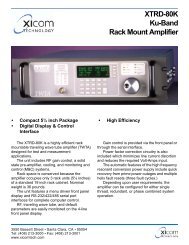
<strong>XT</strong>-<strong>400C</strong>/X/<strong>Ku</strong>-<strong>Band</strong><br />
<strong>Antenna</strong> <strong>Mount</strong><br />
<strong>Amplifiers</strong><br />
• 400 Watts C-<strong>Band</strong><br />
400 Watts X-<strong>Band</strong><br />
400 Watts <strong>Ku</strong>-<strong>Band</strong><br />
• No Shelter Required<br />
• Short Waveguide Run<br />
• Power Factor Corrected<br />
• High Efficiency Dual-Stage TWTs<br />
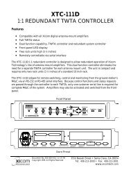
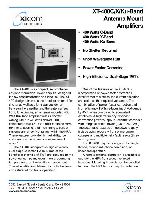
The <strong>XT</strong>-400 is a compact, self contained,<br />
antenna mountable power amplifier designed<br />
for low cost installation and long life. The <strong>XT</strong>-<br />
400 design eliminates the need for an amplifier<br />
shelter as well as a long waveguide run<br />
between the amplifier and the antenna feed<br />
horn; for example, an antenna mounted 400<br />
Watt <strong>Ku</strong>-<strong>Band</strong> amplifier with its shorter<br />
waveguide run will often deliver EIRP<br />
comparable to a 650 Watt rack mounted HPA.<br />
RF filters, cooling, and monitoring & control<br />
systems are all self contained within the HPA.<br />
These features provide high reliability, low<br />
maintenance costs, and low replacement<br />
costs.’<br />
The <strong>XT</strong>-400 incorporates high efficiency,<br />
dual-stage collector TWTs. Some of the<br />
benefits of this type of TWT are: reduced prime<br />
power consumption, lower internal operating<br />
temperatures, and reliability enhancement.<br />
These benefits are obtained for both the linear<br />
and saturated modes of operation.<br />
One of the features of the <strong>XT</strong>-400 is<br />
incorporation of power factor correction<br />
circuitry that minimizes line current distortion<br />
and reduces the required volt-amps. The<br />
combination of power factor correction and<br />
high efficiency TWTs reduces input Volt-Amps<br />
by 45% when compared to equivalent<br />
amplifiers. A high frequency resonant<br />
conversion power supply is used that accepts a<br />
wide range of prime power (100 to 260 VAC).<br />
The automatic features of the power supply<br />
include quick recovery from prime power<br />
outages and multiple helix fault resets (three<br />
fault cycles).<br />
The <strong>XT</strong>-400 may be configured for single<br />
thread, redundant, phase combined, or<br />
linearized operation.<br />
A remote external controller is available to<br />
operate the HPA from a user selected<br />
locations. <strong>Mount</strong>ing brackets can be supplied<br />
to mount the HPA to most popular antennas.<br />
3550 Bassett Street • Santa Clara, CA • 95054<br />
Tel: (408) 213-3000 • Fax: (408) 213-3001<br />
www.xicomtech.com
PERFORMANCE SPECIFICATIONS<br />
Parameter <strong>XT</strong>-<strong>400C</strong>, C-<strong>Band</strong> <strong>XT</strong>-400X, X-<strong>Band</strong> <strong>XT</strong>-400K, <strong>Ku</strong>-<strong>Band</strong><br />
FREQUENCY RANGE<br />
Extended Frequency Coverage<br />
5.850 to 6.425 GHz<br />
(5.85 to 6.725 GHz)<br />
7.90 to 8.40 GHz 13.75 to 14.5GHz<br />
(112.75 to 14.50 GHz)<br />
OUTPUT POWER<br />
Traveling Wave Tube<br />
Rated Power @ Amplifier Flange<br />
GAIN<br />
Large Signal, minimum<br />
Small Signal, minimum<br />
Maximum SSG Variation Over:<br />
Any Narrow <strong>Band</strong><br />
Full <strong>Band</strong><br />
Slope, maximum<br />
Stability, 24 Hr maximum<br />
Stability, Temperature<br />
GAIN CONTROL<br />
400 Watts<br />
350 Watts<br />
47 dB<br />
52 dB<br />
1.0 dB per 40 MHz<br />
2.5 dB<br />
± 0.04 dB/MHz<br />
± 0.25 dB<br />
400 Watts<br />
350 Watts<br />
47 dB<br />
52 dB<br />
1.0 dB per 40 MHz<br />
3.0 dB<br />
± 0.04 dB/MHz<br />
± 0.25 dB<br />
± 1.0 dB maximum over temperature range at any frequency<br />
20 dB<br />
400 Watts<br />
350 Watts<br />
47 dB<br />
52 dB<br />
1.0 dB per 80 MHz<br />
2.5 dB/500 MHz<br />
± 0.04 dB/MHz<br />
± 0.25 dB<br />
INTERMODULATION<br />
with two equal signals<br />
- 18 dBc maximum with two equal carriers at<br />
4 dB total power backoff from rated output<br />
HARMONIC OUTPUT, maximum - 60 dBc - 60 dBc - 60 dBc<br />
AM/PM CONVERSION, maximum<br />
2.5 deg/dB at 3 dB below rated output power<br />
NOISE POWER, maximum<br />
Transmit <strong>Band</strong><br />
- 70 dBW/4 kHz<br />
- 70 dBW/4 kHz<br />
- 70 dBW/4 kHz<br />
Receive <strong>Band</strong><br />
- 150 dBW/4 kHz<br />
3.7 to 4.2 GHz<br />
- 70 dBW/4 kHz<br />
7.25 to 7.75 GHz<br />
- 150 dBW/4 kHz<br />
10.95 to 12.75 GHz<br />
GROUP DELAY, maximum<br />
<strong>Band</strong>width<br />
Linear<br />
Parabolic<br />
Ripple<br />
Any 40 MHz<br />
± 0.01 nS/MHz<br />
± 0.005 nS/MHz 2<br />
0.5 nS/Pk-Pk<br />
Any 40 MHz<br />
± 0.01 nS/MHz<br />
± 0.005 nS/MHz 2<br />
0.5 nS/Pk-Pk<br />
Any 80 MHz<br />
± 0.01 nS/MHz<br />
± 0.005 nS/MHz 2<br />
0.5 nS/Pk-Pk<br />
RESIDUAL AM NOISE, maximum<br />
- 50 dBc to 10 kHz<br />
- 20 (1.5 + logf) dBc 10 to 500 kHz<br />
- 85 dBc above 500 kHz<br />
PHASE NOISE, maximum<br />
10 dB below IESS phase noise profile<br />
VSWR<br />
Input, maximum<br />
Output, maximum<br />
1.3:1<br />
1.3:1<br />
1.3:1<br />
1.3:1<br />
1.3:1<br />
1.3:1<br />
<strong>XT</strong>-<strong>400C</strong>/X/<strong>Ku</strong>
PRIME POWER<br />
OPTIONS<br />
100-260 VAC Detected RF<br />
47 to 63 Hz, single phase<br />
Remote External Controller<br />
XXX VA Typical<br />
Preamplifiers<br />
0.95 Minimum Prime Power Factor<br />
Gain Control<br />
Serial or Discrete Interface<br />
Extended Frequency Coverage<br />
1:1, 1:2, 1:N Redundancy<br />
Variable Phase Combined<br />
Integrated Linearizers<br />
ENVIRONMENT<br />
NONOPERATING TEMPERATURE RANGE<br />
OPERATING TEMPERATURE RANGE<br />
HUMIDITY<br />
ALTITUDE<br />
SHOCK AND VIBRATION<br />
COOLING<br />
-50° C to + 70° C<br />
-40° C to +50° C<br />
Up to 100% Condensing<br />
10,000 feet MSL maximum<br />
Normal Transportation<br />
Forced Air<br />
INTERFACE<br />
TYPE<br />
FUNCTION<br />
CONTROLS Power ON HV ON Fault Reset<br />
Heater Standby<br />
Note: heater Standby reduces the TWT heater voltage for situations where the high<br />
voltage is off for extended periods.<br />
MONITORS — DIGITAL Helix Current Latched Fault High Voltage ON Heater Standby (FTD)<br />
Helix Current/Arc Fault Summary Fault Standby<br />
High Voltage Fault<br />
Fan Fault<br />
MONITORS — ANALOG Cathode Voltage (1000:1 V/V) Helix Current (2 mA/V) TWT Temperature<br />
RF output Power (Optional) +15 VDC (100 MA max) +24 VDC (100 MA max)<br />
<strong>XT</strong>-<strong>400C</strong>/X/<strong>Ku</strong> High Power<br />
<strong>Amplifiers</strong>
Block Diagram<br />
Outline Drawing<br />
Document # 805-1105-001 11/17/2004<br />
<strong>XT</strong>-<strong>400C</strong>/X/<strong>Ku</strong> REV 2<br />
© 2004<br />
Note: Technical specifications are subject to change<br />
without notice. Please contact Xicom Technology before<br />
using this information for system design.<br />
3550 Bassett Street • Santa Clara, CA • 95054<br />
Tel: (408) 213-3000 • Fax: (408) 213-3001<br />
www.xicomtech.com