

Hydraulic separator - Caleffi
Hydraulic separator - Caleffi
Hydraulic separator - Caleffi

You also want an ePaper? Increase the reach of your titles
YUMPU automatically turns print PDFs into web optimized ePapers that Google loves.
<strong>Hydraulic</strong> <strong>separator</strong><br />
548 series<br />
01076/06 GB<br />
Replaces 01076/05 GB<br />
Product range<br />
548 series Threaded hydraulic <strong>separator</strong> with pre-formed insulation sizes 1”, 1 1/4”, and 1 1/2” F with union<br />
548 series Flanged hydraulic <strong>separator</strong> with pre-formed insulation sizes DN 50, DN 65, DN 80, DN 100, DN 125 and DN 150<br />
Technical specifications<br />
cert. n° 0003<br />
ISO 9001<br />
CALEFFI<br />
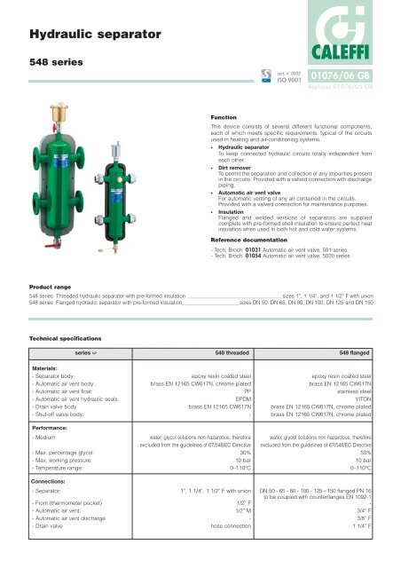
Function<br />
This device consists of several different functional components,<br />
each of which meets specific requirements, typical of the circuits<br />
used in heating and air-conditioning systems.<br />
· <strong>Hydraulic</strong> <strong>separator</strong><br />
To keep connected hydraulic circuits totally independent from<br />
each other.<br />
· Dirt remover<br />
To permit the separation and collection of any impurities present<br />
in the circuits. Provided with a valved connection with discharge<br />
piping.<br />
· Automatic air vent valve<br />
For automatic venting of any air contained in the circuits.<br />
Provided with a valved connection for maintenance purposes.<br />
· Insulation<br />
Flanged and welded versions of <strong>separator</strong>s are supplied<br />
complete with pre-formed shell insulation to ensure perfect heat<br />
insulation when used in both hot and cold water systems.<br />
Reference documentation<br />
- Tech. Broch. 01031 Automatic air vent valve, 501 series<br />
- Tech. Broch. 01054 Automatic air vent valve, 5020 series<br />
series ➫ 548 threaded 548 flanged<br />
Materials:<br />
- Separator body: epoxy resin coated steel epoxy resin coated steel<br />
- Automatic air vent body: brass EN 12165 CW617N, chrome plated brass EN 12165 CW617N<br />
- Automatic air vent float: PP stainless steel<br />
- Automatic air vent hydraulic seals: EPDM VITON<br />
- Drain valve body brass EN 12165 CW617N brass EN 12165 CW617N, chrome plated<br />
- Shut-off valve body: - brass EN 12165 CW617N, chrome plated<br />
Performance:<br />
- Medium water, glycol solutions non hazardous, therefore water, glycol solutions non hazardous, therefore<br />
excluded from the guidelines of 67/548/EC Directive excluded from the guidelines of 67/548/EC Directive<br />
- Max. percentage glycol: 30% 50%<br />
- Max. working pressure: 10 bar 10 bar<br />
- Temperature range: 0–110°C 0–110°C<br />
Connections:<br />
- Separator: 1”, 1 1/4”, 1 1/2” F with union DN 50 - 65 - 80 - 100 - 125 - 150 flanged PN 16<br />
to be coupled with counterflanges EN 1092-1<br />
- Front (thermometer pocket) 1/2” F -<br />
- Automatic air vent: 1/2” M 3/4” F<br />
- Automatic air vent discharge - 3/8” F<br />
- Drain valve hose connection 1 1/4” F
Technical specifications of insulation for threaded and<br />
flanged versions DN 125 and DN 150<br />
Internal part<br />
- Material: closed cell expanded PE-X<br />
- Thickness: - threaded 20 mm<br />
- flanged 60 mm<br />
- Density: - internal part: 30 kg/m3 - external part: 50 kg/m3 (threaded), 80 kg/m3 (flanged)<br />
- Thermal conductivity (ISO 2581): - 0°C: 0,038 W/(m·K)<br />
- Coefficient of resistance to the<br />
- 40°C: 0,045 W/(m·K)<br />
diffusion of water vapour (DIN 52615): > 1.300<br />
- Temperature range: 0–100°C<br />
- Reaction to fire (DIN 4102):<br />
External cover (for flanged versions DN 125 and DN 150)<br />
class B2<br />
- Material: embossed aluminium<br />
- Thickness: 0,70 mm<br />
- Reaction to fire (DIN 4102): class 1<br />
Technical specifications of insulation for flanged versions<br />
from DN 50 to DN 100<br />
Internal part<br />
- Material: rigid closed cell expanded polyurethane foam<br />
- Thickness: 60 mm<br />
- Density: 45 kg/m3 - Thermal conductivity (ISO 2581): 0,023 W/(m·K)<br />
- Temperature range:<br />
External cover<br />
0 –105°C<br />
- Material: embossed aluminium<br />
- Thickness: 0,7 mm<br />
- Reaction to fire (DIN 4102):<br />
Head covers<br />
class 1<br />
- Heat moulded material: PS<br />
Operating principle<br />
When a single system contains a primary production circuit, with its<br />
own pump, and a secondary user circuit, with one or more<br />
distribution pumps, operating conditions may arise in the system<br />
whereby the pumps interact, creating abnormal variations in circuit<br />
flow rates and pressures.<br />
The hydraulic <strong>separator</strong> creates a zone with a low pressure loss,<br />
which enables the primary and secondary circuits connected to it to<br />
be hydraulically independent of each other; the flow in one circuit<br />
does not create a flow in the other if the pressure loss in the<br />
common section is negligible.<br />
In this case, the flow rate in the respective circuits depends<br />
exclusively on the flow rate characteristics of the pumps, preventing<br />
reciprocal influence caused by connection in series.<br />
Therefore, using a device with these characteristics means that the<br />
flow in the secondary circuit only circulates when the relevant pump<br />
is on, permitting the system to meet the specific load requirements<br />
Dimensions<br />
When the secondary pump is off, there is no circulation in the<br />
secondary circuit; the whole flow rate produced by the primary<br />
pump is by-passed through the <strong>separator</strong>.<br />
With the hydraulic <strong>separator</strong>, it is thus possible to have a production<br />
circuit with a constant flow rate and a distribution circuit with a<br />
variable flow rate; these operating conditions are typical of modern<br />
heating and<br />
air-conditioning<br />
systems.<br />
Gp Gs<br />
at that time. Three possible hydraulical balance situations are shown below.<br />
Primary Secondary<br />
Gp Gs<br />
Primary Secondary<br />
Code A B C D E Weight (kg)<br />
548006 1" 225 195 220 204 2,7<br />
548007 1 1/4” 248 225 240 214 3,8<br />
548008 1 1/2” 282 235 260 224 5,7<br />
Size<br />
Volume (l)<br />
Gp Gs<br />
Code A B C D E F Weight (kg)<br />
548052 DN 50 1 1/4" 341 330 398 350 33<br />
548062 DN 65 1 1/4" 341 330 398 350 36<br />
548082 DN 80 1 1/4" 389 450 440 466 49<br />
548102 DN 100 1 1/4" 389 450 440 470 53<br />
548122 DN 125 1 1/4" 374 560 499 635 100<br />
548152 DN 150 1 1/4" 374 560 499 635 105<br />
primary secondary<br />
Primary Secondary<br />
Gp Gs<br />
Gprimary = Gsecondary Gprimary > Gsecondary Gprimary < Gsecondary<br />
D E<br />
A<br />
C<br />
A<br />
1”<br />
1,7<br />
Tmax 120°C Tmax 105°C<br />
Pmax 10 bar Pmax 10 bar<br />
B<br />
1 1/4”<br />
2,6<br />
1 1/2”<br />
4,8<br />
DN 50<br />
15<br />
DN 65<br />
15<br />
C D E<br />
A<br />
A<br />
DN 80<br />
30<br />
SEPARATORE IDRAULICO<br />
Serie 548<br />
Tmax 120°C Tmax 105°C<br />
Pmax 10 bar Pmax 10 bar<br />
B<br />
F<br />
DN 100<br />
30<br />
DN 125<br />
85<br />
DN 150<br />
88
Construction details<br />
Isolating the air vent valve<br />
In flanged <strong>separator</strong>s, the air vent is<br />
isolated manually, using a ball valve. In<br />
threaded <strong>separator</strong>s, however, the air<br />
vent body is automatically isolated by the<br />
built-in valve, which closes when the air<br />
vent body is removed.<br />
Dirt removing element<br />
A vital function of the hydraulic <strong>separator</strong><br />
is carried out by the dirt removing<br />
element inside the device. This makes it<br />
possible to separate and collect any<br />
impurities which may be present in the<br />
system.<br />
These impurities are removed by means<br />
of the drain valve, which can be<br />
connected to a discharge pipe, placed<br />
at the bottom of the <strong>separator</strong>.<br />
Insulation<br />
Flanged versions <strong>separator</strong>s up to DN 100 are available complete<br />
with the insulation made of a shell in expanded polyurethane foam<br />
coated with an aluminium layer. For threaded and flanged versions<br />
DN 125 and DN 150, insulation is made of a pre-formed shell in<br />
closed cell expanded PE-X.<br />
This insulation ensures not only perfect heat insulation but also the<br />
tightness required to prevent atmospheric water vapour from<br />
entering the unit. For these reasons, this type of insulation can also<br />
be used in cooling water circuits, as it prevents the formation of<br />
condensate on the surface of the valve body.<br />
<strong>Hydraulic</strong> characteristics<br />
The hydraulic <strong>separator</strong> should be sized according to the maximum<br />
flow rate value at the inlet. The selected design value must be the<br />
greatest between the primary circuit and the secondary circuit.<br />
Size Flow rate m 3 /h<br />
1” 2,5<br />
1 1/4” 4<br />
1 1/2” 6<br />
Size Flow rate m 3 /h<br />
DN 50 9<br />
DN 65 18<br />
DN 80 28<br />
DN 100 56<br />
DN 125 75<br />
DN 150 110
Application diagram<br />
Shut-off valve<br />
Check valve<br />
Three-way mixing valve<br />
Clock<br />
Temperature controller<br />
Pressure gauge<br />
SPECIFICATION SUMMARIES<br />
548 series<br />
<strong>Hydraulic</strong> <strong>separator</strong>. Connections 1” F (from 1” to 1 1/2”) with union. Front connection 1/2" F (thermometer pocket). Epoxy<br />
resin coated steel body. Medium: water, glycol solutions non hazardous, therefore excluded from the guidelines of<br />
67/548/EC Directive. Maximum percentage of glycol: 30%. Maximum working pressure: 10 bar. Temperature range:<br />
0–110°C.<br />
Supplied with:<br />
- Automatic air vent valve. 1/2” M connection. Brass body, chrome plated. PP float. EPDM hydraulic seals.<br />
- Drain valve. Hose connection. Brass body.<br />
- Hot pre-formed shell insulation in closed cell expanded PE-X. Temperature range: 0–100°C.<br />
548 series<br />
<strong>Hydraulic</strong> <strong>separator</strong>. Flanged connections DN 50 (from DN 50 to DN 150) PN 16, to be coupled with counterflanges EN 1092-1.<br />
Epoxy resin coated steel body. Medium: water, glycol solutions non hazardous, therefore excluded from the guidelines of<br />
67/548/EC Directive. Maximum percentage of glycol: 50%. Maximum working pressure: 10 bar.<br />
Temperature range: 0–110°C.<br />
Supplied with:<br />
- Automatic air vent valve. 3/4" F connection. 3/8” F discharge connection. Brass body. Stainless steel float. VITON hydraulic<br />
seals.<br />
- Drain valve. 1 1/4" F connection. Brass body, chrome plated.<br />
- Rigid closed cell expanded polyurethane foam shell insulation to DN 100 (closed cell expanded PE-X for DN 125 and DN 150).<br />
External embossed aluminium cover. Temperature range: 0–105°C (0–100°C for DN 125 and DN 150).<br />
We reserve the right to change our products and their relevant technical data, contained in this publication, at any time and without prior notice.<br />
CALEFFI<br />
CALEFFI S.P.A. · I · 28010 FONTANETO D’AGOGNA (NO) · S.R. 229, N.25 · TEL.INT. +39 0322 8491 R.A. · FAX +39 0322 863723<br />
· Http://www.caleffi.com · E-mail: info@caleffi.it ·


