R&S News 161 - Rohde & Schwarz
R&S News 161 - Rohde & Schwarz
R&S News 161 - Rohde & Schwarz

You also want an ePaper? Increase the reach of your titles
YUMPU automatically turns print PDFs into web optimized ePapers that Google loves.
<strong>News</strong> from <strong>Rohde</strong> & <strong>Schwarz</strong><br />
TV picture quality<br />
Objective measurement method<br />
Digital terrestrial video broadcasting<br />
Measurements to DVB-T standard<br />
TETRA mobile radio<br />
Signalling tests<br />
1999/I<br />
<strong>161</strong>
Number <strong>161</strong> 1999/I Volume 39<br />
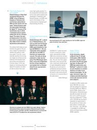
Digital video broadcasting (DVB) requires test<br />
methods that evaluate the picture signal itself<br />
and also consider perception by the human eye.<br />
<strong>Rohde</strong> & <strong>Schwarz</strong> together with the technical<br />
university of Braunschweig developed a realtime<br />
method for objective quality assessment of DCTcoded<br />
picture sequences (see final article on<br />
page 41). Photo 43 284<br />
Articles<br />
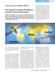
Josef Handl TV Test Transmitter SFQ Model 20<br />
TV via antenna: digitally fit ...................................................4<br />
Detlef Willam<br />
Thomas Rösner<br />
Peter Ludwig; Frank Körber<br />
TETRA Protocol Test System TS1240<br />
Type-approval tests of TETRA mobile radios ...................................7<br />
Digital Radiocommunication Tester CMD80<br />
CDMA, AMPS and IS136 measurements with one unit.......................10<br />
Digital Radiocommunication Test Set CRTx-DUO<br />
Test platform for HSCSD and multicarrier applications .......................13<br />
Software<br />
Thomas A. Kneidel; Peter Maurer PC, teletype and radio team up .............................................15<br />
Klaus-Dieter Tiepermann; Fit for the next millenium – W-CDMA signals with<br />
Andreas Pauly Signal Generator SMIQ and Software WinIQSIM ...........................16<br />
Application notes<br />
Frank Bergmann; Klaus Hesse Secure communication with ComSaveBox ....................................18<br />
Dr Anselm Fabig Use of R&S components for Inmarsat-E signal generation at navtec ...........20<br />
Damien Corti<br />
Volker Wimmer<br />
Hubert Kerscher; Karsten Friedrich<br />
Use of Measurement Decoder DVMD for quality control<br />
by Swiss broadcaster ........................................................22<br />
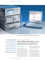
High-power and multicarrier tests with Base-Station Test System TS8510.......24<br />
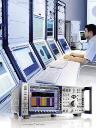
Theodor Fokken Portable, mobile or stationary radiomonitoring –<br />
<strong>Rohde</strong> & <strong>Schwarz</strong> has the ideal receiver every time ..........................25<br />
New functions added to A bis control software for<br />
Radiocommunication Testers CMD54/57 ....................................27<br />
2 <strong>News</strong> from <strong>Rohde</strong> & <strong>Schwarz</strong> Number <strong>161</strong> (1999/I)
Refresher topic<br />
Dr Hans-Christoph Höring<br />
Probability of intercept for frequency hop signals<br />
using search receivers (II)....................................................29<br />
Thomas Reichel<br />
Panorama<br />
Mobile power measurement with NRT sensor<br />
and PC Card Adapter NRT-Z4 ..............................................32<br />
Peter Maurer; Gerd Müller CECOM tests products from <strong>Rohde</strong> & <strong>Schwarz</strong> ..............................33<br />
Thomas Ehrhardt<br />
Simulation of channel noise and nonlinear amplifier distortion<br />
with Signal Generator SMIQ ................................................34<br />
Hans-Joachim Mann; ACS100 test systems for calibration of<br />
Gerhard Keßler R&S test and measurement equipment worldwide ...........................36<br />
Regular features<br />
Sigmar Grunwald Test hint: Determination of bit error ratio in DVB ...............................6<br />
Reference: Picturesque promotion............................................12<br />
Patent: Determination of cable length and/or jitter margin<br />
of data transmission paths...................................................28<br />
Information in print .........................................................37<br />
<strong>News</strong>grams ................................................................38<br />
Press comments .............................................................40<br />
Alexander Wörner; Harald Ibl Final article: Picture quality measurements for digital TV .....................41<br />
The European TETRA standard for professional<br />
mobile radio provides excellent transmission<br />
quality and frequency economy. To ensure errorfree<br />
communication, however, the terminal equipment<br />
must have unimpaired signalling capability.<br />
To test this, <strong>Rohde</strong> & <strong>Schwarz</strong> developed TETRA<br />
Protocol Test System TS1240 (see page 7).<br />
Imprint<br />
Published by ROHDE & SCHWARZ GmbH & Co. KG Mühldorfstraße 15 D - 81671 München<br />
Telephone (0 89) 41 29-0 · international (+49 89) 41 29-0 · Editors: H. Wegener and G. Sönnichsen<br />
(German) · English translation: Dept. 5CL4 · Photos: S. Huber · Artwork: S. v. Hösslin · Circulation<br />
95 000 six times a year · ISSN 0028-9108 · Supply free of charge · State company or position ·<br />
Printed in the Federal Republic of Germany by peschke druck, München · Reproduction of extracts<br />
permitted if source is stated and copy sent to R & S München<br />
<strong>News</strong> from <strong>Rohde</strong> & <strong>Schwarz</strong><br />
Number <strong>161</strong> (1999/I)<br />
3
Articles<br />
TV Test Transmitter SFQ Model 20<br />
TV via antenna: digitally fit<br />
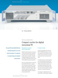
TV Test Transmitter SFQ is the solution for testing all digital TV receivers in development,<br />
production, quality assurance and service. Its speciality is that it can<br />
work as a test transmitter for established standards and adapt very fast to any<br />
newly introduced ones. The new SFQ model 20 is suitable for all measurement<br />
tasks of terrestrial TV in line with DVB-T standard.<br />
high-quality reception will be possible<br />
not only in buildings but also in the<br />
open without a special antenna and<br />
with mobile receivers. The present<br />
transmission network is being renewed,<br />
so transmit frequencies can be used<br />
more economically. The solution to all<br />
of this is complex coding, highly efficient<br />
error correction, OFDM (orthogonal<br />
frequency division multiplex) coding<br />
and emission via a single-frequency<br />
network.<br />
FIG 1 Model 20 of TV Test Transmitter SFQ is<br />
specially designed for DVB-T. Photo 45 592/2<br />
The change from analog to digital<br />
TV transmission is in full swing. New<br />
services like cable (DVB-C) and satellite<br />
(DVB-S) are already transmitting in digital.<br />
And terrestrial TV, the television of<br />
the first hour, is now also going digital.<br />
The standard [1] has been adopted,<br />
pilot field trials are in progress in many<br />
European countries and a nationwide<br />
broadcast network is already starting<br />
up in Great Britain. The reliability<br />
requirements of the new type of transmission<br />
and expectations are much<br />
higher than for cable and satellite. The<br />
purpose of terrestrial TV is providing<br />
basic coverage for the public at large.<br />
Compared to cable and satellite, the<br />
transmitting conditions are much more<br />
difficult, being influenced by weather,<br />
multipath propagation through landscape<br />
features as well as by other<br />
electronic radio services. Nevertheless,<br />
Data<br />
Clock<br />
FIG 2<br />
Baseband<br />
input module<br />
Inner<br />
interleaver<br />
SYNC1 inverter<br />
dispersal<br />
Mapping<br />
Reed-Solomon<br />
coder<br />
TV Test Transmitter SFQ model 20<br />
(FIG 1) is the right signal source for<br />
the whole range of measurement tasks.<br />
It provides all necessary signals in<br />
excellent quality. For special requirements<br />
the user can vary almost any<br />
parameter. Errors can be simulated and<br />
interference superimposed to mirror<br />
real transmission conditions.<br />
Outer error correction<br />
Frame<br />
adapter<br />
Outer<br />
interleaver<br />
OFDM<br />
coding<br />
Block diagram of DVB-T coder (blue: modules identical for satellite system)<br />
Convolutional<br />
coder,<br />
puncturing<br />
Inner error correction<br />
Guard<br />
interval<br />
I<br />
Q<br />
4 <strong>News</strong> from <strong>Rohde</strong> & <strong>Schwarz</strong> Number <strong>161</strong> (1999/I)
Articles<br />
Function<br />
SFQ generates a DVB-T signal fully<br />
compatible with ETS 300 744 in all<br />
its functions; the following parameters<br />
can be set:<br />
• bandwidth 6 MHz, 7 MHz and<br />
8 MHz with any intermediate values,<br />
• QPSK, 16QAM or 64QAM modulation,<br />
• code rate 1/2, 2/3, 3/4, 5/6,<br />
7/8,<br />
• guard interval 1/4, 1/8, 1/16,<br />
1/32,<br />
• COFDM with 2k or 8k mode,<br />
• optional hierarchical coding.<br />
FIG 3<br />
Menu of SFQ: DVB-T status display<br />
noise power makes it possible to<br />
determine BER characteristics for DVB-T<br />
receivers for example.<br />
The input signal to SFQ is the MPEG2-<br />
coded signal. After deriving the synchronizing<br />
information, the signal is<br />
taken to the scrambler where it is linked<br />
to a PRBS sequence for energy dispersal.<br />
The following stages are the same<br />
as for DVB-S: Reed-Solomon error<br />
correction, interleaver, convolutional<br />
encoder and puncturing (FIG 2). The<br />
rest of signal processing is DVB-T-specific.<br />
Due to the more unfavourable conditions<br />
of terrestrial propagation the<br />
signal is made to pass through further<br />
transmission correction stages: an inner<br />
bit interleaver (nearest to the antenna)<br />
and a symbol interleaver. Mapping is<br />
performed according to the selected<br />
QPSK, 16QAM or 64QAM coding.<br />
After insertion of the pilot and TPS<br />
(transmission parameter signalling)<br />
carriers in the frame adapter, digital<br />
data are changed to the time domain<br />
by an inverse fast Fourier transform,<br />
to a 1705 (2k) or 6817 (8k) carrier<br />
depending on the selected mode.<br />
Finally the guard interval is inserted.<br />
The further procedure is the same as for<br />
DVB-C/S: I/Q modulator, RF converter<br />
and lastly the attenuator for setting output<br />
level.<br />
Simulation features<br />
Functional tests with ideal signals are<br />
necessary but not very helpful for<br />
simulating a real situation. Errors and<br />
reception problems have to be simulated<br />
to define specifications and for<br />
functional testing under faulty conditions<br />
and at the operation limits. SFQ,<br />
designed as a stress generator, offers<br />
many features for such purposes. The<br />
I/Q modulation enables I and Q to<br />
be interchanged, which corresponds to<br />
a sideband switchover. The residual<br />
carrier can be set, the orthogonality<br />
between I and Q (I/Q phase) modified<br />
and the amplitude of I and Q (I/Q<br />
imbalance) varied.<br />
The modulation can be switched off<br />
for all carriers but also for individual<br />
carrier groups. The carriers are still<br />
available but not modulated. This can<br />
be done separately for the data, pilot<br />
and TPS carriers. Not just the modulation,<br />
the carriers too can be switched<br />
off individually or in groups. The coder<br />
permits deactivation of operationspecific<br />
functions such as scrambler<br />
(energy dispersal), Reed-Solomon error<br />
correction, convolutional, bit and symbol<br />
interleavers. In this way errors<br />
can be generated and reproduced<br />
individually to investigate whether bit<br />
errors have been corrected by the errorcontrol<br />
circuit or missing bits correctly<br />
replaced by the interleaver function.<br />
General transmission problems can be<br />
examined in addition to the separately<br />
selectable erroneous settings. An internal<br />
noise source allows poor receiving<br />
conditions to be simulated in a reproducible<br />
way. The precise setting of the<br />
The optional fading simulator is a big<br />
innovation. It serves for simulating<br />
reception by mobile receivers or in an<br />
unfavourable environment with a large<br />
number of reflections. The different<br />
paths of the fading simulator can also<br />
be used to simulate a single-frequency<br />
network.<br />
Applications<br />
The wide frequency range of SFQ from<br />
0.3 MHz to 3.3 GHz enables tests to<br />
be performed beyond frequency limits<br />
and at any intermediate frequencies.<br />
The large level range from –6 dBm<br />
to –99 dBm permits testing of sensitive<br />
modules beside providing sufficient<br />
level for in-service measurements. At<br />
the input interface it is possible to select<br />
between SPI (synchronous parallel interface)<br />
with LVDS (low-voltage differential<br />
signalling) and ASI (asynchronous<br />
serial interface). The following internal<br />
substitution signals are available: Null<br />
TS Packet, PRBS sequence or PRBS<br />
packets [2]. Of course, the well-proven<br />
features of SFQ model 10 [3] and<br />
of DVB-T Modulator SDB-M [4] were<br />
retained: user-friendly operation, messages<br />
for anomalous settings or operating<br />
states, status menu (FIG 3), online<br />
help, IEC/IEEE bus and RS-232-C interface<br />
as well as firmware updates from<br />
a PC. The modular concept, which<br />
allows retrofitting for DVB-C/S, is a<br />
platform for future standards and<br />
coding.<br />
<strong>News</strong> from <strong>Rohde</strong> & <strong>Schwarz</strong><br />
Number <strong>161</strong> (1999/I)<br />
5
Articles<br />
.<br />
With its flexible DVB-T test signals, TV<br />
Test Transmitter SFQ model 20 offers all<br />
the features needed in development,<br />
acceptance, quality assurance and<br />
servicing both for manufacturers of receivers<br />
of every kind and for operators<br />
of transmitters and receiving installations.<br />
Josef Handl<br />
REFERENCES<br />
[1] Lauterjung, J.: DVB-T, the new terrestrial TV<br />
standard. <strong>News</strong> from <strong>Rohde</strong> & <strong>Schwarz</strong><br />
(1997) No. 155, pp 31–32<br />
[2] Schmidt, P.: Optional input interface for TV<br />
Test Transmitter SFQ. <strong>News</strong> from <strong>Rohde</strong> &<br />
<strong>Schwarz</strong> (1997) No. 156, pp 34–35<br />
[3] Kretschmer, E.; Zimmermann, F.-J.: TV Test<br />
Transmitter SFQ – Digital test signals for<br />
the television future. <strong>News</strong> from <strong>Rohde</strong> &<br />
<strong>Schwarz</strong> (1997) No. 153, pp 14–16<br />
[4] Wießmeier, R.: DVB-T Modulator SDB-M –<br />
Start into digital terrestrial TV. <strong>News</strong> from<br />
<strong>Rohde</strong> & <strong>Schwarz</strong> (1997) No. 156, pp<br />
19–21<br />
Condensed data of TV Test Transmitter SFQ Model 20 for DVB-T<br />
Frequency range<br />
0.3 MHz to 3.3 GHz<br />
Level range<br />
–6 dBm to –99 dBm<br />
Bandwidths<br />
6/ 7/8 MHz (settable intermediate values)<br />
Inputs for MPEG2<br />
LVDS, ASI (option)<br />
FFT mode<br />
2k and 8k<br />
Modulation<br />
QPSK, 16QAM, 64QAM<br />
Guard interval 1/4, 1/8, 1/16, 1/32<br />
Inner code rate 1/2, 2/3, 3/4, 5/6, 7/8<br />
Carrier modification<br />
switchable carrier and modulation<br />
Error simulation<br />
carrier suppression, I/Q imbalance, phase error<br />
Special functions<br />
switchable: scrambler, Reed-Solomon coder,<br />
inner interleaver, bit and symbol interleaver<br />
Options<br />
hierarchical coding, noise superimposition,<br />
fading simulation, DVB-C and DVB-S<br />
Reader service card <strong>161</strong>/01<br />
Test hint<br />
Determination of bit error ratio in DVB<br />
The following questions are salient when assessing<br />
the quality of a DVB (digital video broadcasting)<br />
system: How high is the available margin of a<br />
DVB transmission? Up to what C/N ratio can a settop<br />
box still demodulate and decode DVB signals?<br />
The answers are obtained through deliberate<br />
deterioration of the C/N ratio by superimposing<br />
white noise on the DVB signal. Appropriate conversion<br />
produces the bit error ratio (BER) as a<br />
function of the C/N ratio for QPSK modulation<br />
and all QAM modes.<br />
Due to the steepness of the BER versus C/N curve<br />
at BER values
Articles<br />
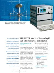
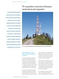
TETRA Protocol Test System TS1240<br />
Type-approval tests of TETRA<br />
mobile radios<br />
During the past year, TETRA has been firmly establishing itself to take over<br />
from the analog MPT1327 standard in wireless communication. About 25 projects<br />
are presently running in Europe and overseas. Any application based on analog<br />
systems is a potential market for TETRA. To ensure reliable communication –<br />
particularly for police, fire brigades and emergency services – not only RF<br />
parameters but also signalling procedures have to be tested in type approval of<br />
the transceivers, and this is where TETRA Protocol Test System TS1240 comes in.<br />
The breakthrough has finally been made<br />
– that would be the right description for<br />
the present status of TETRA (terrestrial<br />
trunked radio). Field trials like those in<br />
Denmark or the Schengen three-nation<br />
field trial have yielded positive results,<br />
while others (eg Berlin/Brandenburg<br />
police) are still in progress. High speech<br />
quality and data transmission at maximized<br />
frequency economy are clear<br />
advantages over other standards. Technically<br />
superior functions such as PDO<br />
(packet data optimized – for pure data<br />
transmission) or DMO (direct mode<br />
operation – direct connection between<br />
mobiles without a base station) are<br />
waiting to be introduced. On top of<br />
this, competition between manufacturers<br />
of terminal equipment has meanwhile<br />
brought about acceptable prices for<br />
mobile and base stations.<br />
To qualify for operation, terminal equipment<br />
has to pass the type-approval test<br />
to TBR35 (technical basis for regulation),<br />
which consists of two parts. In the<br />
first part RF parameters are tested with<br />
the aid of the <strong>Rohde</strong> & <strong>Schwarz</strong> TETRA<br />
Simulator TS8940 [1], and in the<br />
second part signalling procedures (of<br />
the protocol) are checked with TETRA<br />
Protocol Test System TS1240 (FIG 1).<br />
FIG 1 TETRA Protocol Test System TS1240 tests signalling procedures of TETRA mobiles in development and production. Photo 43 144/2<br />
<strong>News</strong> from <strong>Rohde</strong> & <strong>Schwarz</strong><br />
Number <strong>161</strong> (1999/I)<br />
7
Articles<br />
LLME<br />
Stack 1 Stack 0<br />
...<br />
Shortcut<br />
...<br />
...<br />
Block 0<br />
L3<br />
L2<br />
L1<br />
Beam<br />
FIG 2<br />
TETRA protocol<br />
concept: block,<br />
stack, layer (L1, L2,<br />
L3) and beam<br />
900 MHz is planned. Other features<br />
of TETRA are:<br />
• high spectral efficiency,<br />
• 25 kHz channel spacing with four<br />
timeslots per physical channel<br />
(TDMA),<br />
• π/4 DQPSK modulation (symbol<br />
rate 18 ksym/s),<br />
• voice and data transmission possible,<br />
• simplex, semi-duplex and duplex<br />
operation supported,<br />
• encryption (air interface, end-toend).<br />
Description of protocol tester<br />
TETRA status and<br />
specifications<br />
Details of TETRA status [2]:<br />
Phase 1 (completed in the first half of<br />
1997) defines network and air interface<br />
requirements as well as security<br />
requirements for PDO and V&D (voice<br />
plus data), plus standards and requirements<br />
for conformance tests at the air<br />
interface and stage one of the supplementary<br />
services.<br />
of V&D test suites and a test of the V&D<br />
and PDO air interfaces.<br />
TETRA operates in the frequency band<br />
380 to 440 MHz; an extension to<br />
TETRA Protocol Test System TS1240<br />
consists of the universal Protocol Test<br />
Unit PTW30 and Digital Radiocommunication<br />
Tester CMD91. The central<br />
unit PTW30 is based on a controller<br />
with hardware enhancements, ie a DSP<br />
card and an I/Q interface card. Radio-<br />
Phase 2 (completed in the second half<br />
of 1997) describes the air interface of<br />
the DMO and the SDL (specification<br />
description language) model, validation<br />
and test suites for edition 1 of TBR35,<br />
voice codec requirements and testing<br />
as well as three security algorithms.<br />
Phase 3 (shortly to be completed) defines<br />
the SDL model, validation and test<br />
suites for DMO and the SDL model as<br />
well as the validation for PDO and the<br />
second and third stages of the supplementary<br />
services, for the TETRA SIM<br />
card, the intersystem interface (ISI) for<br />
individual call and mobility management,<br />
edition 2 of TBR35, and the PSTN<br />
gateway.<br />
Phase 4 (in progress) defines the completion<br />
of the ISI group call and short<br />
data service, ISDN gateway, updates<br />
FIG 3<br />
Test System TS1240<br />
offers tools like<br />
PCO (top) and<br />
MSC for analysis<br />
of test results.<br />
8 <strong>News</strong> from <strong>Rohde</strong> & <strong>Schwarz</strong> Number <strong>161</strong> (1999/I)
Articles<br />
communication Tester CMD91 serves<br />
as an RF output stage in the transmit<br />
and receive directions. Data exchange<br />
between PTW30 and CMD91 is in the<br />
form of digital I/Q data, while device<br />
settings are serially transmitted.<br />
Syntax check<br />
.gr .mp .c .h .make<br />
.o<br />
TTCN Editor<br />
TTCN Compiler<br />
C Compiler<br />
.exe<br />
All functions required for the protocol<br />
test of TETRA terminal equipment are<br />
implemented in the test system software:<br />
System specific part<br />
LT interface<br />
Simulator Library<br />
Protocol Library<br />
Because of the time-critical requirements<br />
of the TETRA protocol stack, a<br />
realtime operating system – LynxOS –<br />
is used. This Unix derivative is compatible<br />
with Posix and SystemV.<br />
The TETRA protocol engine contains<br />
all processes, data and interfaces<br />
required to control the TETRA protocol<br />
stack (FIG 2). One possible operating<br />
mode of TS1240 is simulation of a<br />
base station for testing a TETRA mobile<br />
phone after registration via the air interface.<br />
Another operating mode allows<br />
the setting up of a direct connection<br />
from a higher layer (eg via Ethernet) to<br />
an external controller, where a single<br />
layer has been started as a DUT<br />
(virtual type approval).<br />
A modern graphical user interface<br />
(GUI) is implemented offering the usual<br />
windows. The simulation manager<br />
enables selection and setting of the<br />
desired simulation mode. PCO (point<br />
of control and observation between<br />
logical layers) and MSC (message<br />
sequence chart representing data transmitted<br />
between TS1240 and DUT in<br />
decoded form across all layers) are<br />
among the means available for result<br />
analysis. FIG 3 illustrates the interaction<br />
between the modules.<br />
FIG 4 Two-stage implementation of ETSI test<br />
cases in TETRA Test System TS1240<br />
The test cases defined by ETSI (European<br />
Telecommunications Standards<br />
Institute) are in a language particularly<br />
suitable for protocol tests: TTCN (tree<br />
and tabular combined notation, in the<br />
case of TETRA with ASN.1 notation).<br />
This language allows fast and convenient<br />
conversion of test cases into<br />
executables. This coding is implemented<br />
in Test System TS1240 in two steps<br />
(FIG 4). First the supplied TTCN compiler<br />
translates the code into C language.<br />
Secondly, C is translated into executables<br />
using system libraries. With the<br />
aid of a test case selector, one or more<br />
test cases can be conveniently selected<br />
and started via the graphical interface,<br />
the verdicts being clearly displayed in<br />
tabular form. Trace files generated<br />
during program run permit detailed<br />
analysis down to command level.<br />
Tests not covered by ETSI test cases can<br />
be implemented by creating their own<br />
scenario. For this TS1240 hardware<br />
and software are available via function<br />
calls (open programming platform). A<br />
scenario executor permits the programs<br />
to be executed in realtime or line by<br />
line.<br />
TETRA Protocol Test System TS1240 is<br />
ideal for the development and testing of<br />
TETRA signalling procedures and able<br />
to translate TTCN test cases published<br />
by ETSI into executables. TS1240 features<br />
all attributes of a modern protocol<br />
tester, following in the steps of a long<br />
tradition of <strong>Rohde</strong> & <strong>Schwarz</strong> protocol<br />
testers for mobile radio standards.<br />
Detlef Willam<br />
REFERENCES<br />
[1] Schneider, H.-J.; Tiwald, W.: TETRA Test<br />
Systems TS8940 – Type-approval tests of<br />
TETRA base and mobile stations to TBR35.<br />
<strong>News</strong> from <strong>Rohde</strong> & <strong>Schwarz</strong> (1997)<br />
No. 153, pp 4–6<br />
[2] Brian, O.: The road ahead – The future<br />
for the TETRA Project. TETRA International<br />
Conference, London (1998)<br />
Features of TETRA Protocol Test System TS1240<br />
Implementation to standard of TETRA protocol stack (layer 1 and 2)<br />
TTCN test cases executable to TBR35<br />
All protocol layers implemented per software<br />
TETRA air interface implemented<br />
Open platform concept for programming of scenarios<br />
Graphical user interface<br />
Reader service card <strong>161</strong>/04<br />
<strong>News</strong> from <strong>Rohde</strong> & <strong>Schwarz</strong><br />
Number <strong>161</strong> (1999/I)<br />
9
Articles<br />
Digital Radiocommunication Tester CMD80<br />
CDMA, AMPS and IS136<br />
measurements with one unit<br />
The successful Digital Radiocommunication Tester CMD80 has evolved into a<br />
multimode mobile radio tester: It now masters D-AMPS according to IS136 along<br />
with CDMA and AMPS, making it an indispensable tool in the development,<br />
production and service of mobile radio equipment worldwide.<br />
<strong>Rohde</strong> & <strong>Schwarz</strong> offers such a solution<br />
in CMD80 (FIG 1) for full implementation<br />
of D-AMPS test technology<br />
both with and without signalling. The<br />
capability of performing mobile radio<br />
measurements according to the three<br />
standards with just one instrument is<br />
of decisive importance not only in<br />
development and service but also, and<br />
in particular, in production, where<br />
flexible use of mobile radio testers is<br />
required. Due to the rapid growth of<br />
mobile radio in South America and the<br />
Far East, there is huge potential for<br />
a multimode/multiband compact tester<br />
such as CMD80 in these regions too.<br />
The hardware platform of CMD80<br />
offers a continuous frequency range<br />
from 800 to 2200 MHz and the measurements<br />
are carried out by means of a<br />
digital signal processor. This flexible<br />
concept makes it possible to upgrade a<br />
CDMA/AMPS dual-mode/dual-band<br />
CMD80 [1 to 3] to a multimode/dualband<br />
tester with a minimum of hardware<br />
and software, which can be<br />
installed straightforward and fast by<br />
a service technician.<br />
The various D-AMPS measurements can<br />
be performed either as a module test (ie<br />
without call setup with the mobile telephone)<br />
or with signalling (manual test).<br />
Both the US cellular band (800 MHz)<br />
and the PCS band (1900 MHz) are<br />
covered. The user interface and<br />
the IEC/IEEE-bus control comply<br />
with the well-proven concept of CDMA<br />
and AMPS measurements in CDM80,<br />
enabling operation without special<br />
knowledge of the different networks.<br />
FIG 1 Digital Radiocommunication Tester<br />
CMD80, the compact tester for multimode/dualband<br />
mobiles Photo 43 263<br />
In the US, digital networks operating<br />
with TDMA (time division multiple access)<br />
– D-AMPS – are gaining in importance<br />
alongside mobile radio networks<br />
based on the analog AMPS (advanced<br />
mobile phone system) and the digital<br />
CDMA (code division multiple access)<br />
standard. In most cases, dual-mode<br />
mobile telephones with CDMA/AMPS<br />
function (IS95 standard) or D-AMPS/<br />
AMPS function (IS136 standard) are<br />
offered, often as dual-band phones<br />
for the 800 MHz (US cellular) and<br />
1900 MHz (PCS) frequency bands.<br />
The consequence of this is that a mobile<br />
radio tester is needed that combines<br />
all three standards in both frequency<br />
bands in a single unit.<br />
Measurement standard IS136 defines<br />
an external interface to control mobile<br />
telephones for testing. This common<br />
interface enables checking the different<br />
DUT modules without call setup, so the<br />
manufacturing process can run at a<br />
much faster rate. A bit error rate measurement<br />
can even be carried out, ie the<br />
receive path of the mobile can also be<br />
tested without signalling. The following<br />
measurements are possible in the<br />
D-AMPS module test with CMD80:<br />
10 <strong>News</strong> from <strong>Rohde</strong> & <strong>Schwarz</strong> Number <strong>161</strong> (1999/I)
Articles<br />
In transmitter testing a detailed modulation<br />
analysis of the signal received<br />
from the mobile station is performed at<br />
the power level and frequency defined<br />
by the user. The test signal is recorded,<br />
synchronized and demodulated. An<br />
ideal reference signal, which is compared<br />
with the DUT signal, can be<br />
generated from these data. The error<br />
vector magnitude (magnitude of the<br />
vectorial error function versus time), the<br />
magnitude error (amplitude error) and<br />
the phase error arising during modulation<br />
can be derived and represented<br />
graphically as a time function versus<br />
the emitted burst. These parameters<br />
plus frequency error, origin offset<br />
(carrier crosstalk) and I/Q imbalance<br />
(measure of unequal gain in the I or Q<br />
path of the transmitter modulator) are<br />
statistically evaluated and displayed.<br />
The amplitude droop is also determined<br />
to indicate the level difference<br />
between the start and the end of a<br />
TDMA burst.<br />
What is particularly important for<br />
TDMA systems is measurement of<br />
power versus time, compared to<br />
a user-configurable template. Finally,<br />
an adjacent-channel power measurement<br />
(ACP) can be performed. This<br />
examines spectral effects due to switching<br />
the burst on and off and effects<br />
due to modulation, which may disturb<br />
transmission in adjacent channels. All<br />
six adjacent/alternate channels are<br />
evaluated at the same time and represented<br />
in a bar diagram (FIG 2). As an<br />
alternative, the power curve within an<br />
adjacent channel can be examined in<br />
the time domain.<br />
For receiver testing the mobile station<br />
is set to a loopback mode via an external<br />
controller by means of a command<br />
defined in the D-AMPS standard.<br />
CMD80 then sends a test signal at a<br />
level that can be set in a wide range,<br />
and which contains a suitable, known<br />
bit sequence. The mobile telephone<br />
can synchronize to this sequence and<br />
return it to CMD80 after demodulation.<br />
This reflected signal (errorfree transmission<br />
on the uplink from the mobile<br />
to the base station can be assumed) is<br />
demodulated to bit level in CMD80,<br />
compared with the known bits of the<br />
original signal and the bit error rate<br />
then calculated. The sensitivity of the<br />
mobile station can be determined in this<br />
way (FIG 3).<br />
FIG 2<br />
ACP measurement<br />
with Digital Radiocommunication<br />
Tester<br />
CMD80 in D-AMPS<br />
module test<br />
FIG 3<br />
Bit error rate measurement<br />
on receive<br />
section of mobile<br />
with CMD80<br />
The manual test mode with call setup<br />
to the mobile telephone is used<br />
to perform menu-guided operational<br />
checks as required in particular in<br />
final production testing and in service.<br />
In this test mode the mobile first registers<br />
in the base station, which is simulated<br />
by CMD80. After that a call<br />
with voice loopback can be set up by<br />
CMD80 or the telephone to be tested.<br />
The audio data recorded by the<br />
mobile’s microphone are buffered<br />
in CMD80 and reflected to the tested<br />
mobile station after a 2 s delay. In this<br />
way the speech quality of the DUT can<br />
be checked.<br />
A call is set up by CMD80 or the<br />
mobile to perform the measurements.<br />
In addition to the parameters that can<br />
already be examined in the module<br />
test, a time-alignment measurement<br />
is offered in this mode. CMD80<br />
signals to the mobile telephone the<br />
time delay, if any, of the mobile’s<br />
burst signal with respect to the<br />
reference clock in the network and<br />
measures this time offset. This function<br />
is important with TDMA systems for<br />
propagation delay compensation in<br />
distant base stations. CMD80 can<br />
also check SMS (short message service)<br />
transfer to D-AMPS mobile telephones<br />
(base station to mobile station).<br />
This verifies the capability of a<br />
mobile to receive and display userdefinable<br />
text messages up to a length<br />
of 256 bytes.<br />
Another feature of CMD80 is simulation<br />
of mobile assisted handoff as<br />
defined by IS136. When instructed<br />
by CMD80, the mobile telephone<br />
examines signal quality in different<br />
RF channels and reports the results<br />
to the base station to support the<br />
handoff procedure. Implicit handoffs<br />
within the standard, ie handoff to<br />
another digital traffic channel (a new<br />
channel number) or changeover to<br />
another timeslot on the same TDMA<br />
frequency, can be performed as well<br />
as handoffs from and to AMPS. This is<br />
decisive for testing multimode mobile<br />
telephones.<br />
<strong>News</strong> from <strong>Rohde</strong> & <strong>Schwarz</strong><br />
Number <strong>161</strong> (1999/I)<br />
11
Articles<br />
Based on its new TDMA measurement<br />
capability, CMD80 with its high-speed<br />
IEC/IEEE-bus operation, clear and uniform<br />
operating concept for AMPS,<br />
CDMA and D-AMPS and compact design<br />
offers a future-oriented approach<br />
and thus optimum prerequisites for use<br />
in development, service and production.<br />
Thomas Rösner<br />
REFERENCES<br />
[1] Maucksch, T.: CMD80: measurements for<br />
CDMA and AMPS mobiles. <strong>News</strong> from<br />
<strong>Rohde</strong> & <strong>Schwarz</strong> (1997) No. 154,<br />
pp 22–23<br />
[2] Mittermaier, W.: Digital Radiocommunication<br />
Testers CMD65 and CMD80 – Multiband<br />
and multimode testers for mobile-radio<br />
telephones. <strong>News</strong> from <strong>Rohde</strong> & <strong>Schwarz</strong><br />
(1997) No. 155, pp 6–8<br />
[3] Maucksch, T.: From dual-mode to multimode<br />
radiocommunication tester – IS136 standard<br />
now implemented in CMD80. <strong>News</strong> from<br />
<strong>Rohde</strong> & <strong>Schwarz</strong> (1997) No. 156, p 33<br />
Key features of Digital Radiocommunication Tester CMD80<br />
Multimode/dual-band mobile radio tester for production, development, service<br />
High measurement speed, high flexibility, simple operation<br />
Networks and frequency bands<br />
US cellular (800 MHz)<br />
CDMA(IS95), AMPS/N-AMPS (IS95)<br />
D-AMPS/NADC (IS136, IS54)<br />
US PCS (1900 MHz)<br />
CDMA (UB-IS95, J-STD008)<br />
D-AMPS/NADC (IS136, IS54)<br />
Japan cellular<br />
CDMA (T53, IS95), N-TACS/J-TACS<br />
China cellular<br />
CDMA (IS95), E-TACS/TACS<br />
Korea PCS (1800 MHz)<br />
CDMA (J-STD008, UB-IS95)<br />
Reader service card <strong>161</strong>/05<br />
Reference<br />
Picturesque promotion<br />
For once DVB-T transmitters<br />
and modulators<br />
and DVB-T test equipment<br />
from <strong>Rohde</strong> &<br />
<strong>Schwarz</strong> have been<br />
chosen for a totally<br />
different job from<br />
their normal one.<br />
Utilizing the full stock<br />
of photographic skills,<br />
they were put on<br />
the front page of this<br />
brochure to publicize<br />
reference books on<br />
the topic “Radio, Television,<br />
Multimedia”<br />
from the German publisher<br />
Hüthig Fachverlage<br />
of Heidelberg.<br />
At Hüthig specialized qualifications are considered<br />
the all-important basis of successful careers as well<br />
as of innovation in business, engineering, research<br />
and science. Hüthig was set up as a family<br />
enterprise in 1925. Today some 70 journals, over<br />
2500 book titles, 120 loose-leaf collections and<br />
a growing number of electronic products and services<br />
demonstrate the publisher’s extraordinary<br />
commitment to the transfer of know-how.<br />
The DVB-T components from <strong>Rohde</strong> & <strong>Schwarz</strong>,<br />
which are already being used in several projects,<br />
show the same innovative and future-oriented spirit.<br />
A major pilot project was started in the Munich<br />
area to test digital video broadcasting via terrestrial<br />
networks (DVB-T). The network used for the<br />
purpose is a single-frequency network with one<br />
transmitter atop Munich’s Olympic tower and two<br />
others in the suburbs of Freimann and Ismaning.<br />
The project is intended to verify the DVB-T system<br />
in operation and makes use of <strong>Rohde</strong> & <strong>Schwarz</strong><br />
DVB-T transmitters and modulators as well as T&M<br />
equipment.<br />
DVB-T components from <strong>Rohde</strong> & <strong>Schwarz</strong> play<br />
a key role in Europe’s first digital terrestrial TV<br />
network (in Britain). <strong>Rohde</strong> & <strong>Schwarz</strong> was contracted<br />
to supply DVB-T TV transmitters of the<br />
NV500 family with rms power of up to 4 kW,<br />
CODFM Modulators SDB-M, which are fully compatible<br />
with ETS300744, and MPEG2 Measurement<br />
Decoders DVMD for realtime analysis.<br />
Sö<br />
12 <strong>News</strong> from <strong>Rohde</strong> & <strong>Schwarz</strong> Number <strong>161</strong> (1999/I)
Articles<br />
Digital Radiocommunication Test Set CRTx-DUO<br />
Test platform for HSCSD<br />
and multicarrier applications<br />
Mobile radio manufacturers frequently have to perform critical four-channel<br />
handover or cell selection/reselection tests during the development of a new<br />
model. They also require measurement equipment for testing new data services<br />
such as high-speed circuit-switched data (HSCSD) and general packet radio<br />
services (GPRS), which make use of more than one active timeslot at a time.<br />
CRTx-DUO, a combination of two Radio Test Sets CRTS, CRTP or CRTC, which can<br />
be operated as stand-alones again at any time, is a fully fledged four-channel<br />
tester ideal for these testing scenarios.<br />
separate physical channels with one<br />
timeslot each or a combined channel<br />
of two timeslots to be configured with<br />
a CRTx and its two RF channels.<br />
CRTx-DUO, a combination of two units,<br />
offers four channels and is therefore<br />
ideal for this application (FIG 1).<br />
For multislot applications, up to three<br />
channels can be grouped to form<br />
a channel of three timeslots. One<br />
possible configuration is a C0 carrier<br />
(BCCH) and a traffic channel (uplink<br />
and downlink) of three timeslots. This<br />
combination also supports frequency<br />
hopping of course.<br />
Test specification GSM Rec. 11.10<br />
prescribes all test cases to be performed<br />
for the type approval of mobile<br />
radios. The vast majority of them are<br />
signalling tests and can be performed<br />
with two RF channels. The stand-alone<br />
testers offered for these applications by<br />
<strong>Rohde</strong> & <strong>Schwarz</strong> come from the CRTx<br />
family of Digital Radiocommunication<br />
Test Sets: CRTS (GSM900), CRTP<br />
(GSM900 and GSM1800) and CRTC<br />
(GSM900, GSM1800 and GSM1900)<br />
[1]. They are available with numerous<br />
software options covering all specified<br />
tests.<br />
and at least one traffic channel (TCH or<br />
data) have to be emulated, thus making<br />
four channels. New services like<br />
HSCSD and GPRS require several timeslots<br />
simultaneously for correct data<br />
transmission. A CRTx can emulate one<br />
timeslot per channel. This allows two<br />
For multislot layer 1 module tests it<br />
is even possible to emulate a channel<br />
of four timeslots, because in this case<br />
no C0 carrier is required. A typical<br />
example is the bit error rate test that is<br />
performed in the initial development<br />
stage of data services. This verifies<br />
whether the data received in a particular<br />
timeslot by the mobile phone are<br />
looped back in the correct timeslot.<br />
The type approval tests supported by<br />
the stand-alone units have without<br />
exception been accredited by test<br />
houses, thus making their use for type<br />
approval testing official. One reason<br />
why test houses are glad to resort to<br />
these <strong>Rohde</strong> & <strong>Schwarz</strong> solutions is<br />
that in this way they can keep their<br />
highly complex TS89xx systems [2] –<br />
exclusively supplied by <strong>Rohde</strong> &<br />
<strong>Schwarz</strong> worldwide – free for elaborate<br />
RF tests.<br />
However, more than one channel is<br />
required for cell selection/reselection<br />
and handover tests when examining<br />
the behaviour of mobile phones under<br />
typical conditions. For intercell handover<br />
tests, for instance, two network<br />
cells each with a C0 carrier (BCCH)<br />
FIG 1<br />
Multislot channel<br />
measurement<br />
of GSM mobile<br />
with DUO consisting<br />
of two Digital Radiocommunication<br />
Test<br />
Sets CRTC<br />
Photo 43 250
Articles<br />
Slave unit<br />
DSP<br />
Operating program<br />
Information control<br />
DSP<br />
CRTx-DUO may consist of any combination<br />
of CRTx units (FIG 2). The<br />
operating software of the DUO automatically<br />
recognizes the models used<br />
and addresses them accordingly. The<br />
largest number of possibilities is offered<br />
by a combination of two CRTC models.<br />
This dual setup even supports full<br />
multiband handover functions, for instance<br />
handover from a GSM900 to<br />
a GSM1900 traffic channel. What<br />
makes CRTx-DUO particularly attractive<br />
for the user is that it can easily be<br />
split up into two stand-alones whenever<br />
required. Like Type-Approval Test<br />
Systems TS89xx, CRTx-DUO is based<br />
on CRTx units, so it can be upgraded<br />
later to form a complete system. This<br />
may become necessary if requirements<br />
for RF accuracy are more stringent than<br />
those for the signalling tests normally<br />
carried out with CRTx-DUO. The DUO<br />
is thus an ideal upgrade or downgrade<br />
for the <strong>Rohde</strong> & <strong>Schwarz</strong> selection of<br />
GSM testers.<br />
Operating the DUO is almost the same<br />
as operating a single CRTx. Test scenarios<br />
written by the user can be<br />
programmed on the same, slightly<br />
expanded application platform that<br />
was recently added to the stand-alone<br />
tester. This platform is standard for<br />
all new applications and test cases for<br />
RS-232-C<br />
IEC/IEEE<br />
Sync<br />
10 MHz<br />
DSP<br />
to/from mobile phone<br />
CRTx and TS89xx systems. This means<br />
that customers familiar with the individual<br />
units will not require extra training.<br />
Applications and test cases written for<br />
the DUO platform will also run on a<br />
TS89xx system without modifications.<br />
Every test application or test case<br />
consists of a master program running<br />
on the master digital unit and a slave<br />
program on the slave digital unit.<br />
Both programs can exchange data via<br />
a communication link. This also gives<br />
the master program full remote control<br />
capability for the slave CRTx. The<br />
master therefore provides the user interface<br />
for the whole system. Normally the<br />
slave program only needs to perform<br />
the call establishment procedure with<br />
assignment to the master traffic channel.<br />
This allows it to be used for various<br />
tests without modifications, provided<br />
it is sufficiently configurable with parameters.<br />
A slave program of this kind<br />
is included in the master application<br />
of the DUO operating software<br />
CR02DUO. This means that no programming<br />
is required apart from modifying<br />
the master program for a new<br />
test. The actual programming is therefore<br />
very much the same as for a test<br />
with a single unit. Besides the functions<br />
mentioned above, the master-slave<br />
communication link is also capable of<br />
transmitting files in both directions.<br />
An intercell handover application and<br />
a simple program for configuring a<br />
C0 carrier channel and a channel of<br />
three timeslots are also supplied. They<br />
can serve as a basis for the user’s own<br />
programs. The package also includes<br />
a selftest that, together with a mobile<br />
phone, verifies the functioning of all<br />
essential signalling routines of the<br />
DUO. The software for the DUO platform<br />
is continuously being added to<br />
and updates are quite straightforward.<br />
Peter Ludwig; Frank Körber<br />
REFERENCES<br />
[1] Körber, F.; Steffen, R.: Digital Radiocommunication<br />
Test Set CRTC02 growing with<br />
standard GSM. <strong>News</strong> from <strong>Rohde</strong> &<br />
<strong>Schwarz</strong> (1997) No. 155, pp 30–31<br />
[2] Mellein, H.: Type approval of GSM900/<br />
GSM1800 multiband mobiles using System<br />
Simulator TS8915. <strong>News</strong> from <strong>Rohde</strong> &<br />
<strong>Schwarz</strong> (1998) No. 157, pp 28–29<br />
Condensed data of Digital Radiocommunication Test Set CRTx-DUO<br />
(functions not included in stand-alone CRTx)<br />
RF channels<br />
Test cases<br />
Master unit<br />
Digital unit<br />
Tx/Rx Tx/Rx Tx/Rx Tx/Rx<br />
FIG 2 Block diagram of Digital Radiocommunication<br />
Test Set DUO with two CRTx<br />
DSP<br />
Analog unit<br />
Application<br />
Operating program<br />
Information control<br />
DSP<br />
DSP<br />
Reader service card <strong>161</strong>/06<br />
four fully synchronized channels to GSM Rec.<br />
5.xx, three of which can be grouped to form<br />
a channel of three timeslots; the fourth channel<br />
emulates the C0 carrier (BCCH)<br />
HSCSD, intercell handover, intracell handover,<br />
cell selection/reselection<br />
four-channel layer 1 module test<br />
14 <strong>News</strong> from <strong>Rohde</strong> & <strong>Schwarz</strong> Number <strong>161</strong> (1999/I)
Software<br />
PC, teletype and radio team up<br />
Even though the combination of radio<br />
and teletype (RATT) is generally no<br />
longer regarded as a modern means of<br />
information exchange, it is often the<br />
only available basis for data transmission<br />
due to its widespread use.<br />
Whether onboard a ship or in an<br />
embassy, teletype is still frequently used<br />
for sending text messages by radio.<br />
Texts are normally written in the internationally<br />
defined format ACP-127<br />
(allied communication protocol). For<br />
transmission, the individual teletype<br />
characters are converted to 5-bit<br />
Baudot code. FSK (frequency-shift keying)<br />
is used to modulate the radio link.<br />
With data transmission rates between<br />
50 and 600 baud, FSK may be comparatively<br />
slow but it is very resistant to<br />
interference.<br />
PC<br />
workstation<br />
FIG 1<br />
LAN<br />
Software<br />
ACP-MHS<br />
HF Transceiver<br />
XK2000<br />
teletype unit at the other (FIG 1). With<br />
the aid of this program, texts can be<br />
generated on a PC, and the teletypewriter<br />
at the distant station prints them<br />
out on paper or as punched tape.<br />
Conversely, conventional teletype messages<br />
are intelligible to ACP-MHS<br />
stations, which store them as files. The<br />
user is thus able to replace the teletypewriter<br />
by a PC and the program DS150<br />
without losing teletype as a medium.<br />
DS150 also supports the administration<br />
and logging of all received and transmitted<br />
messages in log books (FIG 2).<br />
The program’s convenient user interface,<br />
the intuitive operating concept<br />
and a special mask-oriented editor simplify<br />
errorfree generation of teletype<br />
messages in line with strict ACP-127<br />
guidelines. Depending on the individ-<br />
HF Transceiver<br />
XK2000<br />
Radio data transmission with teletypewriter and ACP Message Handling System DS150<br />
Teletypewriter<br />
FIG 2 User interface of log book with various<br />
sorting criteria<br />
ACP-MHS Software DS150 does away<br />
with the restricted interoperability<br />
between teletype and other computerbased<br />
data services. Combined with<br />
the E-mail product PostMan DS100<br />
[1; 2], the software may also be used to<br />
attach ACP messages to E-mails for<br />
transmission on all types of networks.<br />
The other way round, DS150 can<br />
forward received E-mail messages to<br />
teletype subscribers.<br />
Thomas A. Kneidel; Peter Maurer<br />
The ACP-127 format, which also serves<br />
for automatic archiving, addressing,<br />
prioritizing and classification, requires<br />
the observance of strict formal guidelines<br />
and involves a great deal of effort,<br />
especially in the preparation of texts<br />
and handling of received messages. If<br />
large numbers of messages are to be<br />
received or transmitted, management<br />
tools that support the user are indispensable.<br />
A tool of this type is now offered<br />
by <strong>Rohde</strong> & <strong>Schwarz</strong> in the form<br />
of the software product ACP Message<br />
Handling System DS150 (ACP-MHS<br />
DS150). It runs under Windows NT<br />
and allows data exchange on a radio<br />
path between a PC at one end and a<br />
ual requirements, HF, VHF or UHF radio<br />
equipment may be used for transmitting<br />
the generated messages.<br />
Besides RATT operation, the software<br />
also allows automatic reception of<br />
broadcast messages. Messages received<br />
in this way are automatically<br />
analyzed and placed in receive queues<br />
according to priority. The messages<br />
can be sorted within the queues according<br />
to various criteria such as<br />
date time group (DTG) or station serial<br />
number (SSN). In contrast to the pointto-point<br />
links of RATT operation, no<br />
confirmation is issued for broadcast<br />
messages.<br />
REFERENCES<br />
[1] Kneidel, T.: When the PostMan rings on Internet.<br />
<strong>News</strong> from <strong>Rohde</strong> & <strong>Schwarz</strong> (1997)<br />
No. 153, pp 28–29<br />
[2] Kneidel, T.: PostMan on tour. <strong>News</strong> from<br />
<strong>Rohde</strong> & <strong>Schwarz</strong> (1998) No. 159, p 34<br />
Reader service card <strong>161</strong>/07<br />
<strong>News</strong> from <strong>Rohde</strong> & <strong>Schwarz</strong><br />
Number <strong>161</strong> (1999/I)<br />
15
Software<br />
Fit for the next millennium – W-CDMA signals<br />
with Signal Generator SMIQ and Software WinIQSIM<br />
There are two ways of upgrading<br />
Signal Generator SMIQ [1] to a source<br />
for W-CDMA (wideband code division<br />
multiple access) signals. One way<br />
involves using Modulation Generator<br />
AMIQ [2] to provide the necessary<br />
W-CDMA baseband signals for SMIQ.<br />
In this case the unit is operated<br />
via a convenient menu in Software<br />
WinIQSIM [3]. The other way is<br />
through W-CDMA option SMIQB43,<br />
which is now available and makes<br />
SMIQ a stand-alone W-CDMA source.<br />
The well-proven options Data Generator<br />
SMIQB10 and Modulation Coder<br />
SMIQB11 are used to generate the<br />
baseband signals.<br />
FIG 1 Downlink signal with 15 code channels;<br />
code domain power measurement with W-CDMA<br />
analyzer<br />
is very simple. A new operating menu<br />
for W-CDMA is obtained after upgrading<br />
SMIQ with new firmware and entering<br />
the supplied installation key. It is<br />
thus possible to cost-effectively upgrade<br />
all SMIQs equipped with the data generator<br />
and modulation coder options to<br />
a W-CDMA source. Both uplink and<br />
downlink signals can be generated, so<br />
manufacturers of mobile stations and<br />
base stations benefit equally from the<br />
new option. Up to 15 code channels<br />
can be switched on at the same time<br />
(FIG 1). This also applies to an uplink<br />
signal, since W-CDMA standards stipulate<br />
several active code channels for<br />
the mobile station (multicode transmission).<br />
An additional uplink mode of<br />
SMIQ permits multiplex operation for<br />
the I and Q components of the baseband<br />
signal as defined by the ARIB<br />
standard (FIG 2). SMIQ not only performs<br />
the spectral spreading of modulation<br />
data with orthogonal codes and<br />
long code in line with standards, it also<br />
provides the frame structure for the various<br />
physical channels such as perch,<br />
common control or dedicated physical<br />
channel. The data fields of channels<br />
can be filled with pseudo-random data<br />
sequences to test modules such as amplifiers.<br />
Advantageous for the receiver<br />
test is that the user can resort to freely<br />
programmable data lists to store channel-coded<br />
data sequences. All standard<br />
symbol rates between 16 ksym/s and<br />
1024 ksym/s are available at a<br />
chip rate of 4.096 Mchip/s. There are<br />
additional setting possibilities, for example<br />
for a time offset of modulation<br />
data, for selecting the spreading codes<br />
or for assigning a power control symbol.<br />
The user thus has a comprehensive<br />
set of tools for defining an individual<br />
test scenario. All associated SMIQ<br />
settings can of course be saved for<br />
later use.<br />
The high setting flexibility of W-CDMA<br />
option SMIQB43 is particularly important<br />
at a stage where the standardization<br />
and definition of test specifications<br />
are not yet finalized. The large number<br />
of possible settings along with excellent<br />
signal quality make SMIQ an ideal<br />
source for testing W-CDMA modules of<br />
every kind. For spectral regrowth measurements<br />
on power amplifiers, SMIQ is<br />
outstanding with an ACPR of –64 dBc.<br />
The quality of the output spectrum can<br />
be further improved through the use of<br />
ACP option SMIQB46 (adjacent channel<br />
power) [4]. With its clean spectrum<br />
and vector error of only 1.5 %, SMIQ<br />
is a reference source of the highest<br />
quality.<br />
The development of W-CDMA systems<br />
is already very advanced, especially in<br />
Japan. So both sources support signal<br />
generation in line with Japanese specifications,<br />
in particular the standard of<br />
the Association of Radio Industries and<br />
Businesses (ARIB) for a third-generation<br />
mobile radio system.<br />
DPDCH 1<br />
DPDCH 3<br />
DPDCH 2<br />
Short Code 1<br />
Short Code 2<br />
Short Code 1<br />
I<br />
Q<br />
Complex<br />
Spreading<br />
Baseband<br />
Filter<br />
I<br />
Q<br />
SMIQ has a good track record as<br />
an IS95 CDMA signal generator.<br />
Equipped with W-CDMA option<br />
SMIQB43 the generator can now<br />
deliver wideband CDMA signals at a<br />
keystroke. Installation of the software<br />
FIG 2<br />
Uplink signal<br />
generation to<br />
ARIB standard<br />
DPDCH 4<br />
DPDCH<br />
Short Code 2<br />
Short Code 0<br />
g<br />
Long Code<br />
16 <strong>News</strong> from <strong>Rohde</strong> & <strong>Schwarz</strong> Number <strong>161</strong> (1999/I)
Software<br />
FIG 3 User interface WinIQSIM; left: CCDF of<br />
W-CDMA downlink signal with 15 code channels<br />
and data offset; right: signal spectrum with<br />
ACP measurement<br />
from several base stations can be configured.<br />
This functionality is provided<br />
both on the downlink and the uplink<br />
and fulfills every requirement in the<br />
generation of highly complex signal<br />
scenarios.<br />
WinIQSIM not only generates W-CDMA<br />
signals but also signals to standard<br />
IS95 (A) in conjunction with the digital<br />
standard option AMIQK11. Up to<br />
eight complete base stations each with<br />
64 code channels can be simulated on<br />
the forward link and 16 mobile stations<br />
on the reverse link. The power of channels<br />
can be set separately as required.<br />
Thanks to its flexibility, the combination<br />
WinIQSIM, AMIQ and SMIQ is ready<br />
for the future, especially for multicarrier<br />
signals and standard proposals such as<br />
CDMA2000.<br />
Klaus-Dieter Tiepermann;<br />
Andreas Pauly<br />
In addition to generation of single-carrier<br />
and multicarrier signals and the versatile<br />
superimposition of impairments,<br />
the user-friendly I/Q Simulation Software<br />
WinQSIM offers the possibility of<br />
conveniently generating W-CDMA signals.<br />
The combination I/Q modulation<br />
source AMIQ plus WinIQSIM and<br />
SMIQ is virtually unsurpassed in terms<br />
of flexibility and diversity of functions.<br />
With its memory depth of 4 000 000<br />
samples per channel and a sampling<br />
rate of up to 100 MHz, AMIQ again<br />
fully demonstrates its capabilities.<br />
Chip rates for future extensions of the<br />
W-CDMA system are ready implemented<br />
(8.192 and 16.384 Mchip/s)<br />
in addition to 4.096 Mchip/s. The<br />
standard symbol rates of between<br />
16 ksym/s and 1024 ksym/s can be<br />
selected depending on chip rate. Of<br />
course, WinIQSIM generates the signal<br />
components for the various physical<br />
channels (1st and 2nd perch, common<br />
control and dedicated) in the standard<br />
frame structure that is clearly displayed<br />
on the user interface. Depending on<br />
chip rate up to 512 code channels are<br />
available at the same time. The power<br />
of the individual code channels, the<br />
short code and other parameters such<br />
as data, long code offset and power<br />
control symbols can be set for each<br />
channel. In this way a mixture of signals<br />
In addition to a variety of signal-specific<br />
functions, WinIQSIM offers some<br />
options that are very helpful for generating<br />
W-CDMA signals, especially for<br />
computation and display of the complementary<br />
cumulative distribution function<br />
(CCDF). The CCDF indicates the<br />
relative probability that the complex<br />
samples of the W-CDMA signal will<br />
exceed a certain level. Besides the crest<br />
factor, this function provides information<br />
on the distribution of samples in the<br />
I/Q domain, which is an indispensable<br />
tool in the development of amplifiers for<br />
example (FIG 3 left). The usual graphic<br />
modes such as the constellation diagram<br />
or signal spectrum for W-CDMA<br />
signal analysis are still available.<br />
Another new feature is measurement of<br />
adjacent-channel power (FIG 3 right).<br />
This function permits optimization of<br />
baseband filters with respect to adjacent-channel<br />
power already at the<br />
development stage or for the extension<br />
of communication standards. This kind<br />
of optimization is indispensable in the<br />
face of increasingly densely occupied<br />
frequency bands and the scarcity of<br />
frequencies. The comprehensive signal<br />
generation capabilities of WinIQSIM<br />
are rounded off by the context-sensitive<br />
online help, which displays detailed<br />
information at a mouse click for each<br />
window of the user interface. This is<br />
especially useful with complex communication<br />
standards like W-CDMA.<br />
REFERENCES<br />
[1] Tiepermann, K.-D.: Signal Generator SMIQ<br />
+ SMIQB42 – Multichannel signal source for<br />
CDMA. <strong>News</strong> from <strong>Rohde</strong> & <strong>Schwarz</strong><br />
(1997) No. 156, pp 13–15<br />
[2] Kernchen, W.; Tiepermann, K.-D.: I/Q Modulation<br />
Generator AMIQ – Convenient<br />
generation of complex I/Q signals. <strong>News</strong><br />
from <strong>Rohde</strong> & <strong>Schwarz</strong> (1998) No. 159,<br />
pp 10–12<br />
[3] Pauly, A.; Holzhammer, J.: I/Q Simulation<br />
Software WinIQSIM – New approaches in<br />
calculating complex I/Q signals <strong>News</strong><br />
from <strong>Rohde</strong> & <strong>Schwarz</strong> (1998) No. 159,<br />
pp 13–15<br />
[4] Klier, J.: ACP measurements for W-CDMA<br />
using Signal Generator SMIQ and Low ACP<br />
option. <strong>News</strong> from <strong>Rohde</strong> & <strong>Schwarz</strong> (1998)<br />
No. 160, pp 19–20<br />
Reader service card <strong>161</strong>/08<br />
<strong>News</strong> from <strong>Rohde</strong> & <strong>Schwarz</strong><br />
Number <strong>161</strong> (1999/I)<br />
17
Application notes<br />
Secure communication with ComSaveBox<br />
FIG 1<br />
ComSaveBox<br />
encrypts any<br />
modem link online.<br />
Photo 42 801<br />
Serial links are widely used to transmit<br />
information. The data are usually<br />
transmitted via modems and public telephone<br />
networks. But anyone can access<br />
these routes, so there are threats to<br />
confidentiality and integrity of data.<br />
Data can be intercepted, manipulated<br />
or retained, for example, without the<br />
sender or recipient noticing. Consequently<br />
sensitive data have to be suitably<br />
protected against such threats.<br />
The most efficient method is the use<br />
of cryptography, ie transformation of<br />
data so that no conclusions can be<br />
drawn about their contents. Furthermore,<br />
there are special mechanisms to<br />
protect transmitted information against<br />
unnoticed manipulation.<br />
ComSaveBox security system<br />
The small ComSaveBox (FIG 1) ensures<br />
confidentiality of data during their<br />
transfer via the serial interface of a data<br />
terminal, a PC for example. All data<br />
are automatically encrypted before<br />
they are sent out and decrypted when<br />
received, thus reliably protecting<br />
them against unauthorized access. The<br />
FEAL-16X algorithm used for encryption<br />
has been analyzed worldwide and is<br />
generally recognized. It has a code<br />
length of 128 bits and is an impenetrable<br />
barrier even for modern methods<br />
of cryptoanalysis. The design and development<br />
of such systems was based<br />
on German and European criteria for<br />
IT security. ComSaveBox supports an<br />
RS-232-C interface with rates from<br />
9600 to 115 200 baud and the usual<br />
standard protocol (8 bits, no parity bit,<br />
1 stop bit). The necessary hardware<br />
protocol (DTR/DSR or RTS/CTS) is fully<br />
transparent.<br />
The unit can be operated in encrypted<br />
and in open transmission mode. In encrypted<br />
mode the data sent from the<br />
data terminal to ComSaveBox are first<br />
encrypted and then forwarded to the<br />
data transmission equipment. Data received<br />
by the transmission equipment<br />
and transferred to ComSaveBox are<br />
decrypted and then passed to the<br />
data terminal. The code used for<br />
encryption and decryption is set by<br />
the communication partners prior to<br />
data transmission or by remote access<br />
through a configuration program. The<br />
user can choose between a temporary<br />
and a permanent code. A permanent<br />
code, which remains stored when<br />
ComSaveBox is switched off, is recommended<br />
for frequently used links,<br />
as for example to a company headquarters,<br />
and a temporary code for<br />
one-time links. ComSaveBox operates<br />
with full transparency in the open<br />
mode. Data transmission uses the customary<br />
software, eg terminal programs<br />
for access to mailboxes and connection<br />
to other computers and programs for<br />
accessing networks via a modem<br />
line (eg asynchronous communication<br />
server, NetWare Connect).<br />
Examples of application<br />
File transfer between mailbox<br />
and PC<br />
The mailbox of a company stores confidential<br />
data, and only authorized<br />
persons may access it. Password protection<br />
alone is not considered sufficient<br />
to prevent unauthorized access. The<br />
mailbox is installed on a computer that<br />
is fitted with a modem and receives<br />
incoming calls. In addition, data should<br />
be protected against unauthorized<br />
eavesdropping during transmission in<br />
the telephone network. To this end,<br />
the mailbox computer is fitted with<br />
ComSaveBox. All persons who are to<br />
have access to the mailbox also have<br />
ComSaveBox installed (FIG 2). For<br />
mailbox access a code is defined that<br />
only authorized persons are informed<br />
of. This enables connection to the mailbox<br />
and data exchange in encrypted<br />
form. Connections in plain text or with<br />
the incorrect code are automatically<br />
interrupted by ComSaveBox.<br />
Access to Novell network<br />
via modem<br />
Company employees are to be able to<br />
access the inhouse Novell network from<br />
their homes. For this a connect server<br />
18 <strong>News</strong> from <strong>Rohde</strong> & <strong>Schwarz</strong> Number <strong>161</strong> (1999/I)
Application notes<br />
with a modem and NetWare Connect<br />
software are installed. The NetWare<br />
password used as the sole means of<br />
protection is not regarded as sufficient<br />
to prevent unauthorized access. In<br />
addition to the password, data are to<br />
be protected by encryption during<br />
transmission in the telephone network.<br />
The connect server is fitted with<br />
ComSaveBox. All persons who are to<br />
have access to the network will also<br />
have ComSaveBox installed at their<br />
end and a code is arranged with them.<br />
Links with differently set operating<br />
modes (eg one ComSaveBox set to<br />
“Crypt”, the other to “Open”) or with<br />
an incorrect code are automatically<br />
interrupted by ComSaveBox.<br />
Transmission via RS-232-C interface<br />
without modem signals<br />
The data collected by a telemetry station<br />
are to be transmitted by radio to a<br />
stored even with ComSaveBox<br />
switched off. In this case no further configuration<br />
of the telemetry unit is required,<br />
ie a PC is not needed at the site.<br />
With the configured ComSaveBox<br />
installed at the telemetry station, an<br />
encrypted link can be set up when<br />
needed by means of the “Crypt“ key on<br />
the ComSaveBox at the central station.<br />
When the link is no longer required,<br />
the encrypted link is cleared down<br />
by pressing the “Crypt” key again. Of<br />
course, open links are possible any<br />
time using the “Open” key.<br />
Use of ISDN modem<br />
Users who frequently have to transmit<br />
large amounts of data cost-effectively<br />
will recognize the benefits of ISDN.<br />
ISDN modems present a number of<br />
advantages over plug-in PC cards, so<br />
their fields of application are constantly<br />
expanding. Installation, identification,<br />
available resources (interrupts) and<br />
problems with CAPI drivers make the<br />
use of plug-in PC cards less desirable.<br />
What is more, ISDN modems can<br />
easily be taken to another operating<br />
site, also in connection with laptops.<br />
The transmitted data are to be protected<br />
against unauthorized access.<br />
ComSaveBox is most suitable for this<br />
application, especially with its high<br />
communication speed of 115 kbaud.<br />
An ISDN modem (eg MicroLink ISDN/<br />
Tlpro from ELSA) is required for this purpose.<br />
ComSaveBox is inserted between<br />
the PC and the ISDN modem<br />
and initialized (setting of code and<br />
mode). If the called station has the<br />
same configuration, transmission is<br />
possible with a terminal program (eg<br />
Telix from ELSA). Transmission rates of<br />
up to 115 200 baud can be achieved<br />
with two B channels (channel trunking).<br />
Frank Bergmann; Klaus Hesse<br />
REFERENCES<br />
[1] Krieghoff, H.; Sörgel, D.: SIT – Security in<br />
Information Technology. <strong>News</strong> from <strong>Rohde</strong> &<br />
<strong>Schwarz</strong> (1997) No. 153, pp 41– 43<br />
[2] Bergmann, F.: Security for modem links with<br />
ComSaveBox. <strong>News</strong> from <strong>Rohde</strong> & <strong>Schwarz</strong><br />
(1997) No. 155, p 39<br />
Modem<br />
Modem<br />
Encrypted data<br />
FIG 2<br />
ComSaveBox<br />
encryption unit is<br />
inserted between<br />
data terminal (here<br />
PC) and data transmission<br />
equipment<br />
(here modem).<br />
central station. The radio equipment<br />
has an RS-232-C interface to send<br />
digital information, and this is to be<br />
encrypted against unauthorized access<br />
during transmission. ComSaveBox is<br />
inserted into the link between the data<br />
collection unit and the radio equipment<br />
of the station, and another one is required<br />
at the central station. Here the<br />
RS-232-C mode is set for the two boxes<br />
and also the code for the unit of the<br />
telemetry station, ie when a permanent<br />
code is to be used, which remains<br />
Reader service card <strong>161</strong>/09<br />
<strong>News</strong> from <strong>Rohde</strong> & <strong>Schwarz</strong><br />
Number <strong>161</strong> (1999/I)<br />
19
Application notes<br />
Use of R&S components for Inmarsat-E signal<br />
generation at navtec<br />
FIG 1 Test setup for generation of Inmarsat-E<br />
distress call data at Berlin-based company navtec<br />
Photo: Schäfer<br />
A new worldwide standard for transmitting<br />
and evaluating distress calls<br />
from ships and aircraft, Inmarsat-E, has<br />
established itself in the last few years.<br />
It is a system operating in conjunction<br />
with the four geostationary Inmarsat<br />
satellites. The standard was developed<br />
and formulated with the objective of<br />
ensuring reliable and unrestricted transmission<br />
of distress calls within the<br />
shortest possible time and for a large<br />
number of users. In contrast to LEO<br />
(low earth orbit) satellites, which can be<br />
received at a specific position on the<br />
earth only for a short time once every<br />
one to two hours, geostationary satellites<br />
guarantee reception and evaluation<br />
without any time restrictions. They<br />
also offer more channels, so they can<br />
serve a much larger number of users<br />
simultaneously.<br />
FIG 2 Block diagram of setup for Inmarsat-E<br />
trial emissions with Signal Generator SMIQ,<br />
Spectrum Analyzer FSEA and Waveform Generator<br />
ADS, all from <strong>Rohde</strong> & <strong>Schwarz</strong><br />
Controller<br />
ADS<br />
ROHDE & SCHWARZ<br />
IEC/IEEE bus<br />
Bit clock<br />
10 MHz reference<br />
In the past, only two LEO satellites<br />
(COSPAS/SARSAT) were available for<br />
the reception and evaluation of distress<br />
transmitters. The fixed frequency of<br />
121.5 MHz and localization based<br />
on measuring the Doppler shift when<br />
overflying the vessel in distress resulted<br />
in highly inaccurate position data.<br />
The situation improved somewhat<br />
when a second transmission frequency<br />
SMIQ<br />
Signal generation<br />
ROHDE & SCHWARZ<br />
Signal analysis<br />
FSEA<br />
Tx<br />
Rx<br />
20 <strong>News</strong> from <strong>Rohde</strong> & <strong>Schwarz</strong> Number <strong>161</strong> (1999/I)
Application notes<br />
(406.025 MHz), a more suitable form<br />
of modulation (PSK/TDMA) and transmitter<br />
identification were introduced.<br />
The numbers of false alarms were high<br />
because of the ease of triggering, but<br />
distress calls could all be allocated.<br />
Transmission techniques<br />
A major problem of using geostationary<br />
instead of LEO satellites is the great<br />
distance from the earth (36 000 km).<br />
To be able to use battery-powered portable<br />
units with low power consumption,<br />
the prescribed transmit power had to<br />
be reduced. This was only possible<br />
through a new approach in the selection<br />
of the transmission scheme and the<br />
modulation.<br />
ponents available at the time. Distress<br />
call data were simulated for emission<br />
via the Inmarsat transponders by a<br />
setup consisting of Signal Generator<br />
SMIQ, Waveform Generator ADS,<br />
Spectrum Analyzer FSEA, a PC<br />
with IEC/IEEE-bus card and software<br />
HP-VEE (FIGs 1 and 2).<br />
The key component of this setup was<br />
Signal Generator SMIQ, whose “list<br />
mode” was used to generate the emitted<br />
signals. The required data set was<br />
computed on a conventional PC and<br />
transmitted to SMIQ on an IEC/IEEE<br />
bus (FIG 3). Spectrum Analyzer FSEA<br />
not only provided the 10 MHz<br />
reference frequency but also served<br />
programmed on an IEC/IEEE bus. This<br />
makes SMIQ flexible for adaptation to<br />
measurement problems that are not<br />
covered by built-in standards.<br />
navtec coordinated the trial transmissions<br />
with Inmarsat headquarters in<br />
London. All receiving land earth<br />
stations (LES) in the range of the three<br />
visible satellites confirmed reception of<br />
the signals down to a transmit power<br />
of just 18 dBm.<br />
Dr Anselm Fabig (www.navtec.de)<br />
The Inmarsat-E system operates with<br />
carrier FSK (±120 Hz) and 667 channels<br />
(300 Hz spacing) at 1.645 GHz<br />
(uplink). The satellite itself has only<br />
a 200 kHz wide transponder at<br />
3.619 GHz (downlink). The signal<br />
emitted by a distress transmitter consists<br />
of a 100-bit telegram prefixed by a<br />
20-bit sync word and suffixed by a<br />
40-bit CRC sum. The telegram contains<br />
encoded information on identity, position<br />
and nature of distress.<br />
To ensure that the low-power signals<br />
(27 to 31 dBm) appear at the ground<br />
station receiver with sufficient energy<br />
after travelling such a long distance, the<br />
energy of successive emissions has to<br />
be summed. The telegram is therefore<br />
repeated for a duration of five minutes.<br />
The receiver knows the exact length of<br />
a telegram, so it can easily sum the<br />
signal and distinguish it from the noise.<br />
Furthermore, the FEC (forward error<br />
correction) checksum allows correction<br />
of up to five bit errors.<br />
Test system configuration<br />
FIG 3<br />
Screen shot of<br />
software for<br />
programming<br />
Signal Generator<br />
SMIQ at navtec<br />
For its initial trials to determine output<br />
power requirements, the correctness of<br />
bit pattern generation and antenna<br />
functionality, the company navtec<br />
computed a test signal offline, which<br />
was then generated using reliable comfor<br />
checking the FSK signal at a second<br />
antenna. The software for analyzing<br />
the FSEA data, also run on the PC, was<br />
a slightly modified version of software<br />
used in the lab. The final transmission<br />
signal was generated by an Amplifier<br />
Research output stage. A 0 dB antenna<br />
with clockwise circular polarization<br />
was used to radiate the signal.<br />
SMIQ is ideal in test setups such as<br />
these, because it generates signals<br />
with high accuracy and can easily be<br />
<strong>News</strong> from <strong>Rohde</strong> & <strong>Schwarz</strong><br />
Number <strong>161</strong> (1999/I)<br />
21
Application notes<br />
Use of Measurement Decoder DVMD<br />
for quality control by Swiss broadcaster<br />
Broadcasters are increasingly turning<br />
to digital technology for better management<br />
of resources and the spectrum.<br />
When a broadcaster today decides<br />
in favour of satellite transmission, this<br />
will be in line with DVB and MPEG2<br />
standards – at least in Europe. This<br />
means that the signal must be conditioned,<br />
compressed and multiplexed<br />
before it can be modulated and sent to<br />
FIG 1 Measurement Decoder DVMD for analysis<br />
of MPEG2 transport streams<br />
Photo 43 179/5<br />
the satellite. At this point the question of<br />
measurement and quality arises. Is the<br />
signal delivered to the satellite errorfree?<br />
Analog technology is no longer<br />
suitable for this purpose. In analog<br />
pictures interference like noise is visible<br />
immediately. In the case of signals sent<br />
to a satellite at 38 Mbit/s measurement<br />
is much more complicated. Digital technology<br />
can be deceptive because you<br />
suppose everything to be normal when<br />
you hear the sound or see the picture.<br />
Conventional monitoring is obviously<br />
insufficient. To determine whether<br />
everything is as it should be in an<br />
MPEG2 digital signal, you have to analyze<br />
the signal structure and examine<br />
the sections in which video and audio<br />
information is transported [1].<br />
Choice of instrument<br />
The MPEG2 standard and its principles<br />
are very complex, so it could take<br />
months to analyze and check the contents<br />
of an MPEG2 stream. The broadcaster,<br />
however, must guarantee errorfree<br />
signals throughout. Furthermore,<br />
after installation a DVB transmission<br />
system may be operated and monitored<br />
by staff who are not necessarily<br />
specialized in MPEG2. For these reasons<br />
the Swiss broadcaster SRG-SSR<br />
decided to use MPEG2 Measurement<br />
Decoder DVMD [2] as a realtime test<br />
instrument (FIG 1). It takes continuous<br />
analysis of the signals transferred to<br />
the Hot Bird 3 satellite to ensure correct<br />
operation of the equipment. This roundthe-clock<br />
analysis by means of DVMD<br />
actually enabled the supplier of the<br />
DVB-S system to improve it, since<br />
SRG-SSR was the first broadcaster to<br />
permanently analyze the signal, and<br />
thus equipment errors and instabilities<br />
could be detected. No compromise<br />
was made: the signal had to conform<br />
fully to MPEG2 standard.<br />
For an optimum grip on the origin of<br />
faults, SRG-SSR decided in favour of a<br />
measurement principle that ensures the<br />
following requirements are met:<br />
• The signal emitted must conform to<br />
the standard.<br />
• The signal received from the satellite<br />
and passed on to the viewers must<br />
be absolutely errorfree (1st and 2nd<br />
priority).<br />
FIG 2 shows the implementation, requiring<br />
two DVMDs. It ensures that<br />
the signals transmitted (output by the<br />
main multiplexer) and the signals<br />
received are conformal. In case of<br />
problems SRG-SSR can quickly deter-<br />
22 <strong>News</strong> from <strong>Rohde</strong> & <strong>Schwarz</strong> Number <strong>161</strong> (1999/I)
Application notes<br />
Multi-<br />
plexer<br />
(operation)<br />
Multi-<br />
plexer<br />
(standby)<br />
DVB system<br />
Set-top box<br />
PAT ok<br />
PMT ok<br />
Transmission monitoring<br />
MPEG2<br />
transport<br />
stream<br />
DVMD<br />
Set-top box<br />
Control room<br />
mine whether they are caused by the<br />
satellite, by poor reception or by the<br />
multiplexer itself, which may transmit<br />
signals already errored.<br />
Results after four months<br />
QPSK<br />
QPSK<br />
PAT ok<br />
PMT ok<br />
DVMD<br />
Reception monitoring<br />
Transmission<br />
FIG 2<br />
Block diagram of<br />
monitoring concept<br />
using two MPEG2<br />
Measurement<br />
Decoders DVMD<br />
determined and the programs were<br />
found to be really impaired. To detect<br />
the origin of the error, a more in-depth<br />
analysis was again necessary by the<br />
system supplier, who is also responsible<br />
for eliminating the problem.<br />
in front of DVMD to analyze errors of<br />
uncertain origin. To keep operating<br />
costs reasonable, a technician may<br />
only be called in case of a real alarm.<br />
At SRG-SSR alarm messages are output<br />
by a central system to which DVMD will<br />
also be connected and that will signal<br />
all errors lasting more than one minute<br />
(eg if a teletext PID fails).<br />
SRG-SSR’s objective is to ensure that all<br />
systems multiplexing its six television<br />
programs and the six radio programs<br />
of Radio Suisse International can be operated<br />
with a minimum of maintenance<br />
and repair. In view of the complexity of<br />
the systems, this will only be possible<br />
with the right working concept, and<br />
DVMD is an important part of it.<br />
Damien Corti (SRG-SSR General<br />
Management, Engineering &<br />
Information Technology)<br />
Within the first 24 hours DVMD had<br />
signalled numerous errors, and after<br />
further investigation two causes for<br />
the MPEG2 errors could be tracked<br />
down in the DVB systems and eliminated<br />
by the supplier through parameter<br />
modifications. The causes of sporadic<br />
errors were extremely difficult to trace<br />
however. In these cases in-depth analyses<br />
are required for troubleshooting.<br />
The error display of DVMD is clear<br />
and convenient. You merely select<br />
the parameter in question to find the<br />
error details. However, it is necessary<br />
to know exactly to what the error (eg<br />
Upper Dist) and PID (packet identification)<br />
of the errored element refer. For<br />
operation the PID number is sufficient<br />
since staff have a list of all important<br />
PIDs used in the programs. With the aid<br />
of DVMD, SRG-SSR detected errors in<br />
the broadcast programs. But most settop<br />
boxes received these programs<br />
without major problems, except in one<br />
case where interruptions were heard.<br />
DVMD indicated that the PCRs (program<br />
clock references) were out of<br />
tolerance (Upper Dist). The PIDs were<br />
Another major benefit of DVMD is its<br />
decoder. This makes it easy to determine<br />
the components of the service in<br />
question. Each component is displayed<br />
with its PID, data rate as well as the<br />
PID of the entitlement control message<br />
(ECM) that scrambles it, which facilitates<br />
error detection. DVMD has no<br />
decoder for the major conditional<br />
access systems, so it cannot be used<br />
as a set-top box, since all scrambled<br />
programs are invisible, meaning that a<br />
set-top box is necessary for monitoring.<br />
Summary<br />
DVMD does a very good job during<br />
operation as a detector of errors – or<br />
rather anomalies – in the MPEG2 program.<br />
In case of anomalies it detects<br />
the error and specifies the type and service<br />
or component impaired. The operator<br />
is thus in a position to assess<br />
whether he himself or only the supplier<br />
is able to eliminate the error in the<br />
system. During operation it is impossible<br />
to call in a technician if sporadic<br />
errors (duration
Application notes<br />
High-power and multicarrier tests with<br />
Base-Station Test System TS8510<br />
carrier) or maximum power of 64 W<br />
for one carrier. The high-power system<br />
extension combines GSM900/1800<br />
or GSM900/1900 and thus covers all<br />
GSM bands.<br />
The extension, accommodated in a<br />
third rack, comprises GSM-band-specific<br />
notch filters for suppression of<br />
the fourth and all further carriers in<br />
transmitter and receiver tests, other<br />
GSM-band-specific notch filters for<br />
suppression of additional carriers in<br />
the measurement of intermodulation in<br />
the receive band, low-intermodulation<br />
attenuators for matching the base-station<br />
power to the maximum permissible<br />
input power of the basic system, as<br />
well as low-intermodulation attenuator<br />
cables for defined reduction of maximum<br />
power in transmitter tests. These<br />
components are activated by operator<br />
instructions according to the test case<br />
(FIG 2).<br />
FIG 1 Test System TS8510 for GSM base stations<br />
with high-power extension Photo 43 253<br />
TS8510 was designed by <strong>Rohde</strong> &<br />
<strong>Schwarz</strong> for manufacturers of GSM<br />
mobile-radio base stations and enables<br />
complex testing including type approval<br />
[1; 2]. Type-approval tests are<br />
the prerequisite for setting up new base<br />
stations in networks and are performed<br />
in compliance with BAPT 222 ZV 6<br />
(Germany) and MPT 1378 (Britain)<br />
on the basis of GSM specifications<br />
11.21and 11.23. They also extend to<br />
high-power base stations operating<br />
with a large number of carriers. It was<br />
with a view to the latter base stations<br />
that <strong>Rohde</strong> & <strong>Schwarz</strong> extended the<br />
capabilities of TS8510, especially for<br />
transmitter and receiver tests requiring<br />
simultaneous activation of all carriers<br />
available in a base station at maximum<br />
output power as stipulated by GSM<br />
specification 11.21.<br />
The basic TS8510 system is designed<br />
for maximum input power of 25 W and<br />
up to four carriers. The system with<br />
high-power extension (FIG 1) now<br />
offers maximum sum power of 200 W<br />
for up to eight carriers (25 W per<br />
The user interface of the software<br />
allows convenient test configuration,<br />
simple determination of test parameters<br />
and control of test runs. A power-check<br />
test was implemented with the highpower<br />
extension, which performs a<br />
thermal measurement of RF power on<br />
the system interface at the start of<br />
each test run, aborts the test run in the<br />
presence of impermissible levels and<br />
switches off the base station.<br />
The path compensation incorporated<br />
in the basic TS8510 system, which ensures<br />
that the stimuli and measurement<br />
accuracy stipulated in GSM documents<br />
is adhered to, was extended to match<br />
the components contained in the highpower<br />
rack. This entails a considerable<br />
increase in correction data and greater<br />
complexity of correction-data generation<br />
and online data correction, so<br />
these data were split up according to<br />
the test case concerned and a fast<br />
24 <strong>News</strong> from <strong>Rohde</strong> & <strong>Schwarz</strong> Number <strong>161</strong> (1999/I)
Application notes<br />
TS8510<br />
Rack 1 Rack 2<br />
Base-station test system<br />
TS8510<br />
Rx<br />
max. 25 W<br />
FIG 2 Configuration of Test System TS8510<br />
with high-power extension<br />
storage and loading facility for compensation<br />
data was added to the<br />
system.<br />
Tx<br />
High-power<br />
extension<br />
max. 200 W<br />
8 carriers<br />
Base station<br />
Tx<br />
max. 200 W<br />
8 carriers<br />
Rx<br />
<br />
<br />
DUT<br />
Bearing in mind that base stations are<br />
heading for a further increase in the<br />
number of carriers and higher carrier<br />
power, Test System TS8510 and its<br />
high-power extension were designed<br />
for flexibility. Thus the A bis interface,<br />
base-station configuration and signalling<br />
can easily be extended for straightforward<br />
adaptation to future requirements.<br />
Volker Wimmer<br />
REFERENCES<br />
[1] Tiwald, W.: Type-approval tests on GSM/<br />
PCN base stations with Test System TS8510.<br />
<strong>News</strong> from <strong>Rohde</strong> & <strong>Schwarz</strong> (1993) No.<br />
143, p 28<br />
[2] Manert, M.; Tiwald, W.: BER measurements<br />
with Base-Station Test System TS8510. <strong>News</strong><br />
from <strong>Rohde</strong> & <strong>Schwarz</strong> (1996) No. 150, pp<br />
34–36<br />
Reader service card <strong>161</strong>/11<br />
Portable, mobile or stationary radiomonitoring –<br />
<strong>Rohde</strong> & <strong>Schwarz</strong> has the ideal receiver every time<br />
The selection of radiomonitoring receivers<br />
from <strong>Rohde</strong> & <strong>Schwarz</strong> satisfies<br />
practically all requirements for the<br />
detection, localization and display of<br />
signals in the frequency range 10 kHz<br />
to 3 GHz.<br />
the localization of miniature transmitters<br />
in rooms, large buildings or on very<br />
difficult terrain that even all-wheel-drive<br />
DF vehicles cannot penetrate (FIG 1).<br />
In conjunction with Antenna HE200<br />
the receiver’s range is typically 2 to<br />
3 km. Even without an external power<br />
supply but with just a battery pack, a<br />
fast overview of the frequency spectrum<br />
is obtained in Digi Scan mode.<br />
As the successor to the near legendary<br />
Receiver EB100, Miniport Receiver<br />
EB200 not only covers the complete<br />
frequency range of 10 kHz to 3 GHz<br />
but also features important options such<br />
as Digi Scan for fast spectrum overview<br />
or IF panoramic display for internal<br />
IF monitoring up to 1 MHz bandwidth.<br />
Computer-aided monitoring is possible<br />
with the LAN interface [1]. In addition<br />
to stationary and mobile applications,<br />
EB200 is designed for portable use<br />
together with Handheld Directional<br />
Antenna HE200. A typical example is<br />
FIG 1<br />
Miniport Receiver<br />
EB200 in use<br />
Photo: Dörre<br />
<strong>News</strong> from <strong>Rohde</strong> & <strong>Schwarz</strong><br />
Number <strong>161</strong> (1999/I)<br />
25
Application notes<br />
mode (option ESCM-AS), which is an<br />
extremely fast frequency scan at a<br />
speed of 13 GHz/s with spectrum<br />
display, it can also detect frequencyhopping<br />
signals. The technical features<br />
of ESMC also make it suitable for mobile<br />
use in vehicles. In this case the<br />
small EB200 can be used as a handoff<br />
and monitoring receiver.<br />
As the nucleus of computer-controlled<br />
systems for fast and efficient radiomonitoring<br />
with special functions for<br />
scan replay and statistical evaluations,<br />
VHF-UHF Search Receiver ESMA [3] is<br />
ideal for purely stationary operation.<br />
Its outstanding features include tracking<br />
preselection, an oven-controlled and<br />
extremely accurate reference crystal<br />
and a high-speed synthesizer with<br />
tuning time faster than 150 µs.<br />
Theodor Fokken<br />
FIG 2<br />
In conjunction with<br />
VHF-UHF Direction<br />
Finder DDF190 and<br />
Spectrum Display<br />
EPZ513, Receiver<br />
ESMC forms a<br />
convenient VHF-UHF<br />
monitoring system.<br />
Photo 43 150/6<br />
The differential mode of the Digi Scan<br />
option allows localization of miniature<br />
transmitters at close range. When the<br />
mode is called up, the displayed spectrum<br />
is stored as a reference. As you<br />
move, the field strength of transmitters<br />
at close range varies to a greater extent<br />
than that of transmitters located far<br />
away. Current spectra are superimposed<br />
on the reference spectrum, and<br />
any new signals or variations in signal<br />
strength are clearly discernible as<br />
peaks. The highly sensitive amplifier<br />
integrated in the antenna handle can<br />
detect even the weakest emissions.<br />
Civil applications of EB200 are the<br />
tracking of interference in radiotelephone<br />
networks (eg taxi, air traffic control<br />
or government communications),<br />
coverage measurements in individual<br />
cells of a mobile radio network or the<br />
detection of spy transmitters (bugs). The<br />
frequencies of these bugging devices<br />
can be anywhere between a few kHz<br />
and GHz, and EB200 is the only receiver<br />
that can detect them by determining<br />
their frequency and location.<br />
It moreover enables military signal<br />
search and frequency monitoring.<br />
VHF-UHF Compact Receiver ESMC [2]<br />
is by contrast not designed for batterypowered<br />
portability but for mobile and<br />
stationary applications (FIG 2). AC<br />
or DC sources (10 to 32 V) can be used<br />
to power it. It differs from the lowercost<br />
EB200 in terms of its superior RF<br />
characteristics such as sensitivity, linearity<br />
and immunity to interference. This<br />
is very important for operation on stationary<br />
antennas. In the Analog Scan<br />
REFERENCES<br />
[1] Klenner, G.: Miniport Receiver EB200 and<br />
Handheld Directional Antenna HE200 –<br />
Radiolocation from 10 kHz to 3 GHz now<br />
with portable equipment. <strong>News</strong> from <strong>Rohde</strong><br />
& <strong>Schwarz</strong> (1997) No. 156, pp 4–6<br />
[2] Boguslawski, R.; Egert, H.-J.: VHF-UHF Compact<br />
Receiver ESMC – Easy radio detection<br />
in VHF-UHF range. <strong>News</strong> from <strong>Rohde</strong> &<br />
<strong>Schwarz</strong> (1993) No. 143, pp 11–13<br />
[3] Oberbuchner, E.: Search Receiver ESMA –<br />
The ideal frontend for VHF-UHF monitoring<br />
systems. <strong>News</strong> from <strong>Rohde</strong> & <strong>Schwarz</strong><br />
(1995) No. 149, pp 7–9<br />
Reader service card <strong>161</strong>/12 (EB200), <strong>161</strong>/13<br />
(ESMC), <strong>161</strong>/14 (ESMA)<br />
26 <strong>News</strong> from <strong>Rohde</strong> & <strong>Schwarz</strong> Number <strong>161</strong> (1999/I)
Application notes<br />
New functions added to A bis control software<br />
for Radiocommunication Testers CMD54/57<br />
Digital Radiocommunication Testers<br />
CMD54/57 [1; 2] are tried and<br />
proven instruments for testing base<br />
stations (BTS) in production, installation<br />
and service. They can control base<br />
stations and measure their RF interfaces<br />
with the optional A bis interface and<br />
A bis control software, CMD assuming<br />
essential tasks of the base station controller<br />
(BSC). The A bis interface between<br />
the BSC and a BTS operates at a<br />
data transfer rate of 2.048 Mbit/s<br />
or 1.544 Mbit/s. The A bis protocol<br />
handles the exchange of data and<br />
signalling information between CMD<br />
and a BTS.<br />
SELECT<br />
PROTOCOL<br />
A bis ALARM MONITOR (CMD A bis IN)<br />
E1 (CRC4 MF)<br />
*** A L A R M ***<br />
Please press corresponding button for help! -><br />
Signal : FAIL<br />
Synchronization : ------<br />
AIS : ------<br />
CRCMultiframe : ------<br />
NO SIGNAL at Fri Jul 10 10:35:29 1998<br />
NO SIGNAL at Fri Jul 10 10:35:32 1998<br />
NO SIGNAL at Fri Jul 10 10:35:35 1998<br />
----------------------------------------------------------------------------------------------------------<br />
NO SIGNAL at Fri Jul 10 10:35:38 1998<br />
----------------------------------------------------------------------------------------------------------<br />
ALARM<br />
SIGNAL<br />
ALARM<br />
SYNC<br />
ALARM<br />
AIS<br />
ALARM<br />
CRC<br />
FIG 1 A bis<br />
alarm monitor signals faulty connections between Digital Radiocommunication Tester CMD<br />
and base station.<br />
The link between CMD and a BTS<br />
can be disturbed by numerous errors:<br />
for example wrongly connected A bis<br />
cables, input level missing or too low,<br />
or incorrect setting of the data transfer<br />
rate or protocol type and, as a result,<br />
no synchronization between the BTS<br />
and CMD. To detect these and other<br />
faults, <strong>Rohde</strong> & <strong>Schwarz</strong> added the<br />
A bis alarm monitor to the A bis control<br />
software (FIG 1), which supervises and<br />
displays the status of the A bis interface.<br />
The alarms displayed include “No<br />
Signal”, “No Sync”, “Alarm Indication<br />
Signal” and “CRC Alarm”. An additional<br />
help function provides information<br />
on the type of fault and, depending<br />
on the alarm that appears, its possible<br />
causes. No extra analyzer is required<br />
for checking the physical properties of<br />
the connection.<br />
which all RF parameters can be<br />
measured.<br />
• For use in frequency-hopping applications,<br />
a feature was implemented<br />
to switch the base station synthesizer<br />
to hopping mode.<br />
• An important prerequisite when<br />
determining cell coverage is the<br />
measurability of all static and<br />
dynamic power levels. The setting<br />
possibilities for this in the A bis control<br />
software were substantially improved.<br />
• Some test regulations (eg GSM<br />
11.21) stipulate activation of BTS<br />
transceiver timeslots to a predefined<br />
pattern. For this purpose the carrier<br />
timeslots are deactivated or operated<br />
with maximum static power or<br />
dynamic power reduction. CMD<br />
subsequently allows tolerance limits<br />
to be checked by a “Switching Spectrum”<br />
RF measurement.<br />
• The random access channel (RACH)<br />
test is used for a functional check of<br />
the A bis and RF connections between<br />
CMD54/57 and the base station<br />
(FIG 2). Here CMD sends an access<br />
burst, which is applied to the receiver<br />
of the A bis interface via the<br />
base station. The A bis control software<br />
answers this burst with an<br />
immediate assignment message.<br />
Proper reception of this by the RF<br />
Standardized test regulations stipulate<br />
measurement of major RF characteristics<br />
by base station producers and<br />
network operators. Numerous test<br />
functions were added to the A bis control<br />
software to simplify these tasks.<br />
• With the mobile originated call<br />
(MOC) CMD simulates both the<br />
radio equipment and the network<br />
for mobile telephone call setup, after<br />
FIG 2<br />
RACH test in line<br />
with GSM 11.21<br />
Immediate assignment message<br />
Channel required<br />
Abis Abis<br />
RFin RF out Access burst<br />
Rx Tx<br />
out in<br />
ROHDE & SCHWARZ<br />
CMD 54/57<br />
Immediate assignment<br />
<strong>News</strong> from <strong>Rohde</strong> & <strong>Schwarz</strong><br />
Number <strong>161</strong> (1999/I)<br />
27
Application notes<br />
section of CMD means that the uplink<br />
and downlink of the A bis and RF connections<br />
are correct. If several bursts<br />
are sent for this test, evaluation of the<br />
frame erasure rate as required by GSM<br />
11.21 provides information on connection<br />
quality.<br />
Hubert Kerscher; Karsten Friedrich<br />
REFERENCES<br />
[1] Schindelmeier, R.: Digital Radiocommunication<br />
Tester CMD54/57 – GSM/PCN basestation<br />
testers for production, installation and<br />
service. <strong>News</strong> from <strong>Rohde</strong> & <strong>Schwarz</strong><br />
(1994) No. 146, pp 16-18<br />
[2] Körber, F.: Testing GSM/PCN/PCS base stations<br />
in production, installation and service<br />
with CMD54/57. <strong>News</strong> from <strong>Rohde</strong> &<br />
<strong>Schwarz</strong> (1996) No. 151, pp 28-30<br />
Reader service card <strong>161</strong>/15<br />
Patent<br />
Determination of cable length and/or jitter margin<br />
of data transmission paths<br />
Buffer<br />
amplifier<br />
Adder<br />
stage<br />
1 2<br />
Attenuator<br />
4<br />
3<br />
10<br />
5<br />
Parallel conversion<br />
circuit<br />
Phaselocked<br />
loop<br />
9<br />
8<br />
Clock<br />
generator<br />
7<br />
Adder<br />
circuit<br />
Level control element<br />
parallel digital<br />
27 Mbit/s<br />
Display facility<br />
7.5 6.3<br />
Cable length Jitter<br />
11<br />
Control facility<br />
6<br />
the parallel conversion circuit (5) being connected<br />
to a data signal evaluation and display facility (6),<br />
which measures the impermissible bit error, the<br />
two level control elements (3, 10) being adjustable<br />
via a control facility (11), which is connected to<br />
the evaluation and display facility, the setting for<br />
the two level control elements (3, 10), which is<br />
required until the detection of an impermissible<br />
data signal bit error, being displayed as a measure<br />
for cable length margin or jitter margin on the display<br />
facility in the evaluation and display facility.<br />
Noise<br />
generator<br />
In the transmission of serial digital data signals<br />
such as video signals it may well be that the data<br />
signal received is errorfree although it is strongly<br />
disturbed. However, above a certain threshold<br />
even a slight increase of interference may cause<br />
complete transmission breakdown. The most important<br />
types of interference affecting such data<br />
signals are linear distortion, which in the main is<br />
determined by the length of the cable used for<br />
transmission, and jitter caused by the recovery and<br />
regeneration of the data clock every time data are<br />
received. It is the object of the invention to describe<br />
a simple procedure enabling the user to determine<br />
the cable length margin and/or jitter margin in<br />
a transmission path for serial digital data signals,<br />
especially video signals, before disruption of the<br />
data signal becomes intolerable; the equipment<br />
investment for this procedure is to be as small as<br />
possible.<br />
1. Procedure for determination of the cable length<br />
margin in the transmission of a serial digital data<br />
signal, characterized in that a noise signal of rising<br />
level is added to the data signal until an impermissible<br />
bit error of the data signal is detected and the<br />
cable length margin is determined and indicated<br />
from the added noise signal level.<br />
2. Procedure for determination of the jitter margin<br />
of a serial digital data signal, especially in combination<br />
with a procedure for determination of<br />
the cable length margin according to claim 1,<br />
characterized in that the data clock of the data<br />
signal is recovered and increasingly jittered by<br />
a noise signal of rising level until an impermissible<br />
bit error of the data signal is detected and the<br />
jitter margin is determined and indicated from the<br />
noise signal level.<br />
3. Configuration for determination of the cable<br />
length margin and/or jitter margin by means of a<br />
procedure according to claim 1 or 2, characterized<br />
by a noise generator (4), which is connected<br />
via a first level control element (3) to an adder<br />
stage (2), whose input is fed with the serial data<br />
signal to be measured (V) and whose output is<br />
connected to a parallel conversion circuit (5) containing<br />
a phase-synchronized clock generator (7)<br />
for recovery of the data clock and serving for<br />
conversion of the serial data signal to a parallel<br />
data signal, the noise generator (4) being connected<br />
via a second level control element (10) to<br />
an adder circuit (9) integrated into the phaselocked<br />
loop (8) of the clock generator (7) of the<br />
parallel conversion circuit (5), the parallel output of<br />
Extract from patent specification<br />
DE 44 14574 C2<br />
Patent applied for by <strong>Rohde</strong> & <strong>Schwarz</strong><br />
on 27 April 1994<br />
Issue of patent published on 28 March 1996<br />
Inventors: Harald Ibl; Thomas Hindelang<br />
Used in Digital Video Analyzer VCA<br />
Reader service card <strong>161</strong>/16 for further<br />
information on VCA<br />
28 <strong>News</strong> from <strong>Rohde</strong> & <strong>Schwarz</strong> Number <strong>161</strong> (1999/I)
Refresher topic<br />
Probability of intercept for<br />
frequency hop signals using search receivers (II)<br />
3.3 Receiver in wait mode<br />
Given that the hopper’s frequency<br />
spacing is known from searching the<br />
frequency range, a receiver can be<br />
fixed tuned to one of the hop channels.<br />
The FH transmitter is then detected<br />
when its instantaneous frequency coincides<br />
with the set receive frequency. For<br />
a hop to be detectable its duration must<br />
be T h > T i . In wait mode (hopper trap)<br />
the time required for synthesizer setting<br />
and signal processing does not influence<br />
probability of intercept, so T d = T i<br />
applies in this case.<br />
Provided T i < T h is valid and the condition<br />
described under 2 is met, exactly<br />
one detection occurs when the hop<br />
frequency and receive frequency coincide.<br />
On arrival of a burst the level<br />
threshold is exceeded as soon as the<br />
detection filter has settled, and at<br />
the end of the burst after a corresponding<br />
delay the level drops below the<br />
threshold again, allowing estimation<br />
of the burst duration. In this mode probability<br />
of intercept does not depend on<br />
hop duration T h and the arrival time of<br />
the burst at the receiving antenna, as is<br />
the case with a search receiver in hop<br />
mode, so n – = 1 applies. FIG 5b with<br />
M g = M Sc = 1 and the equations (5)<br />
and (4) are valid for the probability of<br />
intercept of a single-channel and a<br />
multichannel receiver.<br />
IIf the mean number of valid detection<br />
attempts per burst of a sufficiently<br />
fast search receiver is n – > 1, the probability<br />
of intercept is greater than in<br />
wait mode (equation 8). The probability<br />
of intercept in search mode<br />
may also be less than in wait mode<br />
however:<br />
a) When the receiver scan is too<br />
slow compared with burst duration<br />
(T i < T h < (T d + T i )), in which case<br />
the factor n – = ( T h – T i )/ T d in (8) is less<br />
than 1.<br />
b) If the search receiver is unable to<br />
use the a priori information on the<br />
hopper frequency range that was assumed<br />
for the receiver in wait mode,<br />
the receiver may also search in frequency<br />
ranges not used by the hopper<br />
(FIGs 5a and c). In this case the ratio<br />
M g /M Sc in (8) is less than 1 while in<br />
wait mode M g = M Sc = 1 holds.<br />
4 Interception of<br />
frequency hoppers:<br />
repeated attempts<br />
Up to now we dealt with the probability<br />
of intercepting a single hop (burst). If<br />
an FH transmitter can be observed for a<br />
certain operating time T t (transmit time<br />
of hopper or total on time of receiver),<br />
the attempt to hit it can be repeated at<br />
N hops with<br />
N = T t x f H (14)<br />
if f H is the hop rate of the transmitter in<br />
frequency hops per time increment.<br />
(Note: f H does not equal 1/T h as synthesizer<br />
settling has to be considered<br />
for the transmitter too.) With each of the<br />
N attempts the probability of a hit is P,<br />
with P = P 1 in (3 to 6) or P 1h in (8).<br />
4.1 Binomial distribution<br />
The probability P N that in N attempts<br />
a number Z of exactly k hits occurs is<br />
calculated according to the binomial<br />
distribution [5]:<br />
( )<br />
N<br />
P N (Z = k) = P k ( 1– P) N—k<br />
k<br />
( )<br />
N N!<br />
with =<br />
(15)<br />
k k!(N – k)!<br />
and the mean value (mean number of<br />
hits)<br />
k – = N x P (16)<br />
Of particular interest are the probabilities<br />
derived from (15) that the<br />
number Z of hits occurs within a defined<br />
interval:<br />
a) The probability of at least one hit in<br />
N attempts is<br />
P N (Z ≥ 1) = 1 – (1 – P) N (17)<br />
b) The probability of k 1 to k 2 hits in N<br />
attempts is<br />
P N (k 1 ≤ Z ≤ k 2 )<br />
k 2<br />
=<br />
l=k 1<br />
(<br />
)<br />
N<br />
P l (1– P) N – l (18)<br />
l<br />
c) The probability of at least k hits in N<br />
attempts is<br />
( )<br />
N<br />
N<br />
P N (Z ≥ k) = P l (1– P) N – l<br />
l=k l<br />
= 1 –<br />
k – 1<br />
l = 0<br />
(<br />
N<br />
)<br />
4.2 Poisson theorem<br />
l<br />
P l (1– P) N – l (19)<br />
With a large number of hopper channels<br />
M FH , the probability P of intercept<br />
for a single hop is often very low, so<br />
that even with a large number N of<br />
attempts the product N x P is not a very<br />
high number but of the order of 1.<br />
In this case the binomial distribution<br />
(15) for k of the order of N x P may<br />
be approximated by the Poisson distribution<br />
[5]:<br />
P N (Z = k) e –NP (NP) k (20)<br />
k!<br />
A special case should be mentioned:<br />
Given a large number of hopper<br />
channels M FH and the search range of<br />
a single-channel receiver coinciding<br />
with the hop range of the transmitter<br />
<strong>News</strong> from <strong>Rohde</strong> & <strong>Schwarz</strong><br />
Number <strong>161</strong> (1999/I)<br />
29
Refresher topic<br />
(M Sc = M FH , FIG 5d), L complete scans<br />
are to be performed [4]. The receiver<br />
is to be able to perform on average<br />
just one valid detection attempt per frequency<br />
hop of the transmitter (n – = 1).<br />
With (5) the detection probability for a<br />
single burst is P = P 1 = 1/M FH and the<br />
total number of attempts N = L x M FH .<br />
With N x P = L x M FH x (1/M FH ) = L<br />
and using (19) and (20), the probability<br />
of at least k hits (FIG 7) is<br />
P N (Z ≥ k) = 1 –<br />
1 – e –L k –1<br />
l = 0<br />
L l<br />
l!<br />
k –1<br />
l = 0<br />
P N (Z = l)<br />
(21)<br />
FIG 7<br />
Probability P L of at least k hits in L scans<br />
Based on (25) with (19), the probability<br />
of at least k hits in N attempts is<br />
5 Example<br />
Let us assume that the search range of<br />
the receiver and the frequency range of<br />
the FH transmitter coincide (FIG 5d)<br />
and that the hopper and receiver have<br />
2000 hop positions each (M FH = M Sc =<br />
2000). In this case the probability of<br />
intercepting a single burst in a single<br />
measurement with a single-channel<br />
receiver is P 1 = 1/M FH = 1/2000 according<br />
to (5).<br />
a) Poisson theorem:<br />
With L = 3 the probability of the hopper<br />
being intercepted at least once in three<br />
scans is 95% according to curve k = 1<br />
According to (21) at least one hit<br />
occurs (trace k = 1 in FIG 7) with the<br />
probability<br />
P N (Z ≥ 1) = 1 – e –L (22)<br />
4.3 DeMoivre-Laplace theorem<br />
If the number N of attempts is sufficiently<br />
large that<br />
P N (Z [ ≥ k)<br />
1 ( ) N – NP<br />
erf<br />
2 2NP(1– P)<br />
(<br />
k – NP ) ]<br />
– erf<br />
2NP(1– P)<br />
[<br />
1 ( )]<br />
k – NP<br />
1 – erf<br />
2 2NP(1– P)<br />
(27)<br />
NP(1 – P) >> 1 (23)<br />
is obtained, the binomial distribution<br />
(15) can be approximated by a Gaussian<br />
distribution [5]:<br />
P N (Z = k) e –(k – NP)2 /2NP(1 – P)<br />
<br />
2πNP(1– P)<br />
(24)<br />
For the total probability (18) the following<br />
is obtained:<br />
P N (k 1 ≤ Z ≤ k 2 )<br />
[<br />
1 (<br />
k2 – NP )<br />
erf<br />
2 2NP(1– P)<br />
(<br />
k1 – NP ) ]<br />
– erf<br />
2NP(1– P)<br />
(25)<br />
where erf(x) = 2 x<br />
e –y2 dy (26)<br />
π 0<br />
The relationship between the number of<br />
attempts and receiver scans is shown in<br />
the blue BOX.<br />
FIG 8 Single-channel receiver: probability P N<br />
of at least k hits in N = 10 4 repeated attempts<br />
with mean number n – of valid intercept attempts<br />
during one hop interval<br />
Number of repeated attempts during a number of receiver scans<br />
The number N of repeated attempts to detect a transmitter with a random distribution of<br />
frequency hops is a decisive parameter for determining probability of intercept (15) to<br />
(27). The relationship between N and the number L of receiver scans is as follows:<br />
The dwell time of the receiver at a frequency is assumed to be T d . For a systematic<br />
search through all frequency positions M Sc of a single-channel receiver, the time<br />
T Sc,1 = M Sc T d is required for one scan.<br />
With (14) the number N of attempts during L scans is defined as<br />
N L,1 = M Sc T d f H L.<br />
In the case of a multichannel receiver with K parallel channels the scan time reduces to<br />
T Sc,K = M ScT d<br />
K<br />
with the result that during L scans only<br />
N L,K = M ScT d f H L<br />
K<br />
attempts can be made. Seeing as the probability of intercepting a single hop with a<br />
multichannel receiver is higher by the factor K than that of a single-channel receiver<br />
(3, 8), the mean number k – of hits is the same for the single-channel and the multichannel<br />
receiver for the same number L of scans. The observation time required by the<br />
multichannel receiver is shorter by the factor 1/K.<br />
30 <strong>News</strong> from <strong>Rohde</strong> & <strong>Schwarz</strong> Number <strong>161</strong> (1999/I)
Refresher topic<br />
in FIG 8 or (22), assuming that the<br />
receiver performs an average of one<br />
valid detection attempt per transmitter<br />
hop [4].<br />
b) De Moivre-Laplace theorem:<br />
Let the operating time T t be sufficiently<br />
long that, according to (14), N = 10 4<br />
is obtained for the number of repeated<br />
attempts. With (16, 8 and 7) the mean<br />
number of hits is then<br />
–<br />
k = N x P1h = 10000 x n – /2000<br />
= 5 x n – , where n – = (T h – T i )/T d<br />
The probability of at least k hits can be<br />
approximated using (27). This is shown<br />
in FIG 8 for a single-channel receiver<br />
and a variable mean number n – of valid<br />
attempts by the receiver during the<br />
hop interval T h (ie with different scan<br />
speeds). Trace n – = 1 also applies to a<br />
single-channel receiver in wait mode.<br />
The same relationship for an eightchannel<br />
receiver is plotted in FIG 9.<br />
Here the mean number of hits according<br />
to (16) with P = P 1h (8) is greater by<br />
a factor of 8 compared to a singlechannel<br />
receiver. Trace n – = 1 is also<br />
valid for an eight-channel receiver<br />
in wait mode. In FIG 10 only one valid<br />
detection attempt is assumed per hop<br />
interval (n – = 1, (T h –T i )/T d = 1 or wait<br />
mode) and the effect of an increased<br />
number of parallel receiver channels<br />
is shown.<br />
For the probabilities of intercept calculated<br />
with (27) and shown in FIGs 8<br />
to 10, the effect of a specific measure<br />
(parallel channels, faster scan) can<br />
easily be estimated with the aid of<br />
the mean number of hits according<br />
to (16):<br />
The probability traces P N ( k) reach a<br />
value of 0.5 when the minimum achievable<br />
number of hits is just equal to<br />
the mean number of hits (k = k – ). With<br />
increasing values of k – the traces consequently<br />
shift proportionally to the<br />
greater minimum number of hits. Taking<br />
a K-channel receiver and substituting<br />
(8) in (16), the mean number of hits<br />
for the coincidence of search and hop<br />
frequency range assumed in FIG 5d is<br />
given by<br />
k – = N x P 1h = N K n–<br />
M FH<br />
= N K ( )<br />
T h – T i<br />
M FH<br />
T d<br />
(28)<br />
c) Binomial distribution:<br />
If the same relationship as in FIG 10<br />
is to be determined for just a small<br />
number of attempts, the binomial distribution<br />
must be used without approximations.<br />
The diagram shown in<br />
FIG 11 is obtained with (19) for only<br />
ten repeated attempts. The POI is correspondingly<br />
low.<br />
6 Conclusion<br />
Under the conditions described in section<br />
2, the probability of intercept for<br />
a single burst (hop) is proportional to<br />
the product of the channel number K<br />
and the mean number n – of attempts of<br />
a receiver in the hop interval T h (8, 28).<br />
The measures “multichannel receiver”<br />
and “fast scan” have the same effect on<br />
probability of intercept and are therefore<br />
interchangeable. Both measures<br />
for increasing probability of intercept<br />
require more effort at the receiver end.<br />
A search receiver optimized for intercepting<br />
sufficiently strong signals works<br />
with the largest possible number K of<br />
parallel channels and a minimum dwell<br />
time T d , ie the shortest possible times<br />
for detection, synthesizer settling and<br />
signal processing. Short intercept times<br />
call for broadband filters. When the detection<br />
time T i is shortened, probability<br />
of intercept is limited by reduced selectivity<br />
to narrowband adjacent-channel<br />
signals and broadband interfering signals.<br />
If the interfering signal is broadband<br />
noise, the required field strength<br />
increases proportionally to (1/T i ) for<br />
faster detection time T i . If the FH signal<br />
can be observed over a specific operating<br />
time, the attempts at detection can<br />
be repeated and thus the number of hits<br />
increased.<br />
Dr Hans-Christoph Höring<br />
FIG 9 Eight-channel receiver: probability P N of<br />
at least k hits in N = 10 4 repeated attempts with<br />
mean number n – of valid intercept attempts during<br />
one hop interval<br />
FIG 10 Receiver with K parallel channels,<br />
n – = 1: probability P N of at least k hits in N = 10 4<br />
repeated attempts<br />
FIG 11 Receiver with K parallel channels,<br />
n – = 1: probability P N of at least m hits in N = 10<br />
repeated attempts<br />
REFERENCES<br />
[5] Papoulis, A.: Probability, Random Variables<br />
and Stochastic Processes. McGraw-Hill<br />
(1965), Chap. 3<br />
<strong>News</strong> from <strong>Rohde</strong> & <strong>Schwarz</strong><br />
Number <strong>161</strong> (1999/I)<br />
31
Panorama<br />
Mobile power measurement with NRT sensor<br />
and PC Card Adapter NRT-Z4<br />
a modern power meter. For logging<br />
purposes the measured results can be<br />
saved in files together with date and<br />
time for further processing by standard<br />
office software (eg Excel). For those<br />
wishing to integrate the sensor into a<br />
measurement system, the <strong>Rohde</strong> &<br />
<strong>Schwarz</strong> web site provides drivers<br />
for LabWindows/CVI, LabVIEW and<br />
HP VEE free of charge.<br />
* Reichel, T.: Power Reflection Meter NRT –<br />
The next generation in directional power meters.<br />
<strong>News</strong> from <strong>Rohde</strong> & <strong>Schwarz</strong> (1997) No. 153,<br />
pp 7–9<br />
The right size for<br />
any serviceman’s<br />
case: PC Card<br />
Adapter NRT-Z4<br />
with NRT sensor<br />
Photo 43 233<br />
Directional Power Meter NRT for power<br />
and reflection measurements on digital<br />
mobile-radio base stations has been a<br />
big success in its first two years on<br />
the market*. The sensors NRT-Z43 and<br />
NRT-Z44 have digital interfaces, which<br />
enable them to be used without the<br />
basic unit, ie directly at the serial interface<br />
of a PC, laptop or notebook. Previously<br />
this was made possible by Interface<br />
Adapter NRT-Z3 in combination<br />
with the graphical Windows user interface<br />
NRT-V. What makes the standalone<br />
solution so attractive for users<br />
working in R&D, production, service<br />
and installation is not only the possibility<br />
of immediate processing of measured<br />
results on a PC but also the favourable<br />
price and ease of handling. A<br />
minor drawback, especially in mobile<br />
applications, was the need to supply<br />
the sensor operating voltage via a<br />
separate plug-in power adapter.<br />
Thanks to PC Card Adapter NRT-Z4 this<br />
is no longer necessary. This adapter is<br />
simply inserted into the PC card slot of<br />
a laptop or notebook and will then<br />
power the sensor as well as transfer<br />
data to the PC. Apart from a Type II<br />
PC Card socket (PCMCIA specification<br />
2.1), no special requirements<br />
are made of the PC. The adapter<br />
runs under any Windows operating<br />
system (3.x/95/98/NT). The additional<br />
power drawn by the sensor is<br />
a mere 5 % of the battery capacity<br />
and so practically negligible.<br />
Most users will prefer to operate the<br />
sensor under the Windows user interface<br />
NRT-V supplied with the sensor,<br />
which offers the entire functionality of<br />
The sensors were designed for frequency<br />
and power ranges from 0.2 to<br />
4 GHz/0.003 to 300 W (NRT-Z44)<br />
and 0.4 to 4 GHz/0.0007 to 75 W<br />
(NRT-Z43), so power measurements<br />
are possible on base stations to all<br />
customary standards. In the case<br />
of CDMA base stations (IS95 and<br />
W-CDMA), average power, reflection,<br />
peak power (PEP) and amplitude distribution<br />
(complementary cumulative<br />
distribution function, CCDF) can be<br />
measured. The latter two parameters<br />
are required for assessing the dynamic<br />
performance of CDMA transmitter<br />
output stages, which have to handle<br />
peak power of about ten times average<br />
power with low distortion.<br />
The functionality offered by an NRT<br />
sensor connected to a laptop or notebook<br />
via PC Card Adapter NRT-Z4 is<br />
no less than that of a solution with the<br />
basic NRT unit, and holds par with<br />
peak power analyzers costing many<br />
times more. Another plus is the<br />
directional coupler for transmit power<br />
measurements, which is ready integrated<br />
into the NRT sensor. All in all a<br />
complete and inexpensive solution for<br />
the needs of today, in other words just<br />
plug in and go.<br />
Thomas Reichel<br />
Reader service card <strong>161</strong>/17<br />
32 <strong>News</strong> from <strong>Rohde</strong> & <strong>Schwarz</strong> Number <strong>161</strong> (1999/I)
Panorama<br />
CECOM tests products from <strong>Rohde</strong> & <strong>Schwarz</strong><br />
In Ft. Monmouth, New Jersey, <strong>Rohde</strong> &<br />
<strong>Schwarz</strong> presented its radiocommunication<br />
products to the United States<br />
Army Communications Electronics<br />
Command (CECOM). This took place<br />
within the strategic objective to extend<br />
and secure the market for <strong>Rohde</strong> &<br />
<strong>Schwarz</strong> products in the US. The<br />
standards set by this central test and<br />
procurement authority for defense<br />
material (FIG 1) are extremely high: the<br />
products selected and purchased there<br />
definitely have quality and name.<br />
FIG 1 CECOM headquarters in Ft. Monmouth,<br />
NJ (USA) – central procurement organization for<br />
US army<br />
Photo: Müller<br />
It is natural that the strategic placement<br />
and development of <strong>Rohde</strong> & <strong>Schwarz</strong><br />
products should be matched to the<br />
requirements of the market. This applies<br />
particularly to the line of transmitting<br />
and receiving equipment with system<br />
components and software modules for<br />
strategic radiocommunications, since it<br />
has to satisfy stringent national and<br />
international standards as well as special<br />
operational requirements. In many<br />
fields this market is protected by leading<br />
American companies. Comparison<br />
of procurement procedures adopted in<br />
different countries shows that <strong>Rohde</strong><br />
& <strong>Schwarz</strong> products are among the<br />
leaders, but penetration into the US<br />
market with standard products has so<br />
far been difficult and marked by little<br />
success.<br />
Since December 1996 CECOM has<br />
therefore been informed in detail about<br />
<strong>Rohde</strong> & <strong>Schwarz</strong> products and competence.<br />
CECOM found the innovative<br />
TCP/IP Software PostMan particularly<br />
interesting. During several in-depth<br />
talks and product demonstrations in Ft.<br />
Monmouth, the department concerned<br />
with this specific field had the opportunity<br />
to make its own series of tests as<br />
of May 1997.<br />
Technical support from Munich together<br />
with local backup made it possible<br />
for CECOM communication specialists,<br />
planners and purchasers to learn more<br />
about the merits of the global communication<br />
products from <strong>Rohde</strong> &<br />
<strong>Schwarz</strong>. The radio systems were<br />
tested extensively and their operability<br />
examined. In conclusion to the tests,<br />
a comparative test lasting several days<br />
of <strong>Rohde</strong> & <strong>Schwarz</strong> and rival products<br />
took place in New Jersey and in<br />
Washington, DC, in December 1997.<br />
Link response, data throughput and<br />
handling in an operational scenario<br />
over distances of up to 200 miles were<br />
the decisive usability and evaluation<br />
criteria. The shortwave transmission<br />
system from <strong>Rohde</strong> & <strong>Schwarz</strong> with HF<br />
Transceiver XK2000 and TCP/IP Software<br />
PostMan proved its excellence<br />
and is certainly going to find new<br />
potential users in the US.<br />
Besides E-mail on shortwave, the transfer<br />
of TCP/IP packets to VHF and UHF<br />
radio links was also tested. The VHF<br />
and UHF radio links were connected<br />
via a router to a LAN controlled<br />
by System Processor MERLIN. This combination<br />
went towards proving that<br />
TCP/IP packets could also be transmitted<br />
transparently on shortwaves<br />
(FIG 2). This is particularly important<br />
for applications in which the coverage<br />
of VHF-UHF radio transmission is not<br />
sufficient and shortwave has to be<br />
<strong>News</strong> from <strong>Rohde</strong> & <strong>Schwarz</strong><br />
Number <strong>161</strong> (1999/I)<br />
33
Panorama<br />
<br />
<br />
System Processor<br />
MERLIN with<br />
Software PostMan<br />
PCn<br />
TCP/IP LAN<br />
Router<br />
Intranet<br />
Modem<br />
UHF VHF others<br />
HF Transceiver<br />
XK2000<br />
ALE modem<br />
HF Transceiver<br />
XK2000<br />
ALE modem<br />
Modem<br />
Intranet<br />
Router<br />
System Processor<br />
MERLIN with<br />
Software PostMan<br />
TCP/IP LAN<br />
PCn<br />
UHF VHF others<br />
employed to increase range. Further<br />
tests checked transparent access to an<br />
Intranet application via shortwave. For<br />
this purpose a commercial browser<br />
was simply configured so that it could<br />
access the set TCP/IP address via HF<br />
radio on the typical Intranet applications<br />
frequently deployed in military<br />
systems.<br />
Peter Maurer; Gerd Müller<br />
TCP/IP<br />
TCP/IP<br />
UHF VHF others<br />
UHF VHF others<br />
FIG 2 TCP/IP interface permits unlimited integration of software product PostMan in existing communication<br />
systems.<br />
Reader service card <strong>161</strong>/18 for more information<br />
on PostMan<br />
Simulation of channel noise and nonlinear<br />
amplifier distortion with Signal Generator SMIQ<br />
A state-of-the-art signal generator<br />
should not only be capable of delivering<br />
ideal signals with diverse types<br />
of modulation but also of simulating<br />
signal impairments of the kind<br />
encountered in practice. The impairments<br />
can originate from nonlinear<br />
transmitter stages, interference on<br />
the radio link or noisy receiver input<br />
stages.<br />
With its optional noise generator<br />
and distortion simulator (SMIQB17),<br />
Vector Signal Generator SMIQ [1]<br />
can superimpose a noise signal and<br />
create nonlinear distortion of the<br />
modulation signal. The noise signal<br />
bandwidth can be set between 10 kHz<br />
and 10 MHz and has Gaussian amplitude<br />
distribution (additive white Gaussian<br />
noise, AWGN). The S/N ratio<br />
I ext<br />
Qext<br />
Modulation <br />
coder<br />
<br />
Fading <br />
Simulator<br />
SMIQB14<br />
can be set with high resolution between<br />
–5.0 and +30.0 dB. The distortion is<br />
predefined by two characteristics,<br />
Noise<br />
Generator<br />
and Distortion<br />
Simulator<br />
SMIQB17<br />
I Q<br />
Aux.<br />
I/Q modulator<br />
cos( ωt)<br />
<br />
+<br />
+<br />
sin( ωt)<br />
<br />
FIG 1 Setup for complete simulation of radio channel with Vector Signal Generator SMIQ and options<br />
SMIQB17 and SMIQB14 (yellow)<br />
Σ<br />
RF<br />
34 <strong>News</strong> from <strong>Rohde</strong> & <strong>Schwarz</strong> Number <strong>161</strong> (1999/I)
Panorama<br />
AM/AM and AM/PM, since an amplifier<br />
will usually distort both amplitude<br />
and phase.<br />
The signal processing of option<br />
SMIQB17 is digital, so high precision<br />
and reproducibility are obtained.<br />
This is important for the S/N ratio, for<br />
example, since receivers can react to<br />
very small noise level changes. Noise<br />
and distortion can be combined with<br />
signal degradation by using the fading<br />
simulator option (SMIQB14) [2] and<br />
thus a radio channel can be completely<br />
simulated (FIG 1).<br />
DUT via a directional coupler. The test<br />
method is described in detail in [3].<br />
Another application is the compensation<br />
of nonlinear amplifier distortion by<br />
pre-equalization, a method of increasing<br />
importance through the use of<br />
digital signal processing. The powerful<br />
testing tool SMIQB17 is available to<br />
the engineer for the development of<br />
such methods. The freely programmable<br />
characteristics enable him to test<br />
pre-equalization on an amplifier before<br />
implementation of the signal processing.<br />
fier to be equalized. This means that<br />
the inverse function should be activated<br />
for the AM/AM characteristic and the<br />
negated function for the AM/PM characteristic.<br />
Inversion can be activated<br />
and deactivated in the menu.<br />
Also worth mentioning is an application<br />
in which the noise generator and<br />
distortion simulator option simulates<br />
a noisy satellite signal distorted by a<br />
transmitter output stage, an application<br />
important for WorldSpace satellite<br />
sound broadcasting [4].<br />
Thomas Ehrhardt<br />
ROHDE & SCHWARZ<br />
SMIQ<br />
I<br />
Q<br />
ROHDE & SCHWARZ<br />
CMD 80<br />
Directional coupler<br />
DUT<br />
50 Ω<br />
FIG 2<br />
Setup for measuring frame error rate on CDMA mobile radios<br />
One application example is the simulation<br />
of a CDMA radio channel. To<br />
measure the frame error rate (FER) of a<br />
CDMA mobile radio under conditions<br />
of fading in line with section 9.3.4 of<br />
IS98, an AWGN signal simulating<br />
external interference such as adjacent<br />
cells has to be superimposed on the<br />
useful signal (FIG 2). Digital Radiocommunication<br />
Tester CMD80 acts as<br />
the base station and performs the FER<br />
measurement in loopback mode. The<br />
modulated transmit data of CMD80<br />
are fed to SMIQ as a baseband signal<br />
(I and Q). SMIQ applies the signal to<br />
the fading simulator, superimposes the<br />
noise and converts it to the RF domain,<br />
the RF signal then being routed to the<br />
There are two possibilities of entering<br />
the AM/AM and AM/PM characteristics:<br />
1. Entry of points on an IEC/IEEE bus<br />
(up to 30); these are subjected to<br />
cubic spline interpolation so that<br />
internal resolution of 2000 values<br />
is obtained.<br />
2. Entry of polynomial coefficients in<br />
the menu; 2000 points are calculated<br />
from four coefficients for<br />
amplitude distortion and four for<br />
phase distortion using the polynomial<br />
equation.<br />
If the polynomials correspond to the<br />
characteristics of the tested amplifier,<br />
these should be inverted for the ampli-<br />
REFERENCES<br />
[1] Klier, J.: Signal Generator SMIQ – Highquality<br />
digital modulation up to 3.3 GHz.<br />
<strong>News</strong> from <strong>Rohde</strong> & <strong>Schwarz</strong> (1997)<br />
No. 154, pp 4–6<br />
[2] Lüttich, F.: Signal Generator SMIQ + SMIQ-<br />
B14 – Fading simulator and signal generator<br />
in one unit. <strong>News</strong> from <strong>Rohde</strong> & <strong>Schwarz</strong><br />
(1997) No. 155, pp 9–11<br />
[3] <strong>Rohde</strong> & <strong>Schwarz</strong>: Application Note<br />
1MA05_2D<br />
[4] Kernchen, W.: Vector Signal Generator<br />
SMIQ02W/SMIQ03W – Test signals for<br />
digital WorldSpace satellite sound broadcasting.<br />
<strong>News</strong> from <strong>Rohde</strong> & <strong>Schwarz</strong><br />
(1998) No. 160, pp 79<br />
Reader service card <strong>161</strong>/19<br />
<strong>News</strong> from <strong>Rohde</strong> & <strong>Schwarz</strong><br />
Number <strong>161</strong> (1999/I)<br />
35
Panorama<br />
ACS100 test systems for calibration of<br />
R&S test and measurement equipment worldwide<br />
results from all continents can be<br />
compared for the benefit of service<br />
and repair.<br />
Automatic Calibration<br />
System ACS100<br />
at <strong>Rohde</strong> & <strong>Schwarz</strong><br />
Support Centre Asia<br />
in Singapore<br />
Photo 43 237/2<br />
Another feature of this system is its<br />
ease of operation. Convenient software<br />
informs the operator in detail<br />
about proper connection of the DUTs<br />
and any further interaction. A wide<br />
variety of electrical parameters are<br />
measured and recorded almost fully<br />
automatically at a keystroke, so the<br />
system can be operated by any operator<br />
having undergone brief familiarization,<br />
without requiring the presence<br />
of specialists. Furthermore, a support<br />
team is permanently available to ensure<br />
optimal utilization of the system.<br />
<strong>Rohde</strong> & <strong>Schwarz</strong> produces and markets<br />
T&M equipment and systems of<br />
the highest quality and accuracy. Naturally,<br />
top-class equipment too needs to<br />
undergo regular tests for compliance<br />
with the accuracy specified in its data<br />
sheet. Speed of calibration is particularly<br />
important for equipment used on<br />
production lines, because ongoing<br />
production must not be impeded. For<br />
this reason, calibration has to fulfill<br />
the following requirements:<br />
• maximum accuracy,<br />
• high speed,<br />
• logging of measurement results,<br />
• on-site calibration,<br />
• comparable and uniform quality<br />
worldwide,<br />
• compliance with ISO guide 25.<br />
These challenging demands are met<br />
by the universal Automatic Calibration<br />
System ACS100 (FIG) developed by<br />
<strong>Rohde</strong> & <strong>Schwarz</strong>. This calibration<br />
system is unique of its kind and<br />
has now been installed at all major<br />
<strong>Rohde</strong> & <strong>Schwarz</strong> service centers<br />
around the world, from Singapore to<br />
Brazil, where it contributes to the<br />
highly accurate control of measuring<br />
equipment used on production lines<br />
and in labs. The system consists of a<br />
number of instruments mounted in<br />
transportable, vibration-proof racks,<br />
which are remote-controlled from a<br />
computer on an IEC/IEEE-bus interface.<br />
The nucleus of the system is its<br />
software, which is specially generated<br />
for each device to be tested and<br />
performs the entire calibration process<br />
automatically, including the printout<br />
of test reports. The basic version is for<br />
calibration of signal generators and<br />
both analog and digital radio test sets.<br />
An extension allows the automatic<br />
calibration of spectrum analyzers and<br />
test receivers.<br />
ACS100 is designed for mobility, so<br />
it can easily be transported to the<br />
customer and used on site. Valuable<br />
time is thus no longer wasted in transporting<br />
the devices to be calibrated<br />
back and forth, and flexible use<br />
of the calibration system at night<br />
and on weekends reduces the downtime<br />
of a production line to next to<br />
zero. ACS100 is used worldwide,<br />
so equipment data and measurement<br />
The ACS100 system is in compliance<br />
with ISO guide 25 and therefore<br />
allows fast and straightforward calibration<br />
to ISO 9000. Another advantage<br />
is that the system is largely modular<br />
and can easily be extended<br />
and matched to future requirements.<br />
From the beginning the support team<br />
attached great importance to maintaining<br />
close contact with the users so<br />
that it could respond quickly to<br />
customers’ wishes and suggestions for<br />
optimizing the system. This is an indispensable<br />
contribution to providing<br />
excellent calibration for <strong>Rohde</strong> &<br />
<strong>Schwarz</strong> T&M equipment, which in<br />
turn leads to greater customer satisfaction.<br />
Hans-Joachim Mann; Gerhard Keßler<br />
Reader service card <strong>161</strong>/20<br />
36 <strong>News</strong> from <strong>Rohde</strong> & <strong>Schwarz</strong> Number <strong>161</strong> (1999/I)
Information in print<br />
Remote Control & Monitoring System Series 200<br />
RCMS for ATC can be custom-tailored by <strong>Rohde</strong> &<br />
<strong>Schwarz</strong>. The systems produce, for example,<br />
maps, channel overviews and single- or multichannel<br />
displays.<br />
Data sheet PD 757.4218.21 enter <strong>161</strong>/25<br />
Portable Coverage Measurement System TS9951<br />
performs measurements to GSM900/1800/1900,<br />
ETACS, DECT, DAB and CDMA (IS95, J-STD-008).<br />
Info PD 757.2109.22 enter <strong>161</strong>/26<br />
BMS Cover Family TS6200 detects coverage gaps<br />
in broadcasting networks (go/nogo and detailed<br />
measurements) during mobile and stationary fieldstrength<br />
measurements.<br />
Flyer PD 757.3828.21 enter <strong>161</strong>/27<br />
Signal Analyzer FSIQ (20 Hz to 3.5/7/<br />
26.5 GHz, resolution 0.01 Hz) With 75 dB ACPR<br />
dynamic range, the three models are intended for<br />
W-CDMA as well as universal analysis of digital<br />
and analog modulated signals; 5 ms sweep time<br />
for full span (models 3 and 7), resolution bandwidth<br />
1 Hz to 10 MHz in 1/2/3/5 steps, 5-section<br />
resolution filter with high selectivity, FFT filter 1 Hz<br />
to 1 kHz, displayed noise floor typ. –150 dBm in<br />
10 Hz bandwidth, total measurement uncertainty<br />
<strong>News</strong>grams<br />
50 years of <strong>Rohde</strong> & <strong>Schwarz</strong><br />
transmitter design<br />
Left: Europe’s first VHF FM sound broadcast transmitter<br />
dated 1949; below: most recent VHF FM<br />
Transmitter SR610E1 with 10 kW output power<br />
and menu-guided operation as well as remote<br />
control on various interfaces (see <strong>News</strong> from<br />
<strong>Rohde</strong> & <strong>Schwarz</strong> 159 (1998), pp 18–19)<br />
50 years of VHF FM sound<br />
broadcast transmitters<br />
from <strong>Rohde</strong> & <strong>Schwarz</strong><br />
On 28 February 1949 <strong>Rohde</strong> &<br />
<strong>Schwarz</strong> delivered Europe’s first VHF<br />
FM sound broadcast transmitter to<br />
Bayerischer Rundfunk in Munich.<br />
power up to high power of 20 kW.<br />
The latest generation of solid-state<br />
transmitters for digital audio broadcasting<br />
(DAB) marks a new era for<br />
<strong>Rohde</strong> & <strong>Schwarz</strong> in the history of<br />
terrestrial broadcasting.<br />
Friedrich Steinhoff<br />
There were no home FM receivers at<br />
that time, so <strong>Rohde</strong> & <strong>Schwarz</strong><br />
designed and built a range of<br />
them. Bayerischer Rundfunk presented<br />
these receivers to politicians<br />
and other VIPs to convince them<br />
of the excellent sound quality and<br />
reliability of the new broadcasting<br />
medium. Orders then followed from<br />
the military broadcasters AFN and<br />
BFN as well as from other German<br />
and foreign broadcasting corporations.<br />
This “booster” was successful:<br />
VHF FM sound broadcasting became<br />
widely accepted.<br />
In the decades that followed <strong>Rohde</strong><br />
& <strong>Schwarz</strong> developed many generations<br />
of very different FM transmitters<br />
for all power classes, moving<br />
with the advances in technology and<br />
meeting newly emerging requirements.<br />
Among the milestones were<br />
the introduction of stereo transmission<br />
in 1963 as well as unattended<br />
operation of large transmitter stations<br />
thanks to automation, standby<br />
concepts and remote monitoring.<br />
Today the company offers a complete<br />
range of transmitters from low<br />
First TETRA project in Germany<br />
<strong>Rohde</strong> & <strong>Schwarz</strong> BICK Mobilfunk<br />
and Dornier recently signed a<br />
contract for the first TETRA project<br />
in Germany. It covers a digital<br />
ACCESSNET ® -T trunked radio<br />
system for voice and data communication<br />
including 42 TETRA RF carriers,<br />
distributed among seven sites,<br />
as well as special terminal equipment<br />
for up to 2500 subscribers. The<br />
system will be installed at a training<br />
area of the German armed forces.<br />
Factory acceptance is planned for<br />
October 1999, and in spring 2000<br />
the system is to be installed and put<br />
into operation at the training area.<br />
“We won this contract because of our<br />
expert competence as an internationally<br />
successful manufacturer of<br />
trunking systems, the special technical<br />
features of our ACCESSNET ® -T<br />
trunked radio system in terms of<br />
application orientation and connectivity,<br />
as well as the conviction that<br />
TETRA is the future-proof technology<br />
for professional mobile radio in the<br />
next two decades”, commented<br />
Heinz Bick, Managing Director of<br />
R&S BICK Mobilfunk, on the signing<br />
of the contract.<br />
PI<br />
DVB-T pilot project in singlefrequency<br />
transmitter network<br />
in Munich region<br />
A pilot project has been started<br />
in the Munich region to test digital<br />
video broadcasting (DVB) via terrestrial<br />
transmitter networks (DVB-T).<br />
The participants in this field trial,<br />
supported by the Bavarian ministry<br />
of economics, transport and technology,<br />
are <strong>Rohde</strong> & <strong>Schwarz</strong>,<br />
Bayerische Medien Technik, Bayerischer<br />
Rundfunk, the Institute for<br />
38 <strong>News</strong> from <strong>Rohde</strong> & <strong>Schwarz</strong> Number <strong>161</strong> (1999/I)
<strong>News</strong>grams<br />
Radio Engineering and Deutsche<br />
Telekom. The project went on the<br />
air on the occasion of the Bavarian<br />
media congress.<br />
To implement the project, a singlefrequency<br />
network was set up in the<br />
Munich region with transmitters<br />
located on Munich’s Olympic tower,<br />
in Freimann and Ismaning. <strong>Rohde</strong> &<br />
<strong>Schwarz</strong> supplied not only the<br />
DVB-T transmitters and modulators<br />
but also the measurement equipment<br />
for testing the DVB-T system.<br />
Terrestrial DVB is a simple and flexible<br />
alternative to TV broadcasting<br />
via cable or satellite. DVB-T enables<br />
simultaneous transmission of four<br />
programs in one analog TV channel.<br />
The essential benefit of broadcasting<br />
in single-frequency networks is<br />
the economy, ie sparse frequency<br />
resources can be utilized much more<br />
efficiently. In addition, less transmitting<br />
power is required and reception<br />
is improved through multipath<br />
propagation.<br />
PI<br />
Chair at Tongji University,<br />
Shanghai<br />
Tongji University of Shanghai is one<br />
of the oldest and most renowned<br />
universities in the People’s Republic<br />
of China. Its history goes back to<br />
1907, when a German doctor<br />
founded a medical school following<br />
the model in his home country. For<br />
decades medicine and engineering<br />
sciences have been lectured in<br />
German. And at Tongji the German<br />
language and the links to the<br />
German scientific community still<br />
play a more important role than<br />
at any other university in China. An<br />
aspect deserving special mention is<br />
the excellent German language<br />
training the Chinese students receive.<br />
Therefore it is no wonder that<br />
the lady president of the university<br />
speaks fluent German. Ms Wu<br />
Qidi proved her impressive mastery<br />
of German during her short visit<br />
to <strong>Rohde</strong> & <strong>Schwarz</strong> headquarters<br />
(photo), arranged by Prof. Elmar<br />
Schrüfer of the chair of electrical<br />
measurement engineering at the<br />
Munich Technical University. Ms Wu<br />
Qidi holds a degree in electrical<br />
engineering and studied for several<br />
years in Switzerland. The aim of the<br />
visit was to get to know <strong>Rohde</strong> &<br />
<strong>Schwarz</strong> and to discuss the possibilities<br />
of future cooperation at<br />
university level, especially in the field<br />
of electrical engineering/telecommunications.<br />
In the meantime <strong>Rohde</strong> & <strong>Schwarz</strong><br />
has decided to endow a chair at<br />
Tongji University to document its<br />
long-term engagement in China.<br />
The company needs well trained<br />
Chinese engineers who, beside their<br />
qualifications and knowledge of<br />
German, are also familiar with German<br />
practices and technical standards.<br />
In this way <strong>Rohde</strong> & <strong>Schwarz</strong><br />
is reinforcing its commitment to<br />
China and the Asian market.<br />
Johannes Beckmann<br />
<strong>Rohde</strong> & <strong>Schwarz</strong> radiocommunication<br />
testers<br />
certified for Russian market<br />
<strong>Rohde</strong> & <strong>Schwarz</strong> Austria succeeded<br />
in obtaining certification of all major<br />
radiocommunication test equipment<br />
from <strong>Rohde</strong> & <strong>Schwarz</strong> for the<br />
Russian market. On the basis of this<br />
the test equipment is entered in a<br />
state register listing all certified instruments<br />
from Russia and abroad.<br />
The register is a list of preferences<br />
that must be adhered to by Russian<br />
users when they intend to purchase<br />
equipment.<br />
Heinz Heger<br />
<strong>News</strong> from <strong>Rohde</strong> & <strong>Schwarz</strong><br />
Number <strong>161</strong> (1999/I)<br />
39
Press comments<br />
Allrounders for GSM<br />
and DECT phones<br />
The September/98 issue of the Swiss technology<br />
magazine “Polyskop” referred to Digital Radio<br />
Testers CTS60 and CTS65 as multitalents when<br />
it comes to servicing GSM and DECT mobile<br />
phones:<br />
In Digital Radio Tester CTS65 <strong>Rohde</strong> & <strong>Schwarz</strong> is<br />
now offering a compact and low-price, multimode<br />
service tester for GSM mobiles as well as cordless<br />
phones to DECT standard. You can choose CTS60<br />
for the DECT application alone.<br />
On the cover of its special Worldwide Transmission<br />
1998 issue, the “International Broadcast<br />
Engineer” shed the right light on solid-state UHF<br />
DVB-T Transmitter NV500, another major addition<br />
to <strong>Rohde</strong> & <strong>Schwarz</strong>’s selection of transmission<br />
and test equipment for terrestrial digital<br />
video broadcasting.<br />
In a masterpiece of a photo, <strong>Rohde</strong> & <strong>Schwarz</strong>’s<br />
EMI Test Receiver ESCS30 took the title spread of<br />
the August/98 issue of the magazine “EMV-ESD”.<br />
This high-speed receiver with standard conformity<br />
allround is actually a fusion of three instruments:<br />
RF plus IF plus time domain analyzer.<br />
Electronic sleuth<br />
The reputed magazines “Communications International”<br />
(10/98) and “Microwave Journal”<br />
(7/98) presented Digital Direction Finder DDF0xS<br />
for high-speed scanning of crowded communication<br />
scenarios:<br />
Wireless communication is increasingly being<br />
spread across frequencies or compressed in time.<br />
To monitor these signals you need systems that<br />
can detect and locate emissions, simultaneously if<br />
possible, within a wide frequency band. Digital<br />
Direction Finders DDF0xS from <strong>Rohde</strong> & <strong>Schwarz</strong>,<br />
designed for extremely fast scanning based on<br />
fast Fourier transform, go a very long way towards<br />
satisfying these requirements, no matter how dense<br />
the signal scenario. They are especially suitable for<br />
intercepting and locating broadband and shortterm<br />
signals between 0.5 and 1300 MHz.<br />
Mobile communication systems based on I/Q<br />
modulation have increased significantly in recent<br />
years. The title of edition 9/98 of the electronic<br />
designer’s magazine “elektronik industrie”<br />
highlighted this trend and a <strong>Rohde</strong> & <strong>Schwarz</strong><br />
contribution on the subject, looking at the<br />
applications and benefits of I/Q Modulation<br />
Generator AMIQ.<br />
Quo vadis T&M?<br />
This was the theme of the 8/98 edition of<br />
“Elektronik Journal”, which asked specialists of<br />
leading firms for their opinion:<br />
<strong>Rohde</strong> & <strong>Schwarz</strong> emphasizes the importance of<br />
cooperation deals: “To enable us to serve global<br />
markets, we entered into alliances very early on<br />
with partners in the USA (Tektronix) and Japan<br />
(Advantest)”, explained Roland Steffen and David<br />
Picken of the Test & Measurement Division. Asked<br />
about the challenges of the future, the answer from<br />
<strong>Rohde</strong> & <strong>Schwarz</strong> was quite clear: “2001 is going<br />
to be the year of test & measurement technology<br />
for third-generation mobile radio”.<br />
<strong>Rohde</strong> & <strong>Schwarz</strong><br />
the ideal partner<br />
for mobile production<br />
This was the rating awarded by the trade journal<br />
“Funkspiegel” in its 2/98 edition, accompanied<br />
by a rundown of all the necessary test procedures<br />
and test steps:<br />
Being the market leader in test equipment for<br />
digital mobile radio, <strong>Rohde</strong> & <strong>Schwarz</strong>’s range<br />
features solutions for all the tests spoken of and<br />
for all accepted mobile radio standards. Also<br />
available are complete system solutions for the<br />
production of mobile radios and cordless phones.<br />
The international edition of “Telecommunications”<br />
(8/98) took a look at network measurements<br />
and came to the conclusion that the use of<br />
new technologies and constantly increasing demands<br />
for quality in the offered services leave<br />
providers no choice but to have their networks<br />
measured. So it was no coincidence that <strong>Rohde</strong> &<br />
<strong>Schwarz</strong>’s Vector Network Analyzer ZVC figured<br />
big on the title page.<br />
40 <strong>News</strong> from <strong>Rohde</strong> & <strong>Schwarz</strong> Number <strong>161</strong> (1999/I)
Final article<br />
Picture quality measurements for digital TV<br />
At last a way of measuring the quality<br />
of television! There is surely no viewer<br />
who would not appreciate it. But to<br />
allay great hopes – or even fears – it<br />
is not the quality of the contents of TV<br />
programs that is meant. This will remain<br />
the subjective judgement of the viewer.<br />
Here quality means the quality of the<br />
picture itself, the requirements and<br />
methods of measuring it, the associated<br />
problems and newly emerging solutions.<br />
Picture quality<br />
Digital TV<br />
Analog TV<br />
New requirements through<br />
digitization<br />
Colour television is now in its thirties<br />
and the technique is more or less<br />
perfect. Why then think about picture<br />
quality? The answer is to be found in<br />
the transition from the analog TV set<br />
to the multimedia home platform.<br />
This means that TV terminals are going<br />
to allow the viewer to receive innumerable<br />
TV programs and work with interactive<br />
data services [1]. The basis of<br />
all this is digital video broadcasting<br />
or DVB [2].<br />
This change greatly affects the picture<br />
quality. In analog television, quality is<br />
determined by the length and quality<br />
of the transmission path. The possible<br />
degradations are familiar enough:<br />
noise, reflections and blurred pictures.<br />
The poorer the transmission path, the<br />
poorer the displayed picture. Not so<br />
with digital TV. Here the picture quality<br />
is essentially determined at the beginning<br />
of the transmission link through<br />
encoding and multiplexing several<br />
programs in a transmission channel<br />
(transport stream). Given errorfree<br />
transmission of the data signal, the<br />
picture quality remains unchanged<br />
over the entire path (FIG 1).<br />
Quality problems caused<br />
by encoding<br />
Encoding is performed in line with the<br />
MPEG2 standard, which enables better<br />
Studio<br />
Encoding,<br />
D/A conversion<br />
FIG 1 Degradation of picture quality along<br />
transmission path in analog and digital TV<br />
utilization of transmission paths by<br />
drastically reducing the data rate of<br />
the digitized picture. The 270 Mbit/s<br />
source signal is converted in several<br />
steps to a signal of 5 Mbit/s or<br />
even less. Data compression of course<br />
affects the video picture. The art of<br />
encoding is to make the changes to<br />
the data stream so that they remain<br />
undetected by the human eye. This is<br />
more and more difficult to achieve<br />
with decreasing output rate. The picture<br />
content itself also has an effect. The<br />
finer and more irregular the structures,<br />
the more difficult encoding becomes.<br />
The MPEG2 standard only describes<br />
the tools for data compression and the<br />
syntax of the transmission signal. Outlay<br />
and quality of the implementation of<br />
a video encoder are left to the manufacturers.<br />
The achievable picture quality<br />
is therefore not only determined<br />
by the data rate and the source picture<br />
but also by the type of encoder used.<br />
The changes caused in the picture by<br />
encoding differ completely from those<br />
Transmission path<br />
encountered in analog transmission.<br />
The most clearly visible effect is blocking<br />
(FIG 2). The reason for this is that<br />
to perform data compression the picture<br />
is divided into DCT (discrete cosine<br />
transform) blocks of 8 x 8 pixels, ie it<br />
is converted from the time to the<br />
frequency domain. As a result all<br />
the measurement techniques used so<br />
successfully for many years in analog<br />
TV for determining the picture quality<br />
have become redundant.<br />
Subjective quality<br />
measurements to ITU<br />
Receiver<br />
How do you distinguish a good encoder<br />
from a less good one? How do<br />
you determine the minimum acceptable<br />
data rate? And finally, how can you<br />
monitor picture quality during transmission?<br />
These requirements call for a<br />
test method that evaluates the picture<br />
signal itself and takes into account the<br />
perception capabilities of the human<br />
eye. The best way would be to include<br />
the viewer in the process. There is no<br />
accounting for tastes however, so the<br />
results obtained this way could only be<br />
subjective. For comparison and reproduction<br />
of results, the ITU (International<br />
Telecommunication Union) specified<br />
several test methods [3].<br />
<strong>News</strong> from <strong>Rohde</strong> & <strong>Schwarz</strong><br />
Number <strong>161</strong> (1999/I)<br />
41
Final article<br />
FIG 2 Clearly visible blocking effects on digitally coded TV picture and – by comparison – picture without blocking with quality values to SSCQE (subjective)<br />
and DVQL (objective)<br />
Two methods are used among others.<br />
With the DSCQS (double stimulus continuous<br />
quality scale) method the test<br />
sequence to be judged and the original<br />
(eg before processing) are presented<br />
to the test person. A quality mark on a<br />
continuous scale is assigned to the two<br />
sequences, each of which is about 10 s<br />
long, and the difference is further<br />
evaluated. The employed scale of<br />
0 to 100 covers the quality levels<br />
excellent /good/fair/poor/bad as<br />
specified by ITU and all values in<br />
between (FIG 3). This method permits<br />
even very slight quality differences to<br />
be resolved.<br />
With the second method, called SSCQE<br />
(single stimulus continuous quality<br />
evaluation), only the sequence to<br />
be assessed is displayed. During<br />
the presentation the test person moves<br />
a slider on a scale from 0 to 100 according<br />
to his/her subjective impression<br />
of picture quality. This value is<br />
sampled at a frequency of 2 Hz, thus<br />
yielding two quality values per second.<br />
The method can be used when no<br />
original sequence is available as a<br />
reference and thus corresponds better<br />
to the real-life situation of the TV viewer<br />
who cannot see the picture recorded in<br />
the studio.<br />
FIG 3<br />
Quality scale for<br />
comparative<br />
(DSCQS) and<br />
absolute (SSCQE)<br />
assessment of<br />
picture sequences<br />
Both methods take into account the<br />
subjective perception of the human<br />
eye. It was found, for instance, that<br />
quality degradation in fast-motion<br />
pictures or pictures showing very<br />
many details is not perceived to<br />
the same degree as in slow-motion<br />
pictures or pictures containing few<br />
details only (masking effect caused<br />
by high level of activity in time and<br />
content).<br />
42 <strong>News</strong> from <strong>Rohde</strong> & <strong>Schwarz</strong> Number <strong>161</strong> (1999/I)
Final article<br />
New objective test method<br />
from <strong>Rohde</strong> & <strong>Schwarz</strong><br />
To obtain reproducible results from<br />
subjective tests, long test sequences<br />
have to be performed, which are very<br />
time-consuming. This may be acceptable<br />
for basic investigations but not for<br />
the quality assessment required during<br />
program transmission. For this reason<br />
<strong>Rohde</strong> & <strong>Schwarz</strong> started up the<br />
“picture quality analysis” development<br />
project. The aim of the project was the<br />
development of a method for realtime,<br />
objective quality assessment of DCTcoded<br />
picture sequences without needing<br />
a reference signal.<br />
analysis, the DVQL-W (digital video<br />
quality level – weighted), corresponds<br />
to the subjective quality value obtained<br />
by the SSCQE method on a scale from<br />
0 to 100. It also takes into account<br />
the above-mentioned masking effect of<br />
human perception. The correlation<br />
between the objective quality values<br />
(DVQL-W) obtained with the new<br />
method and the subjective quality<br />
assessments (to SSCQE) performed as<br />
a trial is better than 90% (FIG 4).<br />
The new method was presented to an<br />
astonished expert audience during<br />
lectures given at the annual meeting<br />
of the FKTG in Erfurt in May 1998<br />
and at the IBC show in Amsterdam in<br />
September of the same year [5]. The<br />
topic is also receiving a great deal<br />
of attention in national and international<br />
technical publications [6; 7]. The<br />
demand is great, so <strong>Rohde</strong> & <strong>Schwarz</strong><br />
REFERENCES<br />
[1] Dambacher, P.: Digital broadcasting and<br />
multimedia communication. <strong>News</strong> from<br />
<strong>Rohde</strong> & <strong>Schwarz</strong> (1996) No. 152, pp<br />
57– 59<br />
[2] Reimers, U.: Digitale Fernsehtechnik – Datenkompression<br />
und Übertragung für DVB.<br />
Springer Verlag, Berlin, Heidelberg, New<br />
York, 2nd edition (1997)<br />
[3] ITU-R Draft Recommendation BT.500-8:<br />
Methodology for the Subjective Assessment<br />
of the Quality of Television Pictures<br />
[4] Fischbacher, M.; Weigold, H.: MPEG2<br />
Generator DVG and MPEG2 Measurement<br />
Decoder DVMD – Test equipment for digital<br />
TV in line with MPEG2. <strong>News</strong> from <strong>Rohde</strong> &<br />
<strong>Schwarz</strong> (1996) No. 152, pp 20 –23<br />
[5] Lauterjung, J.: Picture Quality Measurement.<br />
IBC Conference Proceedings (1998)<br />
[6] Trauberg, M.: Ein neues Verfahren für die<br />
Bildqualitätsüberwachung in MPEG-basierten<br />
Übertragungssystemen. Hüthig Verlag, FKT,<br />
edition 7/98<br />
[7] Trauberg, M.: A new method of picture<br />
quality monitoring in MPEG-based transmission<br />
systems. IBE, issue 11/98<br />
FIG 4 Comparison of objective test results (DVQL-W) and subjective quality assessments (SSCQE) for<br />
480 s sample sequence<br />
As in other developments in the past,<br />
the Institute for Communications Technology<br />
of Braunschweig Technical University<br />
was brought in to collaborate.<br />
The worldwide successful MPEG2 Generator<br />
DVG and Measurement Decoder<br />
DVMD are the result of such cooperation<br />
in previous projects [4]. In the<br />
present project the institute headed by<br />
Prof. Ulrich Reimers has developed<br />
the desired method, which is based on<br />
picture data analysis. The result of the<br />
is working intensively on getting an<br />
instrument onto the market that uses<br />
this method among others for the quality<br />
assessment of DCT-coded picture<br />
sequences in realtime and without a<br />
reference signal.<br />
Alexander Wörner; Harald Ibl<br />
<strong>News</strong> from <strong>Rohde</strong> & <strong>Schwarz</strong><br />
Number <strong>161</strong> (1999/I)<br />
43
Visit us on Internet at www.rsd.de<br />
<strong>News</strong> from <strong>Rohde</strong> & <strong>Schwarz</strong> <strong>161</strong> (1999/I) · PD 757.4460.21 · B42622<br />
ROHDE& SCHWARZ GmbH & Co. KG · Mühldorfstraße 15 · D-81671 München<br />
P. O. B. 8014 69 · D-8<strong>161</strong>4 München · Tel. (+49 89) 41 29-0 · Fax (+49 89) 41 29-21 64