Spark Ignition Aircraft Engine Endurance Test of Aviation ... - FAA
Spark Ignition Aircraft Engine Endurance Test of Aviation ... - FAA
Spark Ignition Aircraft Engine Endurance Test of Aviation ... - FAA

Create successful ePaper yourself
Turn your PDF publications into a flip-book with our unique Google optimized e-Paper software.
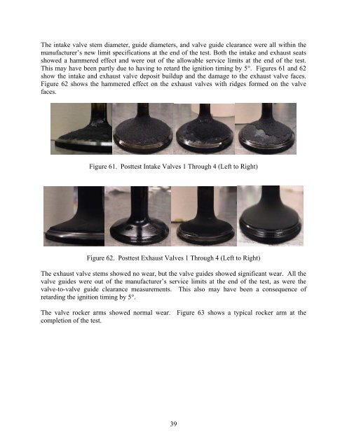
The intake valve stem diameter, guide diameters, and valve guide clearance were all within the<br />
manufacturer’s new limit specifications at the end <strong>of</strong> the test. Both the intake and exhaust seats<br />
showed a hammered effect and were out <strong>of</strong> the allowable service limits at the end <strong>of</strong> the test.<br />
This may have been partly due to having to retard the ignition timing by 5°. Figures 61 and 62<br />
show the intake and exhaust valve deposit buildup and the damage to the exhaust valve faces.<br />
Figure 62 shows the hammered effect on the exhaust valves with ridges formed on the valve<br />
faces.<br />
Figure 61. Posttest Intake Valves 1 Through 4 (Left to Right)<br />
Figure 62. Posttest Exhaust Valves 1 Through 4 (Left to Right)<br />
The exhaust valve stems showed no wear, but the valve guides showed significant wear. All the<br />
valve guides were out <strong>of</strong> the manufacturer’s service limits at the end <strong>of</strong> the test, as were the<br />
valve-to-valve guide clearance measurements. This also may have been a consequence <strong>of</strong><br />
retarding the ignition timing by 5°.<br />
The valve rocker arms showed normal wear. Figure 63 shows a typical rocker arm at the<br />
completion <strong>of</strong> the test.<br />
39