The Retractable Wing RC Aeroplane
The Retractable Wing RC Aeroplane
The Retractable Wing RC Aeroplane

Create successful ePaper yourself
Turn your PDF publications into a flip-book with our unique Google optimized e-Paper software.
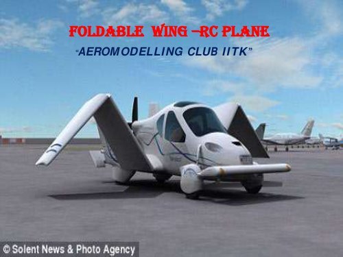
FOLDABLE WING –<strong>RC</strong> PLANE<br />
AEROMODELLING CLUB IITK
PROJECT MEMBERS<br />
ANKITA MITTAL<br />
JEETESH AGRAWAL<br />
KRATIKA AGRAWAL<br />
PRATEEK SAZAWAL<br />
RAVINDRA DHAMA<br />
VIKAS RANA<br />
ankitami@iitk.ac.in<br />
jeetesh@iitk.ac.in<br />
kratika@iitk.ac.in<br />
sazawal@iitk.ac.in<br />
dhama@iitk.ac.in<br />
ranav@iitk.ac.in
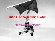
INTRODUCTION<br />
FOLDABLE WING IS A SIMPLE WING WITH<br />
ITS OUTER PARTS FOLDING.IT REQUIRES<br />
SOME SPECIFIC MECHANISM TO FOLD THE<br />
WINGS.IT IS MADE OF BALSA WOOD AND<br />
BALSA PLY AND USED TO GIVE THE PLANE<br />
ITS REQUIRED LIFT.
AIM AND OBJECTIVE<br />
This report is about a remote controlled plane<br />
(<strong>RC</strong> plane) with foldable wings and this action of<br />
folding will also be remote controlled.<br />
<strong>The</strong> basic aim behind folding the wings is that it<br />
can be used both as a car and an airplane.<br />
<strong>The</strong> most important aspect of this kind of plane<br />
is that this can serve as a cheaper version of a<br />
Plane Car.
AIM AND OBJECTIVE<br />
<strong>The</strong> basic plan would be to make first a simple<br />
<strong>RC</strong> plane at first with partitions in each wing<br />
then we make use of hinges and springs to make<br />
the wings fold.
DIFFICULTIES FACED
FINDING A SUITABLE PROBLEM<br />
STATEMENT<br />
First of all the problem must be feasible.<br />
Secondly it must give you the maximum chance<br />
to learn.<br />
Keeping these two points in mind we decided to<br />
go for this model.
HOW TO FOLD THE WING<br />
<strong>The</strong> most challenging aspect of the project is to<br />
find a suitable mechanism to fold the wing.<br />
For this several methods were first tried on the<br />
previous years models available with the club.<br />
Stability of the wing in air was a very critical<br />
issue.
DIFFERENT MECHANISMS TRIED<br />
To fold the wing using a servo alone.<br />
This was not possible since the servo could not<br />
take this much of load.<br />
<strong>The</strong>n we tried it with a hinge.<br />
<strong>The</strong> problem here was that of the fact that the<br />
servo might loose control at any time and one can<br />
not be very sure.
DIFFERENT MECHANISMS TRIED<br />
<strong>The</strong>n keeping these things in mind we decided to<br />
use a rod in combination with the hinge.<br />
In this case we will have to synchronize the<br />
movement of the hinge and the rod.<br />
<strong>The</strong> rod will provide stability and will give proper<br />
strength.<br />
But, it was a very difficult task to synchronize<br />
the movement of the hinge and the rod.
DIFFERENT MECHANISMS TRIED<br />
So, we finally tried to modify the servo in such a<br />
way that with a small movement of the servo we<br />
could achieve a greater change in the angle by<br />
which the wing moves.<br />
For this we used a piece of ply to make the<br />
Even, fiber glass would have worked well for this<br />
purpose, but due to lack of availability we<br />
couldn’t use it.
MAKING WING<br />
Along with that we were working on the wing.<br />
We needed to use a software DESIGNFOIL to<br />
decide upon the airfoil shape and size.<br />
Once this was done we had to make the wing.<br />
Since our project was a folding wing we had to be<br />
extremely careful while assembling and joining<br />
the different airfoils.
MAKING WING<br />
Thick balsa had to be used at the end of every<br />
segment.<br />
A lot of support was provided to the wing using<br />
stringers.<br />
Keeping in mind the complexities of the wing, we<br />
decided to keep it simple and hence we did not<br />
provided any dihedral angle.
AIRFOIL SPECIFICATIONS<br />
Airfoil name NACA-2515-63<br />
Chord length 26 cm<br />
Angle of attack 3 degrees<br />
Lift 0.667<br />
Drag 0.0079<br />
Lift to drag ratio 84.4<br />
Coefficient of lift 0.667
POSITION OF AILERONS<br />
Generally, in a wing on the trailing edge we<br />
provide with flaps and ailerons.<br />
<strong>The</strong> flaps are near to the fuselage and the<br />
ailerons are near the wing tips.<br />
This is done so that the ailerons work effectively.<br />
Since the ailerons work on the principle of<br />
torque.
POSITION OF AILERONS<br />
However in our project since the wing is a folding<br />
one so we can not have either flap or aileron on<br />
the part near the wing tip.<br />
Since ailerons are vital to an aircraft’s movement<br />
we placed only ailerons on the wing.<br />
We kept the aileron a bit bigger in our case<br />
keeping in mind that it is placed near the<br />
fuselage ( generally ailerons are kept far from<br />
fuselage so as to produce large torque )
WING SPECIFICATIONS<br />
<strong>Wing</strong> span = 182 cm<br />
Chord Length = 26 cm<br />
Dihedral angle = 0 degrees<br />
Area of wing = 182*26 cm 2 = 4732 cm 2<br />
Aspect ratio = 7
Length of part 2= Length of part 3 = 45.5 cm<br />
Length of part 1 = Length of part 4 = 45.5 cm
AILERON SPECIFICATIONS<br />
Length of aileron = 40 cm.<br />
Breadth of aileron = 5 cm.<br />
<strong>The</strong> edges of the aileron were<br />
minimize the drag effect.<br />
rounded to
MAKING TAIL<br />
Once different parts of the wing were made, we<br />
moved on to the tail.<br />
One point to be kept in mind while making the<br />
elevator and rudder is that their area too is to be<br />
included in the area of the tail and vertical<br />
stabilizer respectively.
HORIZONTAL TAIL SPECIFICATIONS<br />
<strong>The</strong> maximum length between base and its topmost<br />
portion is 14.5 cm.<br />
<strong>The</strong> minimum distance is 8 cm.<br />
<strong>The</strong> length of the base is 64.5 cm.<br />
<strong>The</strong> tail was inclined at a negative angle of 3 degrees<br />
with respect to the fuselage.
VERTICAL STABILIZER<br />
It was made trapezium shaped with the following<br />
specifications.<br />
Height = 29.3cm<br />
Length of two parallel sides were 2 cm and 23<br />
cm.
RUDDER SPECIFICATIONS<br />
Length = 78 cm<br />
Breadth = 7 cm<br />
Its cross section was airfoil shaped so as to minimize<br />
the drag .
FUSELAGE<br />
We went for an simple fuselage design.<br />
Our project was meant to be a high wing plane<br />
since we do not know flying ( high wing planes<br />
have higher stability,so they are recommended<br />
for beginners)<br />
Generally length of a typical fuselage is 70-90%<br />
of the wing span.<br />
In this case it is 82.5%.<br />
Length of fuselage being 150 cm.
FUSELAGE<br />
After making it we made the base.<br />
We used 3 mm ply to make this basic structure of<br />
the fuselage.<br />
Hence, we need to impart strength to the<br />
fuselage at several places.<br />
Depending on the strength needed at several<br />
places we used single or multi layers of 6 mm<br />
balsa wood or ply.
FUSELAGE<br />
In an aircraft reliability is a very important<br />
issue.<br />
Hence the strength of the plane is a very critical<br />
issue and needed to be handled carefully.
FUSELAGE<br />
To maintain the proper aerodynamic shape of the<br />
fuselage several scanners were set in the hind<br />
section of the fuselage.<br />
Between the scanners trusses were made.<br />
Similarly on the base we made trusses.<br />
At some places 6 mm balsa wood was also used to<br />
give strength.
FUSELAGE<br />
Proper strength must be there because it must<br />
not break due to the vibrations of engine.<br />
Also, the part where Landing Gear have to be<br />
mounted must be very strong, so that it can take<br />
up the vibrations at the time of landing.<br />
<strong>The</strong>se parts were made using double layers of 6<br />
mm ply.
FUSELAGE<br />
For the landing gear a similar piece of ply was<br />
attached at the bottom of the fuselage so as to fix<br />
it in its proper place.<br />
And then we tightened it using nuts and bolts.<br />
We used cycle spokes as wires to connect servos<br />
to different parts of the plane like ailerons,<br />
rudder, elevator.<br />
To the rudder also a landing gear was attached to<br />
ensure the proper landing and take off.
FUEL TANK<br />
We used a mixture of methanol and castor oil.<br />
Level of fuel tank must match the oil input valve.
FINDING THE POSITION OF WING<br />
One of the most important thing is to find a<br />
suitable position for the wing.<br />
For if the centre of gravity of the entire system is<br />
not in between the aerodynamic centre and the<br />
tail then the plane will not be stable.<br />
We did not have exact data required for the<br />
calculations.
FINDING THE POSITION OF WING<br />
What we did then was to try to keep the position<br />
of centre of gravity at a distance of 0.1c to 0.2c<br />
from the aerodynamic centre.<br />
Here c is the chord length.<br />
<strong>The</strong> aerodynamic centre is located at a distance<br />
of 0.25c (approximately) from the leading edge of<br />
the wing for subsonic speeds.
FINDING THE POSITION OF WING<br />
<strong>The</strong> centre of pressure is the position where<br />
actually the total force vector is located.<br />
But in most of the practical cases aerodynamic<br />
centre is used for calculation purposes.
FIXING WING<br />
<strong>The</strong> wing is attached to the fuselage with the<br />
help of thin rubber tubes.<br />
With this we can separate the two parts and<br />
change the position of the wing as per the<br />
requirements.<br />
Like we can use a engine of better capacity.<br />
But with that the weight will increase and so the<br />
position of centre of gravity will vary.<br />
So, we will have to readjust the wings position.
FINALLY FLYING…..<br />
We need to use a five channel transmitter as<br />
against the normal four channel transmitter.<br />
Since in our case we have used an additional<br />
servo for folding the wing.
For more information visit our website<br />
http://students.iitk.ac.in/aeromodelling<br />
Contact<br />
Jeetesh Agrawal<br />
Kratika Agrawal<br />
Tushar Sikroria<br />
jeetesh@iitk.ac.in<br />
kratika@iitk.ac.in<br />
sikroria@iitk.ac.in