Confocal Fiber Displacement Sensor ZW Series - DreamingCode
Confocal Fiber Displacement Sensor ZW Series - DreamingCode
Confocal Fiber Displacement Sensor ZW Series - DreamingCode

Create successful ePaper yourself
Turn your PDF publications into a flip-book with our unique Google optimized e-Paper software.
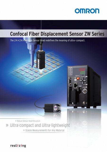
<strong>Confocal</strong> <strong>Fiber</strong> <strong>Displacement</strong> <strong>Sensor</strong> <strong>ZW</strong> <strong>Series</strong><br />
The 24×24×64-mm <strong>Sensor</strong> Head redefines the meaning of ultra-compact.<br />
»<br />
»<br />
Robust <strong>Sensor</strong> Head Structure<br />
Ultra-compact and Ultra-lightweight<br />
»<br />
Stable Measurements for Any Material
2<br />
The <strong>Confocal</strong> <strong>Fiber</strong> <strong>Displacement</strong> <strong>Sensor</strong><br />
beyond triangulation concepts with a new<br />
<strong>Displacement</strong> <strong>Sensor</strong>s are indispensable<br />
in non-contact measurement of heights,<br />
thicknesses, and other dimensions in machine<br />
operation control.However, building<br />
them into the system has always presented<br />
problems.The <strong>Confocal</strong> <strong>Fiber</strong> <strong>Displacement</strong><br />
<strong>Sensor</strong> <strong>ZW</strong> <strong>Series</strong> solves<br />
these problems in ways that were not possible<br />
with traditional triangulation.<br />
The <strong>ZW</strong>-series <strong>Sensor</strong>s provide the compact<br />
size, light weight, immunity to<br />
electrical/magnetic noise, and other features<br />
to make them ideal for solving installation<br />
space problems.<br />
And OMRON’s new confocal principle<br />
provides the measurement resolution that<br />
is needed for operation control.<br />
The <strong>ZW</strong> <strong>Series</strong> solves the problems that<br />
came with laser triangulation, such as deviations<br />
between different materials and<br />
inclination tolerance.<br />
Min.<br />
Resolution<br />
0.25 μm<br />
<strong>ZW</strong> <strong>Series</strong>
3<br />
that goes<br />
principle.<br />
The Three Benefits of OMRON’s White Light <strong>Confocal</strong> Principle<br />
Ultra-compact and<br />
Ultra-lightweight<br />
The slim design measures only 24 × 24 mm.It<br />
weighs only 105 g.This incredibly compact<br />
size could not be achieved with traditional<br />
triangulation.And any objects can be measured<br />
with the <strong>Sensor</strong> mounted perpendicular<br />
to them to save even more space.<br />
P.4<br />
Stable Measurements for<br />
Any Material<br />
Glass<br />
SUS Mirror<br />
Substrate<br />
White ceramic<br />
You can measure objects of any material or<br />
color at the same position.A wide angle characteristic<br />
of ±8° enables high-resolution measurement<br />
of the position even for large objects<br />
with mirror-like surfaces without being affected<br />
by warping.<br />
P.6<br />
Robust <strong>Sensor</strong><br />
Head Structure<br />
No electronic<br />
parts.<br />
The <strong>Sensor</strong> Head is structured to be robust<br />
against electric and magnetic noise for reliable<br />
operation when in locations subject to<br />
noise.Also, the <strong>Sensor</strong> Heads and Flexible<br />
<strong>Fiber</strong> Cables do not give off noise or heat, so<br />
nearby devices are not affected.<br />
P.8
4<br />
Ultra-compact and Ultra-lightweight<br />
Utilize Narrow Spaces in Machines<br />
The 24 × 24-mm <strong>Sensor</strong> Head fits easily into essentially any machine.<br />
Triangulation sensor<br />
Volume<br />
ratio<br />
1/8 8*<br />
64mm<br />
Weight<br />
ratio<br />
1/8 8*<br />
*In-house comparisons.<br />
24mm<br />
24mm<br />
Mounting area Reduced to 1/7*<br />
*In-house comparison.<br />
With traditional triangulation, it was necessary to use either diffuse reflection<br />
or regular reflection depending on the material.However, the confocal<br />
principle used for the <strong>ZW</strong> <strong>Series</strong> eliminates the need to change the<br />
<strong>Sensor</strong> installation even if the material changes.<br />
Traditional Triangulation Model<br />
Diffuse-reflective<br />
<strong>Sensor</strong><br />
Regular-reflective<br />
<strong>Sensor</strong><br />
<strong>ZW</strong> <strong>Series</strong><br />
The <strong>Sensor</strong> can be installed<br />
perpendicular to the object<br />
regardless of the material.<br />
Height Control of a Dispenser Nozzle<br />
Substrate Glass Substrate Glass<br />
<strong>Sensor</strong> Installation in a Row with<br />
No Interference<br />
Mutual interference or space restrictions often prevent<br />
the installation of traditional triangulation sensors<br />
where necessary. Here, the compact <strong>ZW</strong>series<br />
<strong>Sensor</strong> Heads allow you to install more sensors,<br />
in a row or otherwise.<br />
Minimum pitch<br />
24 mm<br />
Non-contact Flatness Inspection of HDD Cases
5<br />
Smooth Movement and Stopping<br />
Using power cylinders to move sensors to measurement positions only<br />
when necessary so that the sensors do not interfere with machine motion<br />
results in delays in measurements while waiting for oscillation to stop<br />
after cylinder operation on if the sensors are heavy.A <strong>ZW</strong>-series <strong>Sensor</strong><br />
Head, however, weighs only<br />
105<br />
g so that<br />
measurements can be made<br />
as soon as the cylinder operation stops.<br />
s.<br />
<strong>ZW</strong> <strong>Series</strong><br />
Time<br />
Degree of<br />
oscillation<br />
Moved.<br />
Stopped.<br />
Degree of<br />
oscillation<br />
Traditional Triangulation Model<br />
Time<br />
Bonding Height Inspection<br />
Flexible <strong>Fiber</strong> Cable for Easy Installation<br />
The Controller connects to the<br />
<strong>Sensor</strong> Head with a 2-mm-diameter<br />
Flexible <strong>Fiber</strong> Cable.The<br />
Cable has cleared a bending<br />
test consisting of 2,000,000*<br />
repetitions for reliable application<br />
on moving parts.<br />
Ultrathin<br />
Cable<br />
Cable diameter: 2 mm<br />
Minimum bending radius: 20 mm<br />
R<br />
*Cable was tested with OMRON’s bending<br />
test consisting of 2,000,000 bends to a 70-mm<br />
bending radius and 1,000,000 bends to a<br />
20-mm bending radius.<br />
Installation in a Cable Carrier<br />
Cable Extendable to 32 m<br />
An Extension <strong>Fiber</strong> Cable can be used between the <strong>Sensor</strong> Head and Controller to extend the distance to up to<br />
32 m.Attach the <strong>Sensor</strong> Head to a moving part and place the Controller in the control panel or other convenient<br />
location to achieve a flexible system design.<br />
Standard <strong>Fiber</strong> Cable<br />
0.3 or 2 m<br />
Extension <strong>Fiber</strong> Cable<br />
30 m max.<br />
<strong>Sensor</strong> Head<br />
Connecting adapter<br />
Controllerr
6<br />
Stable Measurements for Any Material<br />
with Superior Angle Characteristic<br />
Stable Measurements from the Same<br />
Mounting Position Even for Different Materials<br />
There is no need to change or tune the <strong>Sensor</strong> for each<br />
material. Even if the material changes, you can continue to<br />
achieve stable measurements with the same <strong>Sensor</strong> from the<br />
same mounting position.<br />
Regular-reflective workpiece<br />
Diffuse-reflective workpiece<br />
Mirror<br />
Glass<br />
SUS<br />
White ceramic<br />
Substrate<br />
±2 μm or less<br />
±3 μm or less<br />
<strong>ZW</strong> <strong>Series</strong><br />
Stable Measurements<br />
for Any Material to<br />
±2 μm (with the <strong>ZW</strong>-S20)<br />
Linearity<br />
±4 μm or less<br />
±5 μm or less<br />
Traditional Triangulation Model<br />
Large discrepancy between materials.<br />
(Comparisons for <strong>Sensor</strong> with a measuring center distance of 20 mm.)<br />
Linearity for Various Materials<br />
Stable Measurements across Boundaries<br />
between Materials<br />
Mirror<br />
Glass<br />
Measurement Area<br />
Substrate<br />
Measurement Area<br />
(All measurement graphs represent typical examples.)
7<br />
Superior Angle Characteristic<br />
When measuring an object that has a mirror-like<br />
surface with traditional triangulation, performance is<br />
greatly reduced depending on the angel of the <strong>Sensor</strong>.<br />
When many <strong>Sensor</strong>s are used for height control during<br />
glass conveyance, the angles of the <strong>Sensor</strong>s must be<br />
adjusted with high precision during setup.The confocal<br />
<strong>Sensor</strong> <strong>ZW</strong> series enables high-resolution measurements<br />
without strict angle adjustment.This results in<br />
reduction of cost and space for the adjusting jig and<br />
time for adjustment.<br />
* This is not a guaranteed value.<br />
Refer to Characteristic Data (P17)<br />
for typical examples.<br />
Angle<br />
characteristic<br />
±8° *<br />
Height Control during Glass Conveyance<br />
Traditional Triangulation Model<br />
With triangulation, even if the angle is adjusted with high precision during<br />
the setup of the <strong>Sensor</strong>, stable measurement results are difficult to obtain<br />
when the measurement object is warped or inclined.<br />
<strong>ZW</strong> <strong>Series</strong><br />
<strong>ZW</strong>-series <strong>Sensor</strong>s operate on the confocal principle, so highresolution<br />
measurements are possible regardless of inclination and<br />
warping of the measurement object.<br />
Error (μm)<br />
30<br />
20<br />
10<br />
0<br />
-10<br />
-20<br />
-30<br />
-1 -0.5 0 0.5 1<br />
Distance (mm)<br />
+4°<br />
Measurement is<br />
not possible.<br />
+2°<br />
+1.5°<br />
0°<br />
-1.5°<br />
-2°<br />
-4°<br />
Measurement is<br />
not possible.<br />
Error (μm)<br />
30<br />
+4°<br />
20<br />
10<br />
0<br />
+2°<br />
+1.5°<br />
0°<br />
-1.5°<br />
-10<br />
-20<br />
-2°<br />
-4°<br />
-30<br />
-1 -0.5 0 0.5 1<br />
Distance (mm) (<strong>Sensor</strong>: <strong>ZW</strong>-S20)<br />
No Discrepancy in the Measurement Point<br />
Superior angle characteristics are not the only advantage of a<br />
confocal principle.With a traditional triangulation, the measurement<br />
position and spot size vary with the height. This<br />
means there are times when the position cannot be measured<br />
with high resolution due to warping and inclination.With the<br />
confocal principle used for the <strong>ZW</strong> <strong>Series</strong>, the measurement<br />
point remains the same at any position in the measuring<br />
range so that precise measurements can always be made.<br />
Traditional Triangulation Model<br />
Measurement position Varies<br />
with the Height<br />
<strong>ZW</strong> <strong>Series</strong><br />
No Discrepancy in the<br />
Measurement Position
8<br />
Robust <strong>Sensor</strong> Head Structure<br />
No Noise<br />
Reduced Work for<br />
EMC Countermeasures<br />
Not Affected by Noise<br />
To ensure high-resolution measurements with normal sensors, countermeasures<br />
must be implemented to protect the sensor from the electromagnetic<br />
noise that is emitted by any nearby devices.The <strong>ZW</strong>-series<br />
<strong>Sensor</strong> Heads, however, contain no electronic parts to enable stable<br />
measurements even near power sections.Also, the <strong>Fiber</strong> Cable<br />
that connects the <strong>Sensor</strong> Head to the Controller can be placed near<br />
power lines or other cables that emit noise without affecting operation.<br />
Traditional Triangulation Model<br />
Changes in Measurement<br />
Values Caused by Noise<br />
<strong>ZW</strong> <strong>Series</strong><br />
Measurements are not affected by<br />
noise and remain stable.<br />
Measurement<br />
value<br />
Measurement<br />
value<br />
Noise<br />
waveform<br />
Noise<br />
waveform<br />
Time<br />
Time<br />
No Noise Emission<br />
No electronic parts are used in the <strong>ZW</strong>-series <strong>Sensor</strong> Heads or<br />
<strong>Fiber</strong> Cables, so they give off no electromagnetic noise. You can<br />
therefore use them reliably together with other devices.<br />
Traditional Triangulation Model<br />
Electronic parts<br />
<strong>ZW</strong> <strong>Series</strong><br />
<strong>Fiber</strong> Cable<br />
Substrate Height Inspection<br />
No electronic parts.<br />
Electromagnetic tic noise<br />
is<br />
emitted from<br />
No Noise Emitted.<br />
the sensor and from cables.
9<br />
No Heat Generation<br />
Reduced Work in Thermal Design<br />
In high-resolution machine control, the heat generated by a sensor head<br />
can adversely affect nearby equipment and cause the error to<br />
increase.The <strong>ZW</strong>-series <strong>Sensor</strong> Heads, however, generate no heat and<br />
therefore do not affect nearby equipment.You can also install many <strong>Sensor</strong><br />
Heads side by side and still be sure of reliable operation.<br />
Traditional Triangulation Model<br />
<strong>ZW</strong> <strong>Series</strong><br />
+2℃<br />
+0℃<br />
No electronic<br />
parts in the<br />
<strong>Sensor</strong> Head.<br />
Change in Temperature after 1.5 Hours of Operation<br />
An LED is used in<br />
place of a laser for<br />
the light source to<br />
eliminate the need<br />
for safety measures.<br />
No Electronic Parts<br />
Reduced Maintenance Costs<br />
<strong>Displacement</strong> sensors are often installed in moving sections and other locations<br />
that are subject to vibration. It is important that they can withstand<br />
this type of environment.The <strong>ZW</strong>-series <strong>Sensor</strong> Heads consist of only the<br />
lenses and fiber. They contain no electronic parts or PCBs.The number of<br />
parts in them is greatly less than for a traditional sensor that uses triangulation,<br />
and this greatly reduces the maintenance frequency.Also they use<br />
LEDs as the source of light, so the safety measures that are required for<br />
lasers are not necessary either.<br />
Traditional Triangulation Model<br />
Laser diode<br />
<strong>ZW</strong> <strong>Series</strong><br />
Electric circuits<br />
and the light<br />
source are<br />
contained in the<br />
Controller.<br />
Electronic parts<br />
Special set of<br />
lenses that<br />
require no drive<br />
system.<br />
No electronic<br />
parts.
10<br />
White Light <strong>Confocal</strong> Principle<br />
To achieve a compact <strong>Sensor</strong> Head and high-resolution measurements,<br />
the <strong>ZW</strong> <strong>Series</strong> uses a white light confocal principle to detect objects.<br />
This principle is described below.<br />
<strong>Confocal</strong> principle<br />
<strong>Confocal</strong> Light Emission and Reception<br />
Based on the confocal principle, the emitted light and received light are positioned along the<br />
same axis. Light is received only when it is focused on the measurement object, allowing the<br />
height to be calculated.Unlike triangulation, the received light waveform is not disrupted by<br />
the material or inclination of the measurement object. The received light waveform is always<br />
stable, which enables high-resolution measurements.<br />
Object Located at Focal Point<br />
The reflected light is focused at the same<br />
point as the emitted light.The reflected<br />
light becomes the received light signal.<br />
Object Not Located<br />
at Focal Point<br />
Reflected light is not received<br />
because the reflected light is<br />
not focused at the light emission<br />
point.<br />
Inclination and<br />
Differences in Materials<br />
Even if the measurement object<br />
is inclined or contains different<br />
materials, the reflected light will<br />
be focused at the light emission<br />
point as long as the measurement<br />
object is at the focal point.<br />
Light emission point<br />
=<br />
Light<br />
emission<br />
point<br />
Light<br />
emission<br />
point<br />
Focal point<br />
=<br />
Focal point<br />
<strong>Confocal</strong> point<br />
White light<br />
Focal<br />
point<br />
Emitted light<br />
Reflected light<br />
Focal point<br />
OCFL Module<br />
The OCFL module contains a special<br />
lens set developed by OMRON that<br />
changes the focal point for each color<br />
(i.e., wavelength) of white light.The spot<br />
diameter is the same at any position<br />
within the measuring range. It does not<br />
change the way it does for a triangulation.<br />
High-precision lens manufacturing<br />
technology has allowed us to achieve a<br />
lens structure that is extremely small<br />
and that also does not require a drive<br />
mechanism.<br />
*OCFL : Omron Chromatic Focus Lens<br />
The height is calculated from the<br />
position at which the reflected light<br />
was received.<br />
White<br />
White Light Separation into Colors<br />
with Different Wavelengths at Emission<br />
The white light from the LED is focused at different points for each color (i.e., wavelength) due to a special<br />
set of lenses in the OCFL module in the <strong>Sensor</strong> Head.As a result, only the color of light that is focused on<br />
the measurement object is returned, allowing the distance from the <strong>Sensor</strong> Head to the measurement<br />
object to be calculated based on the color of the reflected light.The <strong>Sensor</strong> Head contains the special set<br />
of lenses that separates white light into different colors and the Controller contains the white LED light<br />
source, and the spectroscope and processor that convert the color of the reflected light to a distance.There<br />
is no needs for a lens drive mechanism or electronic parts in the <strong>Sensor</strong> Head, even though they were<br />
considered to be standard in previous confocal models. This achieves a much more compact design and<br />
much greater immunity to noise than triangulation models and or previous confocal models.<br />
The height is detected based on<br />
the wavelength.<br />
White LED<br />
light source<br />
High<br />
Pass<br />
Low 100.300<br />
PARALLEL<br />
USB<br />
RS232C<br />
100.250<br />
ROM<br />
HEAD<br />
ZERO<br />
ENABLE<br />
<strong>Fiber</strong> Cable<br />
spectroscope<br />
Receiver<br />
Processor<br />
Light is not<br />
received.<br />
White light<br />
OCFL Module<br />
Distance<br />
NEAR<br />
Colors are separated<br />
along the height direction.<br />
Patent Pending<br />
The reflected light of the wavelength that was<br />
focused on the surface of the measurement<br />
object passes through the fiber and the spectroscope<br />
in the Controller converts the wavelength<br />
to a distance.<br />
FAR<br />
Amount of<br />
received light
11<br />
Problems with Previous Models<br />
Triangulation<br />
Laser diode<br />
Reciever<br />
FAR<br />
NEAR<br />
Triangulation measures the height of an object based on the position<br />
of the spot on a receiver (CCD or CMOS).The peak, center<br />
of gravity, and other features are calculated from the received<br />
light waveform to reduce error, but in principle, the received<br />
waveform is offset or disrupted due to differences in materials or<br />
inclination. This results in measurement error.<br />
Light Reception for Different Materials<br />
Emission lens<br />
Reception lens<br />
Waveform<br />
disrupted<br />
NEAR<br />
Receiver<br />
Ideal<br />
waveform<br />
FAR<br />
Different materials have different reflection<br />
factors. This disrupts the<br />
waveform that is received on the<br />
receiver.The peak in the waveform<br />
or the center of gravity are used to<br />
calculate the height, but error will<br />
remain in the measurement results.<br />
Light Reception for Inclination<br />
Normal <strong>Confocal</strong> Principle<br />
Waveform<br />
disrupted<br />
NEAR<br />
Receiver<br />
Ideal<br />
waveform<br />
FAR<br />
If the measurement object is inclined,<br />
the received waveform is<br />
offset or disrupted due to the effects<br />
of aberration. This results in measurement<br />
error.<br />
Processor<br />
Laser diode<br />
Pinhole<br />
Receiver<br />
In a normal confocal model, a stage and lens are driven vertically<br />
to change the focal point.This requires a more complex structure,<br />
and the large number of parts interferes with<br />
downsizing.The use of a laser beam increases the chances of interference,<br />
and the received light waveform can be disrupted by<br />
the surface conditions within the small spot on the measurement<br />
object.<br />
Drive processor<br />
Lens<br />
+<br />
Lens drive<br />
circuit<br />
Move the stage<br />
and lens vertically.<br />
Stage
12<br />
Smart Application of<br />
High-resolution Measurements<br />
System Configuration<br />
Basic Configuration<br />
RS-232C, parallel,<br />
analog, or Ethernet<br />
PLC<br />
<strong>ZW</strong>-S<strong>Sensor</strong> Head<br />
Computer<br />
Calibration ROM<br />
(included with <strong>Sensor</strong> Head)<br />
<strong>ZW</strong>-C1<br />
Controller<br />
Ethernet<br />
<strong>ZW</strong>-SW101<br />
Smart Monitor <strong>ZW</strong><br />
(Setting Software)<br />
A computer (to use the Smart Monitor <strong>ZW</strong>) and a PLC cannot be connected via Ethernet at the same time.<br />
Smart Monitor <strong>ZW</strong> Setting Software (Computer Software)<br />
This Setting Software allows you to use a computer to make the ideal setup and to collect and analyze data with powerful functions.<br />
Display the Received Light Waveforms<br />
You can display the waveforms that were received on the image<br />
element.This feature is very effective when measuring transparent<br />
objects, which return multiple waveforms.<br />
Data Logging<br />
You can log measurement results at various times to evaluate and<br />
record inspection results.<br />
Received waveform<br />
*Some of the data may not be logged depending on the computer<br />
environment.Use a computer with the recommended system<br />
requirements or better.<br />
You can connect the computer and Controller via Ethernet so that you can set up and install the system while monitoring the waveform<br />
from a computer that is close to the <strong>Sensor</strong> Head even if the Controller is installed in a control panel at a more remote location.<br />
Worksite<br />
Up to 32 m<br />
Extension <strong>Fiber</strong> Cable<br />
Control panel<br />
Connecting adapter<br />
(<strong>ZW</strong>-XFC)<br />
(<strong>ZW</strong>-XFR)<br />
Ethernet cable
13<br />
Order Information<br />
● <strong>Sensor</strong> Head<br />
20±1 mm<br />
30±3.5 mm<br />
40±6 mm<br />
40<br />
30<br />
20<br />
0<br />
Measuring range<br />
Spot diameter<br />
Static resolution<br />
Model<br />
Note: When ordering, specify the cable length (0.3 m, 2.0 m).<br />
The specifications of the "upcoming" product are subject to change without notice.<br />
●Controller<br />
20±1 mm<br />
40 µm dia.<br />
0.25 µm<br />
30±3.5 mm<br />
60 µm dia.<br />
0.25 µm<br />
Appearance Power supply Output type Model<br />
40±6 mm<br />
80 µm dia.<br />
0.25 µm<br />
<strong>ZW</strong>-S20 <strong>ZW</strong>-S30 (Upcoming) <strong>ZW</strong>-S40<br />
NPN<br />
24 VDC<br />
PNP<br />
Note: Setting software Smart Monitor <strong>ZW</strong> is attached.<br />
<strong>ZW</strong>-C10T<br />
<strong>ZW</strong>-C10AT (See note.)<br />
<strong>ZW</strong>-C15T<br />
<strong>ZW</strong>-C15AT (See note.)<br />
●Cable<br />
Appearance Item Cable length Model<br />
<strong>Sensor</strong> Head - Controller<br />
Extension <strong>Fiber</strong> Cable<br />
(flexible cable)<br />
(<strong>Fiber</strong> Adapter <strong>ZW</strong>-XFC<br />
provided)<br />
<strong>Fiber</strong> Adapter<br />
(between <strong>Sensor</strong> Head pre-wired<br />
cable and Extension <strong>Fiber</strong> Cable)<br />
2 m <strong>ZW</strong>-XF02R<br />
5 m <strong>ZW</strong>-XF05R<br />
10 m <strong>ZW</strong>-XF10R<br />
20 m <strong>ZW</strong>-XF20R<br />
30 m <strong>ZW</strong>-XF30R<br />
-- <strong>ZW</strong>-XFC<br />
Parallel cable 2 m <strong>ZW</strong>-XCP2<br />
RS-232C Cable<br />
For personal computer<br />
2 m <strong>ZW</strong>-XRS2<br />
RS-232C Cable<br />
For PLC/programmable terminal<br />
2 m <strong>ZW</strong>-XPT2<br />
●Setting Software<br />
Item<br />
Smart Monitor <strong>ZW</strong><br />
Model<br />
<strong>ZW</strong>-SW101
14<br />
Specifications<br />
●<strong>Sensor</strong> Head<br />
Item <strong>ZW</strong>-S20 <strong>ZW</strong>-S40<br />
Measuring center distance 20 mm 40 mm<br />
Measuring range ±1 mm ±6 mm<br />
Static resolution (See note 1.) 0.25 μm 0.25 μm<br />
Linearity (See note 2.) ±1.2 μm ±7.0 μm<br />
Near 45 μm dia. 90 μm dia.<br />
Spot diameter<br />
(See note 3.)<br />
Center 40 μm dia. 80 μm dia<br />
Far 45 μm dia. 90 μm dia<br />
Measuring cycle<br />
500 μs to 10 ms<br />
Operating ambient illumination<br />
Ambient temperature range<br />
Ambient humidity range<br />
Degree of protection<br />
Note: 1. Capacity value when Omron standard mirror surface target is measured at the measurement center distance as the average of 4,096<br />
times.<br />
2. Material setting for the Omron standard mirror surface target: Error from an ideal straight line when measuring on mirror surface.<br />
The reference values for linearity when targets to measure other than the above are as in the table below.<br />
3. Capacity value defined by 1/e 2 (13.5%) of the center optical intensity in the measured area.<br />
4. Temperature characteristic at the measurement center distance when fastened with an aluminum jig between the <strong>Sensor</strong> Head and the<br />
target and the <strong>Sensor</strong> Head and the controller are set in the same temperature environment.<br />
●Setting Software Smart Monitor <strong>ZW</strong> <strong>ZW</strong>-SW101<br />
Recommended System Requirements<br />
Illumination on object surface 10,000 lx or less: incandescent light<br />
Operating: 0 to 50°C, Storage: −15 to 60°C<br />
(with no icing or condensation)<br />
Operating and storage: 35% to 85%<br />
(with no condensation)<br />
IP40 (IEC60529)<br />
Vibration resistance (destructive) 10 to 150 Hz, 0.35 mm single amplitude, 80 min each in X, Y, and Z directions<br />
Shock resistance (destructive)<br />
150 m/s 2 3 times each in six directions (up/down, left/right, forward/backward)<br />
Temperature characteristic (See note 4.) 1.5 μm/°C 4.8 μm/°C<br />
Case:<br />
aluminum die-cast<br />
Materials<br />
<strong>Fiber</strong> cable sheat: PVC<br />
Calibration ROM: PC<br />
<strong>Fiber</strong> cable length<br />
0.3 m, 2 m (Flex-resistant cable)<br />
<strong>Fiber</strong> cable minimum bending radius 20 mm<br />
Insulation resistance (Calibration ROM) Between case and all terminals: 20 MΩ (by 250 V megger)<br />
Dielectric strength (Calibration ROM) Between case and all terminals: 1,000 VAC, 50/60 Hz, 1 min<br />
Weight<br />
Approx. 105 g (Chassis, fiber cable total)<br />
Accessories<br />
Item<br />
OS<br />
Item <strong>ZW</strong>-S20 <strong>ZW</strong>-S40<br />
Grass ±1.2 μm ±7.0 μm<br />
SUS BA ±1.4 μm ±8.5 μm<br />
White ceramic ±1.7 μm ±9.5 μm<br />
CPU<br />
Memory<br />
Free hard disk space<br />
Display<br />
Supported languages<br />
Communication port<br />
Instruction sheet, Fixing screw (M2) for Calibration ROM, Precautions for correct use<br />
Condition<br />
Windows 7 (32 or 64-bit version)<br />
Windows XP (Service Pack3 or more, 32-bit version)<br />
Intel Pentium III, 850 MHz or more (2 GHz or more is recommended.)<br />
1 GB or more<br />
50 MB or more<br />
1024 x 768 dots or more, 16 million colors or more<br />
Japanese/English<br />
Ethernet port<br />
• Windows, Windows XP, and Windows 7 are registered trademarks of Microsoft Corporation in the USA and other countries.<br />
• Other company names and product names in this document are the trademarks or registered trademarks of their respective companies.
15<br />
●Controller<br />
Item <strong>ZW</strong>-C10T <strong>ZW</strong>-C10AT <strong>ZW</strong>-C15T <strong>ZW</strong>-C15AT<br />
Input/Output type NPN PNP<br />
Number of connected <strong>Sensor</strong> Heads<br />
1 per Controller<br />
<strong>Sensor</strong> Head compatibility<br />
Available<br />
Light source for measurement<br />
White LED<br />
Segment Main display<br />
11-segment red display, 6 digits<br />
display Sub-display<br />
11-segment green display, 6 digits<br />
LED display Status indicators<br />
HIGH (orange), PASS (green), LOW (orange), STABILITY (green), ZERO (green),<br />
ENABLE (green), THRESHOLD-H (orange), THRESHOLD-L (orange), RUN (green)<br />
Ethernet<br />
1 port , 100BASE-TX, 10BASE-T<br />
RS-232C<br />
1 port, 115,200 bps max.<br />
Judgment output (HIGH1/PASS1/LOW1) Transistor output system<br />
BUSY output (BUSY1)<br />
Output voltage:<br />
21.6 to 30 VDC<br />
Load current:<br />
50 mA or less<br />
ALARM output (ALARM1) Residual voltage when turning ON: 1.2 V or less<br />
ENABLE output (ENABLE) Leakage voltage when turning OFF: 0.1 mA or less<br />
20-pole Analog voltage output (OUT1V) −10 to 10 V, Output impedance: 100 Ω<br />
terminal<br />
block Analog current output (OUT1A) 4 to 20 mA, Max. load resistance: 300 Ω<br />
LED OFF input (LED OFF1) DC input system<br />
ZERO RESET input (BUSY1) Input voltage:<br />
24 VDC ±10% (21.6 to 26.4 VDC)<br />
Input current:<br />
7 mA Typ. (24 VDC)<br />
TIMING output (TIMING1)<br />
Voltage/Current when turning ON: 19 V/3 mA or more<br />
RESET output (RESET1)<br />
Voltage/Current when turning OFF:5 V/1 mA or less<br />
Measured value output<br />
(BAINARY 0 to 20) Transistor output system<br />
Output voltage:<br />
21.6 to 30 VDC<br />
External<br />
Gate signal output<br />
Load current:<br />
50 mA or less<br />
interface<br />
(GATE)<br />
Residual voltage when turning ON: 1.2 V or less<br />
Binary<br />
Selected task output<br />
(BINARY_ OUT1/2)<br />
Leakage voltage when turning OFF: 0.1 mA or less<br />
DC input system<br />
Input voltage:<br />
24 VDC ±10% (21.6 to 26.4 VDC)<br />
Selected task input<br />
Input current:<br />
7 mA Typ. (24 VDC)<br />
52-pole<br />
(BAINARY_ SEL1/2)<br />
Voltage/Current when turning ON: 19 V/3 mA or more<br />
extension<br />
Voltage/Current when turning OFF: 5 V/1 mA or less<br />
connector<br />
Transistor output system<br />
Output voltage:<br />
21.6 to 30 VDC<br />
Selected bank output<br />
Load current:<br />
50 mA or less<br />
(BANK_OUT 1 to 3)<br />
Residual voltage when turning ON: 1.2 V or less<br />
Bank<br />
Leakage voltage when turning OFF: 0.1 mA or less<br />
DC input system<br />
Input voltage:<br />
24 VDC ±10% (21.6 to 26.4 VDC)<br />
Selected bank input<br />
Input current:<br />
7 mA Typ. (24 VDC)<br />
(BANK_SEL 1 to 3)<br />
Voltage/Current when turning ON: 19 V/3 mA or more<br />
Voltage/Current when turning OFF:5 V/1 mA or less<br />
Exposure time<br />
Auto/Manual<br />
Measuring cycle<br />
500 μm to 10 ms<br />
Material setting<br />
Standard/Mirror/Diffusion surfaces<br />
Measurement Item<br />
Height/Thickness/Calculation<br />
Main functions<br />
Filtering<br />
Median/Average/Differentiation/High pass/Low pass/Band pass<br />
Outputs<br />
Scaling/Different holds/Zero reset/Logging for a measured value<br />
Display<br />
Measured value/Threshold value/Analog output voltage or current value/<br />
Judgment result/Resolution/Exposure time<br />
Number of configurable banks<br />
Max. 8 banks<br />
Task process<br />
Multi-task (up to 4 tasks per bank)<br />
System<br />
Save/Initialization/Display measurement information/Communication settings/<br />
<strong>Sensor</strong> Head calibration/Key-lock/Trigger-key input<br />
Power supply voltage<br />
21.6 to 26.4 VDC (including ripple)<br />
Ratings<br />
Current consumption<br />
500 mA max.<br />
Insulation resistance<br />
Across all lead wires and controller case: 20 MΩ (by 250 V megger)<br />
Dialectic strength<br />
Across all lead wires and controller case: 1,000 VAC, 50/60 Hz, 1 min.<br />
Degree of protection<br />
IP20 (IEC60529)<br />
Vibration resistance (destructive)<br />
10 to 55 Hz, 0.35-mm single amplitude, 50 min each in X, Y, and Z directions<br />
Environmental<br />
immunity<br />
Grounding<br />
Materials<br />
Weight<br />
Accessories<br />
Shock resistance (destructive)<br />
Ambient temperature<br />
Ambient humidity<br />
150 m/s 2 , 3 times each in six directions (up/down, left/right, forward/backward)<br />
Operating: 0 to 40°C<br />
Storage: −15 to 60°C (with no icing or condensation)<br />
Operating and storage: 35% to 85% (with no condensation)<br />
D-type grounding (Grounding resistance of 100 Ω or less)<br />
Note: For conventional Class D grounding<br />
Case: PC<br />
Approx. 750 g (main unit only)<br />
Instruction sheet,<br />
Member registration<br />
sheet<br />
Instruction sheet,<br />
Member registration<br />
sheet and software for<br />
setting (CD-ROM)<br />
Instruction sheet,<br />
Member registration<br />
sheet<br />
Instruction sheet,<br />
Member registration<br />
sheet and software for<br />
setting (CD-ROM)
16<br />
Characteristic data (typical examples)<br />
●Linearity Characteristic by Materials<br />
+<br />
Measuring center distance 0<br />
<strong>ZW</strong>-S20<br />
−<br />
Material setting: Normal Material setting: Mirror surface Material setting: Diffusion surface<br />
Error [μm]<br />
10<br />
8<br />
6<br />
4<br />
2<br />
0<br />
−2<br />
−4<br />
−6<br />
Mirror<br />
SUS BA<br />
Glass<br />
−8<br />
White ceramic<br />
−10<br />
−1 −0.8 −0.6 −0.4 −0.2 0 0.2 0.4 0.6 0.8 1<br />
Distance [mm]<br />
Error [μm]<br />
10<br />
8<br />
6<br />
4<br />
2<br />
0<br />
−2<br />
−4<br />
Mirror<br />
−6<br />
SUS BA<br />
Glass<br />
−8<br />
−10<br />
−1 −0.8 −0.6 −0.4 −0.2 0 0.2 0.4 0.6 0.8 1<br />
Distance [mm]<br />
Error [μm]<br />
10<br />
8<br />
6<br />
4<br />
2<br />
0<br />
−2<br />
−4<br />
White ceramic<br />
−6<br />
−8<br />
−10<br />
−1 −0.8 −0.6 −0.4 −0.2 0 0.2 0.4 0.6 0.8 1<br />
Distance [mm]<br />
<strong>ZW</strong>-S40<br />
Material setting: Normal Material setting: Mirror surface Material setting: Diffusion surface<br />
Error [μm]<br />
30<br />
25<br />
20<br />
15<br />
10<br />
5<br />
0<br />
−5<br />
−10<br />
Mirror<br />
−15<br />
SUS BA<br />
−20<br />
Glass<br />
−25<br />
White ceramic<br />
−30<br />
−6 −5 −4 −3 −2 −1 0 1 2 3 4 5 6<br />
Distance [mm]<br />
Error [μm]<br />
30<br />
25<br />
20<br />
15<br />
10<br />
5<br />
0<br />
−5<br />
−10<br />
−15<br />
−20<br />
−25<br />
Mirror<br />
SUS BA<br />
Glass<br />
−30<br />
−6 −5 −4 −3 −2 −1 0 1 2 3 4 5 6<br />
Distance [mm]<br />
Error [μm]<br />
30<br />
25<br />
20<br />
15<br />
10<br />
5<br />
0<br />
−5<br />
−10<br />
−15<br />
White ceramic<br />
−20<br />
−25<br />
−30<br />
−6 −5 −4 −3 −2 −1 0 1 2 3 4 5 6<br />
Distance [mm]
17<br />
●Angle Characteristic *<br />
α direction<br />
β direction<br />
Model nameplate<br />
Slope angle +<br />
Slope angle +<br />
<strong>ZW</strong>-S20<br />
Mirror α direction<br />
Error [μm]<br />
Distance [mm]<br />
White ceramic α direction<br />
Error [μm]<br />
<strong>ZW</strong>-S40<br />
Mirror α direction<br />
Error [μm]<br />
Slope angle −<br />
10<br />
8<br />
6<br />
4<br />
2<br />
0<br />
−2<br />
−4<br />
−6<br />
−8<br />
Slope angle<br />
8°<br />
0°<br />
−8°<br />
−10<br />
−1 −0.5 0 0.5 1<br />
10<br />
8<br />
6<br />
4<br />
2<br />
0<br />
−2<br />
−4<br />
Slope angle<br />
−6<br />
50°<br />
0°<br />
−8<br />
−50°<br />
−10<br />
−1 −0.5 0 0.5 1<br />
Distance [mm]<br />
30<br />
20<br />
10<br />
0<br />
−10<br />
Slope angle<br />
5°<br />
−20<br />
0°<br />
−5°<br />
−30<br />
−6 −4 −2 0 2 4 6<br />
Distance [mm]<br />
White ceramic α direction<br />
30<br />
20<br />
Slope angle −<br />
Mirror β direction<br />
Error [μm]<br />
10<br />
8<br />
6<br />
4<br />
2<br />
0<br />
−2<br />
−4<br />
−6<br />
−8<br />
Slope angle<br />
8°<br />
0°<br />
−8°<br />
−10<br />
−1 −0.5 0 0.5 1<br />
Distance [mm]<br />
White ceramic β direction<br />
Error [μm]<br />
10<br />
8<br />
6<br />
4<br />
2<br />
0<br />
−2<br />
−4<br />
Slope angle<br />
−6<br />
50°<br />
0°<br />
−8<br />
−50°<br />
−10<br />
−1 −0.5 0 0.5 1<br />
Distance [mm]<br />
Mirror β direction<br />
Error [μm]<br />
30<br />
20<br />
10<br />
0<br />
−10<br />
Slope angle<br />
5°<br />
−20<br />
0°<br />
−5°<br />
−30<br />
−6 −4 −2 0 2 4 6<br />
Distance [mm]<br />
White ceramic β direction<br />
30<br />
20<br />
Error [μm]<br />
10<br />
0<br />
−10<br />
Slope angle<br />
50°<br />
−20<br />
0°<br />
−50°<br />
−30<br />
−6 −4 −2 0 2 4 6<br />
10<br />
0<br />
−10<br />
Slope angle<br />
50°<br />
−20<br />
0°<br />
−50°<br />
−30<br />
−6 −4 −2 0 2 4 6<br />
Distance [mm]<br />
Distance [mm]<br />
* The above show the results after executing scaling.<br />
Error [μm]
18<br />
External Dimensions<br />
<strong>Sensor</strong> Head<br />
<strong>ZW</strong>-S20/-S40<br />
Standard surface<br />
Four, M3<br />
4±0.1<br />
Standard<br />
surface<br />
Four, 3.5 dia.<br />
(Mounting holes)<br />
4<br />
(Unit: mm)<br />
16±0.1<br />
43±0.1<br />
16±0.1<br />
Mounting hole dimensions<br />
Standard<br />
surface<br />
43 16<br />
16<br />
Measurement<br />
center<br />
M (See note)<br />
M (See note)<br />
Standard fiber cable (2.0 dia.)<br />
Connector<br />
Note:<br />
Model L M X<br />
<strong>ZW</strong>-S20 20 1 11.8<br />
<strong>ZW</strong>-S40 40 6 11.7<br />
X(See note)<br />
24<br />
24<br />
12<br />
Measurement end<br />
FAR<br />
Measurement<br />
CENTER<br />
Measurement end<br />
NEAR<br />
L (See note)<br />
Lighting and<br />
receiving axis<br />
64 (40)<br />
Caution<br />
label<br />
(50)<br />
(42)<br />
(10 dia.)<br />
Controller<br />
<strong>ZW</strong>-C10T/-C15T<br />
128<br />
124<br />
34.9<br />
40.8<br />
6<br />
72<br />
(14.9)<br />
127.5<br />
DIN track attachment hook<br />
40<br />
Four, 4.5 dia.<br />
70<br />
70±0.1<br />
14.5<br />
Extension <strong>Fiber</strong> Cable<br />
<strong>ZW</strong>-XF02R/-XF05R/-XF10R/-XF20R/-XF30R<br />
FC connector<br />
43<br />
(42)<br />
<strong>Fiber</strong> Cable (2.0 dia.)<br />
Installation holes<br />
Four, M4 depth 6.0 MAX.<br />
L (See note)<br />
43±0.1<br />
Mounting hole dimensions<br />
FC connector<br />
(10 dia.)<br />
(42)<br />
(50)<br />
Note: The following table lists cable<br />
lengths per models.<br />
Model Cable length L<br />
<strong>ZW</strong>-XF02R 2 m 2,000±20<br />
<strong>ZW</strong>-XF05R 5 m 5,000±50<br />
<strong>ZW</strong>-XF10R 10 m 10,000±100<br />
`<strong>ZW</strong>-XF20R 20 m 20,000±200<br />
<strong>ZW</strong>-XF30R 30 m 30,000±300
READ AND UNDERSTAND THIS CATALOG<br />
Please read and understand this catalog before purchasing the products. Please consult your OMRON representative if you have any questions or comments.<br />
WARRANTY<br />
OMRON’s exclusive warranty is that the products are free from defects in materials and workmanship for a period of one year (or other period if<br />
specified) from date of sale by OMRON.<br />
OMRON MAKES NO WARRANTY OR REPRESENTATION, EXPRESS OR IMPLIED, REGARDING NON-INFRINGEMENT, MERCHANTABILITY, OR<br />
FITNESS FOR PARTICULAR PURPOSE OF THE PRODUCTS. ANY BUYER OR USER ACKNOWLEDGES THAT THE BUYER OR USER ALONE HAS<br />
DETERMINED THAT THE PRODUCTS WILL SUITABLY MEET THE REQUIREMENTS OF THEIR INTENDED USE. OMRON DISCLAIMS ALL OTHER<br />
WARRANTIES, EXPRESS OR IMPLIED.<br />
LIMITATIONS OF LIABILITY<br />
OMRON SHALL NOT BE RESPONSIBLE FOR SPECIAL, INDIRECT, OR CONSEQUENTIAL DAMAGES, LOSS OF PROFITS OR COMMERCIAL LOSS IN<br />
ANY WAY CONNECTED WITH THE PRODUCTS, WHETHER SUCH CLAIM IS BASED ON CONTRACT, WARRANTY, NEGLIGENCE, OR STRICT LIABILITY.<br />
In no event shall responsibility of OMRON for any act exceed the individual price of the product on which liability is asserted.<br />
IN NO EVENT SHALL OMRON BE RESPONSIBLE FOR WARRANTY, REPAIR, OR OTHER CLAIMS REGARDING THE PRODUCTS UNLESS<br />
OMRON’S ANALYSIS CONFIRMS THAT THE PRODUCTS WERE PROPERLY HANDLED, STORED, INSTALLED, AND MAINTAINED AND<br />
NOT SUBJECT TO CONTAMINATION, ABUSE, MISUSE, OR INAPPROPRIATE MODIFICATION OR REPAIR.<br />
SUITABILITY FOR USE<br />
THE PRODUCTS CONTAINED IN THIS CATALOG ARE NOT SAFETY RATED. THEY ARE NOT DESIGNED OR RATED FOR ENSURING<br />
SAFETY OF PERSONS, AND SHOULD NOT BE RELIED UPON AS A SAFETY COMPONENT OR PROTECTIVE DEVICE FOR SUCH<br />
PURPOSES. Please refer to separate catalogs for OMRON's safety rated products.<br />
OMRON shall not be responsible for conformity with any standards, codes, or regulations that apply to the combination of products in the<br />
customer’s application or use of the product.<br />
At the customer’s request, OMRON will provide applicable third party certification documents identifying ratings and limitations of use that apply<br />
to the products. This information by itself is not sufficient for a complete determination of the suitability of the products in combination with the end<br />
product, machine, system, or other application or use.<br />
The following are some examples of applications for which particular attention must be given. This is not intended to be an exhaustive list of all<br />
possible uses of the products, nor is it intended to imply that the uses listed may be suitable for the products:<br />
• Outdoor use, uses involving potential chemical contamination or electrical interference, or conditions or uses not described in this document.<br />
• Nuclear energy control systems, combustion systems, railroad systems, aviation systems, medical equipment, amusement machines, vehicles,<br />
safety equipment, and installations subject to separate industry or government regulations.<br />
• Systems, machines, and equipment that could present a risk to life or property.<br />
Please know and observe all prohibitions of use applicable to the products.<br />
NEVER USE THE PRODUCTS FOR AN APPLICATION INVOLVING SERIOUS RISK TO LIFE OR PROPERTY WITHOUT ENSURING THAT<br />
THE SYSTEM AS A WHOLE HAS BEEN DESIGNED TO ADDRESS THE RISKS, AND THAT THE OMRON PRODUCT IS PROPERLY RATED<br />
AND INSTALLED FOR THE INTENDED USE WITHIN THE OVERALL EQUIPMENT OR SYSTEM.<br />
PERFORMANCE DATA<br />
Performance data given in this document is provided as a guide for the user in determining suitability and does not constitute a warranty. It may<br />
represent the result of OMRON’s test conditions, and the users must correlate it to actual application requirements. Actual performance is subject<br />
to the OMRON Warranty and Limitations of Liability.<br />
CHANGE IN SPECIFICATIONS<br />
Product specifications and accessories may be changed at any time based on improvements and other reasons.<br />
It is our practice to change model numbers when published ratings or features are changed, or when significant construction changes are made.<br />
However, some specifications of the product may be changed without any notice. When in doubt, special model numbers may be assigned to fix<br />
or establish key specifications for your application on your request. Please consult with your OMRON representative at any time to confirm actual<br />
specifications of purchased products.<br />
DIMENSIONS AND WEIGHTS<br />
Dimensions and weights are nominal and are not to be used for manufacturing purposes, even when tolerances are shown.<br />
ERRORS AND OMISSIONS<br />
The information in this document has been carefully checked and is believed to be accurate; however, no responsibility is assumed for clerical,<br />
typographical, or proofreading errors, or omissions.<br />
PROGRAMMABLE PRODUCTS<br />
OMRON shall not be responsible for the user’s programming of a programmable product, or any consequence thereof.<br />
COPYRIGHT AND COPY PERMISSION<br />
This document shall not be copied for sales or promotions without permission.<br />
This document is protected by copyright and is intended solely for use in conjunction with the product. Please notify us before copying or reproducing this<br />
document in any manner, for any other purpose. If copying or transmitting this document to another, please copy or transmit it in its entirety.
OMRON Corporation Industrial Automation Company<br />
Tokyo, JAPAN<br />
Contact: www.ia.omron.com<br />
Authorized Distributor:<br />
Regional Headquarters<br />
OMRON EUROPE B.V.<br />
Wegalaan 67-69-2132 JD Hoofddorp<br />
The Netherlands<br />
Tel: (31)2356-81-300/Fax: (31)2356-81-388<br />
OMRON ELECTRONICS LLC<br />
One Commerce Drive Schaumburg,<br />
IL 60173-5302 U.S.A.<br />
Tel: (1) 847-843-7900/Fax: (1) 847-843-7787<br />
OMRON ASIA PACIFIC PTE. LTD.<br />
No. 438A Alexandra Road # 05-05/08 (Lobby 2),<br />
Alexandra Technopark,<br />
Singapore 119967<br />
Tel: (65) 6835-3011/Fax: (65) 6835-2711<br />
OMRON (CHINA) CO., LTD.<br />
Room 2211, Bank of China Tower,<br />
200 Yin Cheng Zhong Road,<br />
PuDong New Area, Shanghai, 200120, China<br />
Tel: (86) 21-5037-2222/Fax: (86) 21-5037-2200<br />
© OMRON Corporation 2012 All Rights Reserved.<br />
In the interest of product improvement,<br />
specifications are subject to change without notice.<br />
CSM_1_1_0312<br />
Printed in Japan<br />
Cat. No. E421-E1-01<br />
0312(0312)