Experiment of Microwave Power Transmission to the Moving Rover
Experiment of Microwave Power Transmission to the Moving Rover
Experiment of Microwave Power Transmission to the Moving Rover

Create successful ePaper yourself
Turn your PDF publications into a flip-book with our unique Google optimized e-Paper software.
Proceedings <strong>of</strong> ISAP2007, Niigata, Japan<br />
3B1-1<br />
<strong>Experiment</strong> <strong>of</strong> <strong>Microwave</strong> <strong>Power</strong> <strong>Transmission</strong><br />
<strong>to</strong> <strong>the</strong> <strong>Moving</strong> <strong>Rover</strong><br />
# Naoki SHINOHARA 1 , Kenji NAGANO 2 , Tadashi ISHII 3 , Shigeo KAWASAKI 1 , Teruo Fujiwara 2 ,<br />
Suisei NAKAYAMA 2 , Yoshiro TAKAHASHI 2 , Susumu SASAKI 4 , Koji TANAKA 4 ,<br />
Yasumasa HISADA 5 , Yoshiyuki FUJINO 6 , Shoichiro MIHARA 7 , Tokuo ANZAI 7<br />
and Yutaro KOBAYASHI 7<br />
1<br />
Research Institute for Sustainable Humanosphere, Kyo<strong>to</strong> University Gokasho, Uji, Kyo<strong>to</strong>, 611-<br />
0011 Japan, {shino, kawasaki}@rish.kyo<strong>to</strong>-u.ac.jp<br />
2<br />
Technologies Development Department, IHI Aerospace Co., Ltd. 900 Fujiki, Tomioka, Gunma,<br />
370-2398 Japan, {kenji-nagano, xfujiwara, suisei-nakayama, ytaka}@iac.ihi.co.jp<br />
3<br />
Jisedaitech L.P. 3-16-5 Wakabadai, Shiroyama, Tukui, Kanagawa, 220-0112 Japan,<br />
ishiichu@gol.com<br />
4<br />
Institute <strong>of</strong> Space and Astronautical Science, JAXA 3-1-1 Yoshinodai, Sagamihara,Kanagawa,<br />
229-8510 Japan, {sasaki, ktanaka}@isas.jaxa.jp<br />
5 Advanced Mission Research Center, JAXA 2-1-1 Sengen, Tukuba, Ibaraki, 305-8505 Japan,<br />
hisada.yasumasa@jaxa.jp<br />
6<br />
National Institute <strong>of</strong> Information and Communications Technology 893-1 Hirai, Kashima, Ibaraki,<br />
314-8501 Japan, fujino@nict.go.jp<br />
7<br />
Institute for Unmanned Space <strong>Experiment</strong> Free Flyer 2-12 Kanda-ogawamachi, Chiyodaku,<br />
Tokyo, 101-0052 Japan, {mihara, anzai, y.kobayashi}@usef.or.jp<br />
1. Introduction<br />
From an idea and first experiment <strong>of</strong> wireless power transmission (WPT) by Nicola Tesla at <strong>the</strong><br />
beginning <strong>of</strong> <strong>the</strong> 20 th century[1], many kinds <strong>of</strong> <strong>the</strong> WPT experiments via microwave (microwave<br />
power transmission ; MPT) have been carried out in <strong>the</strong> world[2][3], especially for <strong>the</strong> future<br />
hopeful power station in space called SPS (Space Solar <strong>Power</strong> Satellite/Station). In Japan,<br />
USEF(Institute for Unmanned Space <strong>Experiment</strong> Free Flyer) conducts <strong>the</strong> SPS research project<br />
from FY2000[4].<br />
Recently, we can apply <strong>the</strong> MPT technologies not only for <strong>the</strong> SPS but also wireless power<br />
transmission on ground, especially for moving target. The USEF conducts <strong>the</strong> MPT experimental<br />
project from FY2004. The target <strong>of</strong> <strong>the</strong> project is (1) development <strong>of</strong> very light power-weight-ratio<br />
microwave power transmitter with AIA (active integrated antenna) technologies (below 50g/W<br />
target), (2) advancement <strong>of</strong> power management <strong>of</strong> rectified microwave power at rectenna, receiver<br />
and rectifier <strong>of</strong> <strong>the</strong> microwave power, especially against change <strong>of</strong> connected load, (3) fundamental<br />
experiment <strong>of</strong> coexistence <strong>of</strong> 100W microwave and 10mW wireless communication waves.<br />
Frequency is 5.8GHzCW. For <strong>the</strong> target <strong>of</strong> <strong>the</strong> project, we chose a moving rover with wireless<br />
microwave power. We report <strong>the</strong> experimental results in this paper.<br />
2. System<br />
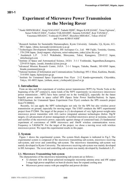
Figure 1 shows <strong>the</strong> experimental system. The system block diagram is indicated in Fig.2. The<br />
experimental system is composed <strong>of</strong> <strong>the</strong> microwave transmitting sub-system, microwave receiving<br />
sub-system, and rover and controlling sub-system. The microwave transmitting sub-system was<br />
mainly developed in Kyo<strong>to</strong> University. The microwave receiving sub-system was mainly developed<br />
in IHI Aerospace. The rover and controlling sub-system was mainly developed by Jisedaitech L.P..<br />
2.1. <strong>Microwave</strong> Transmitting Sub-system<br />
The characteristics <strong>of</strong> <strong>the</strong> microwave transmitting sub-system are as follows ;<br />
• 32 element AIA with linear polarized rectangular microstrip antenna array and 4W output<br />
3-stage high power amplifiers on bent di-electric base for expand cooling area<br />
• <strong>Microwave</strong> power source with pre-amplifier and power dividers<br />
ISBN: 978-4-88552-223-9 C3055©IEICE 648
Transmitting Antenna<br />
Array<br />
Rectenna Array<br />
<strong>Power</strong><br />
Source<br />
<strong>Microwave</strong> <strong>Power</strong><br />
<strong>Transmission</strong><br />
<strong>Rover</strong><br />
Controller<br />
(Antenna, Command<br />
Receiver/Controller)<br />
Command Controller<br />
Fig.1 <strong>Experiment</strong>al System <strong>of</strong> MPT for <strong>Moving</strong> <strong>Rover</strong><br />
<br />
<strong>Power</strong><br />
Source<br />
Current Moni<strong>to</strong>r<br />
<br />
<br />
Signal<br />
Source<br />
Temperature<br />
Moni<strong>to</strong>r<br />
Transmitter<br />
Transmitting Antenna<br />
Target Detecting<br />
System<br />
<strong>Microwave</strong><br />
<strong>Power</strong><br />
Pilot<br />
Signal<br />
Receiver<br />
Rectenna Array<br />
Pilot Signal<br />
(Supersonic) Source<br />
<strong>Power</strong><br />
Controller<br />
Battery<br />
Recorder<br />
<strong>Rover</strong><br />
Command<br />
Transmitter<br />
Wireless<br />
Signal<br />
Anechoic Chamber<br />
ON/OFF<br />
SW<br />
Moni<strong>to</strong>r<br />
(PC)<br />
Fig.2 Block Diagram<br />
Move/S<strong>to</strong>p<br />
Command<br />
Controller<br />
(PC)<br />
Outside<br />
• Fans for cooling<br />
• DC <strong>Power</strong> controller for FETs<br />
• DC power source for all elements<br />
AIA is suitable for small and light weight microwave transmitter because <strong>the</strong> AIA is all integrated<br />
antenna and circuits. Figure 3 shows developed microwave transmitting sub-system with 32 AIAs<br />
<strong>of</strong> approximately 120W 5.8GHzCW output. Total weight <strong>of</strong> <strong>the</strong> 120W system is approximately 4kg<br />
and power-weight-ratio is approximately 33.3g/W. This power-weight-ratio is lightest in <strong>the</strong><br />
previous microwave power transmitter with semi-conduc<strong>to</strong>rs. The volume <strong>of</strong> <strong>the</strong> sub-system is<br />
0.0544 x 10 -3 m 3 (0.17 x 0.12 x 0.32 m). Beam pattern is shown in Fig.4.<br />
2.2. <strong>Microwave</strong> Receiving Sub-system<br />
The microwave receiving sub-system is designed and developed as following specifications ;<br />
• Rectenna arrays on 3 panels on which rectennas are connected in parallel and 3 panels are<br />
connected in series<br />
• Stabilized 6V DC output <strong>of</strong> rectennas through DC/DC converter for higher efficient<br />
rectifying <strong>of</strong> <strong>the</strong> rectenna<br />
• Lead s<strong>to</strong>rage battery for buffer <strong>of</strong> change <strong>of</strong> connected load (DC mo<strong>to</strong>r)<br />
Figure 5 shows <strong>the</strong> developed rectenna array and power controller.<br />
649
Fig. 3 Developed microwave transmitting sub-system with 32 AIAs n bent di-electric base for<br />
expand cooling area<br />
0<br />
(a) E-plane<br />
32 素 子 H 面 アンテナパターン<br />
0<br />
(b) H-plane<br />
32 素 子 E 面 アンテナパターン<br />
-5<br />
-5<br />
-10<br />
-10<br />
-15<br />
-15<br />
Gain(dB)<br />
-20<br />
理 Theory 論 値<br />
実 <strong>Experiment</strong> 測 値<br />
Gain(dB)<br />
-20<br />
理 Theory 論 値<br />
実 <strong>Experiment</strong> 測 値<br />
-25<br />
-25<br />
-30<br />
-30<br />
-35<br />
-35<br />
-40<br />
-40<br />
-90 -60 -30 0 30 60 90<br />
-90 -60 -30 0 30 60 90<br />
角 度 (θ)<br />
角 度 (θ)<br />
θ<br />
θ<br />
Fig.4 Beam Pattern <strong>of</strong> 32 AIA array<br />
Fig. 5 Developed rectenna array and power controller<br />
2.3. <strong>Rover</strong> and Controlling Sub-system<br />
This sub-system is composed with rover and target detecting system with supersonic wave and<br />
small turn table. Figure 6 shows <strong>the</strong> rover with recorder, micro computer for controlling, battery,<br />
and rectenna array. The weight without rectenna array is approximately 10 kg. It has line trace<br />
function and it can move au<strong>to</strong>matically on <strong>the</strong> fixed line.<br />
The turn table can chase <strong>the</strong> position <strong>of</strong> <strong>the</strong> rover with <strong>the</strong> supersonic wave from <strong>the</strong> rover. This<br />
system is on <strong>the</strong> market for home video camera.<br />
2. <strong>Experiment</strong><br />
We have succeeded in moving <strong>the</strong> rover with chasing microwave power. Figure 7 shows <strong>the</strong><br />
experimental setup. Figure 8 indicates <strong>the</strong> power his<strong>to</strong>ry during <strong>the</strong> power transmission. Total<br />
650
power <strong>of</strong> microwave power feed/battery consumption is increased as time goes by and it indicates<br />
that transmitted microwave power is larger than <strong>the</strong> consumption in <strong>the</strong> moving rover. Therefore,<br />
<strong>the</strong>oretically, <strong>the</strong> rover can move only with microwave power.<br />
Fig. 6 <strong>Rover</strong><br />
2mφ <strong>Moving</strong><br />
<strong>Rover</strong> S<strong>to</strong>ps<br />
Charged <strong>Power</strong> [Asec]<br />
<strong>Rover</strong> Moves<br />
MPT S<strong>to</strong>ps<br />
<strong>Rover</strong> S<strong>to</strong>ps<br />
MPT Re-starts<br />
Fig. 7 <strong>Experiment</strong>al Setup<br />
MPT Starts<br />
Time[sec]<br />
Fig.8 Time Dependence <strong>of</strong> Total power <strong>of</strong><br />
microwave power feed/battery consumption<br />
3. Conclusion<br />
We developed experimental system <strong>of</strong> microwave power transmission <strong>to</strong> <strong>the</strong> moving rover. We<br />
achieved 33.3g/W <strong>of</strong> 5.8GHz 120WCW 32 AIAs, (2) advancement <strong>of</strong> power management <strong>of</strong><br />
rectenna with DC/DC converter and buffer battery, (3) successfully coexistence <strong>of</strong> 100W<br />
microwave and 10mW wireless communication waves. These results force <strong>the</strong> MPT technology <strong>to</strong><br />
next step and finally <strong>to</strong> SPS.<br />
Acknowledgments<br />
This study was subsidized by <strong>the</strong> Japan Keirin Association through its Promotion Funds from<br />
KEIRIN RACE and was supported by <strong>the</strong> Mechanical Social Systems Foundation and <strong>the</strong> Ministry<br />
<strong>of</strong> Economy, Trade and Industry.<br />
<strong>Experiment</strong> in <strong>the</strong> present study was carried out with <strong>the</strong> METLAB system <strong>of</strong> Research Institute<br />
for Sustainable Humanosphere (RISH) at Kyo<strong>to</strong> University as a collaborative research project<br />
conducted by Institute for Unmanned Space <strong>Experiment</strong> Free Flyer (USEF).<br />
References<br />
[1] Tesla, N., “The transmission <strong>of</strong> electric energy without wires”, The thirteenth Anniversary<br />
Number <strong>of</strong> <strong>the</strong> Electrical World and Engineer, March 5, 1904<br />
[2] Brown, W. C., “The His<strong>to</strong>ry <strong>of</strong> <strong>Power</strong> <strong>Transmission</strong> by Radio Waves”, IEEE Trans. MTT, Vol.<br />
32, No. 9, pp.1230-1242, 1984<br />
[3] Matsumo<strong>to</strong>, H., “Research on Solar <strong>Power</strong> Station and <strong>Microwave</strong> <strong>Power</strong> <strong>Transmission</strong> in<br />
Japan : Review and Perspectives”, IEEE <strong>Microwave</strong> Magazine, No.12, pp.36-45, 2002<br />
[4] Mihara, S., T. Sai<strong>to</strong>, Y. Kobayashi, and H. Kanai, “Activities Results <strong>of</strong> <strong>Experiment</strong>s for Space<br />
Solar <strong>Power</strong> Systems at USEF”, Proc. <strong>of</strong> IAC, CD-ROM IAC-06-C3.3.2, 2006<br />
651