MightyOhm Geiger Counter Kit Assembly Instructions
MightyOhm Geiger Counter Kit Assembly Instructions
MightyOhm Geiger Counter Kit Assembly Instructions

Create successful ePaper yourself
Turn your PDF publications into a flip-book with our unique Google optimized e-Paper software.
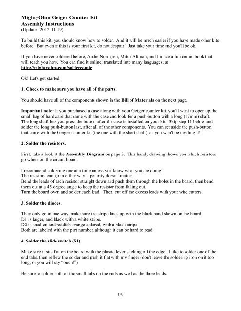
<strong>MightyOhm</strong> <strong>Geiger</strong> <strong>Counter</strong> <strong>Kit</strong><br />
<strong>Assembly</strong> <strong>Instructions</strong><br />
(Updated 2012-11-19)<br />
To build this kit, you should know how to solder. And it will be much easier if you have made other kits<br />
before. But even if this is your first kit, do not despair! Just take your time and you'll be ok.<br />
If you have never soldered before, Andie Nordgren, Mitch Altman, and I made a fun comic book that<br />
will teach you how. You can find it online, translated into many languages, at<br />
http://mightyohm.com/soldercomic<br />
Ok! Let's get started.<br />
1. Check to make sure you have all of the parts.<br />
You should have all of the components shown in the Bill of Materials on the next page.<br />
Important note: If you purchased a case along with your <strong>Geiger</strong> counter kit, you'll want to open up the<br />
small bag of hardware that came with the case and look for a push-button with a long (17mm) shaft.<br />
The long shaft lets you press the button after the case is installed on your kit. Skip step 11 below and<br />
solder the long push-button last, after all of the other components. You can set aside the push-button<br />
that came with the <strong>Geiger</strong> counter kit (the one with the short shaft), as you won't be needing it!<br />
2. Solder the resistors.<br />
First, take a look at the <strong>Assembly</strong> Diagram on page 3. This handy drawing shows you which resistors<br />
go where on the circuit board.<br />
I recommend soldering one at a time unless you know what you are doing!<br />
The resistors can go in either way – polarity doesn't matter.<br />
Bend the leads of each resistor straight down and push them through the holes in the board, then bend<br />
them out at a 45 degree angle to keep the resistor from falling out.<br />
Turn the board over, and solder each lead. Then, cut off the excess leads with your wire cutters.<br />
3. Solder the diodes.<br />
They only go in one way, make sure the stripe lines up with the black band shown on the board!<br />
D1 is larger, and black with a white stripe.<br />
D2 is smaller, and reddish-orange colored, with a black stripe.<br />
Both are labeled with the part number, although it can be hard to read.<br />
4. Solder the slide switch (S1).<br />
Make sure it sits flat on the board with the plastic lever sticking off the edge. I like to solder one of the<br />
end tabs, then reflow the solder and push it flat with my finger (don't leave the soldering iron on it too<br />
long, or you will say “ouch!”)<br />
Be sure to solder both of the small tabs on the ends as well as the three leads.<br />
1/8
<strong>Geiger</strong> <strong>Counter</strong> <strong>Kit</strong> - Bill of Materials<br />
Qty Symbol Name<br />
1 Printed Circuit Board (PCB)<br />
1 U1 ATtiny2313 Microcontroller (20 pin IC)<br />
1 U2 555 Timer (8 pin IC)<br />
1 X1 Ceramic resonator (orange or blue with 3 leads, marked 8.00M, 8.0MC, or 8.00S)<br />
1 LS1 Piezo speaker (round, black, with a hole in the middle)<br />
1 Q1 FJN3303F transistor (marked J3303)<br />
2 Q2,Q3 2N3904 transistors (marked 3904)<br />
1 D1 1N4937 diode (the larger, black diode with a white stripe)<br />
1 D2 1N914 or 1N4148 diode (the smaller, reddish orange diode with a black stripe)<br />
1 LED1 Red LED<br />
1 R8 15 Ohm resistor (brown-green-black-gold)<br />
1 R11 100 Ohm resistor (brown-black-brown-gold)<br />
1 R6 330 Ohm resistor (orange-orange-brown-gold)<br />
1 R5 1K Ohm resistor (brown-black-red-gold)<br />
2 R3,R10 10K Ohm resistors (brown-black-orange-gold)<br />
1 R4 22K Ohm resistor (red-red-orange-gold)<br />
2 R1,R7 100K Ohm resistors (brown-black-yellow-gold)<br />
1 R9 220K Ohm resistor (red-red-yellow-gold)<br />
1 R2 4.7M Ohm resistor (yellow-violet-green-gold)<br />
1 VR1 10 Ohm variable resistor (blue with a white screw in the middle)<br />
1 L1 10mH inductor (the small black cylinder marked 103 on top)<br />
1 C2 220pF capacitor (marked 221K)<br />
1 C3 1nF capacitor (tiny, 5mm lead spacing, marked 102)<br />
1 C1 0.01uF capacitor (the biggest disc, marked 103M)<br />
1 C4 0.1uF capacitor (tiny, 2.5mm lead spacing, marked 104)<br />
1 C5 100uF electrolytic capacitor (black cylinder marked 100uF)<br />
1 S1 Slide switch<br />
1 S2 Push button (microswitch) with short shaft (for kits purchased without a case)<br />
2 J1, J2 <strong>Geiger</strong> tube holders (the clips)<br />
1 B1 Battery Holder for 2xAAA batteries<br />
1 J5 2x3 row header pins (for the ICSP connector)<br />
1 J6,J7 a row of header pins (to break into 1x3 and 1x6, you may have some left over)<br />
1 IC socket – 20 pins<br />
1 IC socket – 8 pins<br />
1 Small screw for the battery holder<br />
1 Small nut<br />
and, if you ordered a kit with a <strong>Geiger</strong> tube, you should also have:<br />
1 <strong>Geiger</strong>-Müller Tube (cylindrical tube wrapped in foam or bubble wrap)<br />
Note: The case for this kit (if you purchased one) has a separate parts list, shown on the last page of<br />
these instructions. If you are planning to assemble the case, you should open up the small bag of parts<br />
that came with it and find the small pushbutton with the long shaft. When you get to step 19 below, use<br />
the long pushbutton instead of the ordinary (short) one that came with your <strong>Geiger</strong> <strong>Counter</strong> kit. That<br />
way you’ll be able to push the button after the case is installed!<br />
2/8
<strong>Geiger</strong> <strong>Counter</strong> <strong>Kit</strong> – <strong>Assembly</strong> Diagram<br />
3/8
5. Solder capacitors C3 and C4.<br />
Both of these capacitors are very small. C4 goes next to U2 and is marked 104. It is the very tiny<br />
capacitor with narrowly spaced leads (2.5mm). C3 is marked 102 and has wider leads (5mm spacing).<br />
6. Solder the variable resistor (VR1).<br />
This part is easy to find – it's blue with 3 leads.<br />
7. Solder the transistors.<br />
First, solder Q1. It is marked J3303. Make sure the flat spot of the transistor lines up with the markings<br />
on the PCB. You will need to bend the leads slightly to get them into the holes. Don't push the<br />
transistors all the way down against the PCB – leave a few mm gap.<br />
Solder Q2 and Q3, marked 3904. Make sure you put them in the right way!<br />
8. If you want to log data or hack the kit, install the headers J5, J6, and J7.<br />
J5 is the double-row header (2 rows x 3 pins)<br />
J6 and J7 are a single row – you can break the supplied header strip into 1 strip of 3 and 1 strip of 6 pins.<br />
You can break off the strips with pliers or use your wire cutters – be careful.<br />
When soldering the headers, it's a good idea to solder one pin and then make sure the header is straight,<br />
then solder the rest of the pins.<br />
9. Solder capacitor C2 and the ceramic resonator X1.<br />
C2 is marked 221K and sits up above the PCB a little bit.<br />
X1 is marked 8.00M or 8.0MC and has three leads.<br />
Both of these can be installed in either direction – they are non-polarized.<br />
10. Solder the IC sockets for U1 and U2.<br />
These pop into place and are easy to solder. Make sure the notch in the socket aligns with the notch in<br />
the silkscreen on the PCB. You don't need to clip the leads, they are already very short.<br />
11. Solder the inductor (L1).<br />
L1 is the black cylinder marked 103. It can go in either way.<br />
12. Solder the piezo (LS1).<br />
This is the large, short cylinder with a hole in the middle. It can go in either way.<br />
13. Solder the electrolytic capacitor C5.<br />
C5 is the large, black capacitor with a white stripe on one side – that side is negative and goes away<br />
from the + symbol. Make sure you install this one in the right direction – it's polarized. Push it all the<br />
way down against the PCB – you might have to wiggle the leads a little bit.<br />
4/8
14. Solder the tube holder clips (J1 and J2)<br />
These are the small metal clips. J1 and J2 are the furthest apart, this is for the SBM-20 <strong>Geiger</strong> tube,<br />
which is longest. For other tubes, you can put the right clip into different positions.<br />
I solder one lead of the clips, make sure it's straight, and then solder the other lead.<br />
15. Solder the LED.<br />
The LED only goes in one way. It will sit up a bit above the PCB. The long lead goes into the hole<br />
marked +, and the flat spot on the side of the LED goes towards the other lead (just like the drawing on<br />
the PCB). Solder one lead, check to make sure the LED is sitting straight, and then solder the other lead.<br />
16. Solder C1, the large ceramic disc cap.<br />
This one can go in either way.<br />
17. Solder the battery holder (B1).<br />
Make sure it's straight, cut off the excess leads (watch your eyes!), and insert the small screw into the<br />
hole in the middle. Flip the board over and install the small nut. You'll need a small screwdriver, but<br />
you can use your fingers to hold the nut.<br />
18. Install the Integrated Circuits (U1 and U2).<br />
You will need to bend the IC pins inward slightly to get them to fit into the sockets. Be careful! You<br />
don't want to push too hard and wind up with a pin bent and sticking out of the socket – maybe into your<br />
finger!<br />
Make sure the notch and/or small dot on each IC goes towards the notch in the socket (on the left if you<br />
are looking at the board with the text right side up). The ATtiny2313 has a large dot and a small dot on<br />
top, the small dot goes closest to the notch (pin 1).<br />
The TLC555CP goes into the socket for U1.<br />
The ATTINY2313V goes into the socket for U2.<br />
Handle these parts carefully, they are static sensitive.<br />
19. Solder the push-button (S2).<br />
Important: If you purchased your kit with a case, use the long pushbutton that came with the case<br />
instead of the ordinary (short) one that is included with the <strong>Geiger</strong> <strong>Counter</strong> kit!<br />
The push-button can go in either way. No need to clip the leads on this either.<br />
20. Install the <strong>Geiger</strong> Tube<br />
Important! First, use a pair of needle-nose pliers to bend the tube clips apart slightly, so they aren't so<br />
tight on the tube. Then carefully insert the tube. It is polarized! Make sure the + mark or CBM20<br />
writing is on the left side of the board, closest to the tube clip marked +.<br />
5/8
Don't squeeze or push too hard on the tube, or drop it – it is very fragile. If the clips are too tight, stop<br />
and bend them outwards slightly, then try again.<br />
Don't force the tube into the clips (you will crush it)!!!<br />
21. Test it!<br />
Warning: This kit is capable of generating high voltages (300-600V). Don't touch any part of the circuit<br />
(particularly the bottom of the PCB) while it is on! The current is low, so while the potential for injury<br />
is low, it may startle you and cause you to drop your kit (and break your <strong>Geiger</strong> tube!)<br />
Make sure the switch is off (away from the ON position) and adjust VR1 all the way counter-clockwise.<br />
Insert two AAA batteries in the battery holder and turn on S1.<br />
Listen for clicks and watch the LED. SLOWLY rotate VR1 clockwise until you hear clicks. Once you<br />
start to hear clicks, rotate VR1 about 45 degrees more and stop.<br />
If you have a multimeter with a very high input impedance (1GOhm), you can measure the voltage from<br />
ground to TP2 – it should be about 400V. If you have an ordinary digital multimeter, you can get a<br />
1GOhm resistor and put it in series with your DMM, then multiply the reading by the ratio [1000 / (the<br />
internal resistance of your DMM in Megaohms)] More info: http://ea4eoz.ure.es/hvprobe.html<br />
How to use it!<br />
Easy, turn on the switch and listen for clicks! Watch the LED, it will flash every time a beta particle or<br />
gamma ray hits the tube! (Note: The tube that comes with the kit is not sensitive to alpha particles.)<br />
If you get tired of hearing the clicks, you can push the button S2 to MUTE the sound.<br />
The PULSE connector (J6) has the following pinout:<br />
1. VCC (nominally 3V)<br />
2. pulse output – a short (100us) active high pulse every time the <strong>Geiger</strong> tube fires<br />
3. GND<br />
More information, design files, source code: http://mightyohm.com/geiger<br />
Logging:<br />
To connect your computer to the serial port (J7), you will need a USB-serial converter that operates at<br />
3.3V TTL levels. The serial header is set up to work with the common FTDI-232R-3V3 serial cable.<br />
Data is sent over the serial port at 9600 baud, 8N1.<br />
The data is reported in comma separated value (CSV) format:<br />
CPS, #####, CPM, #####, uSv/hr, ###.##, SLOW|FAST|INST<br />
There are three modes. Normally, the sample period is LONG_PERIOD (default 60 seconds). This is<br />
SLOW averaging mode. If the last five measured counts exceed a preset threshold, the sample period<br />
switches to SHORT_PERIOD seconds (default 5 seconds). This is FAST mode, and is more responsive<br />
but less accurate. Finally, if CPS > 255, we report CPS*60 and switch to INST mode, since we can't<br />
store data in the (8-bit) sample buffer.<br />
6/8
Troubleshooting<br />
What if you finish assembling your kit, and it doesn't work? Don't panic!<br />
When you turn the kit on, you should hear a faint high pitched whine from the speaker. This whine tells<br />
you that the HV supply is working.<br />
First, make sure the batteries are fresh (or fully charged). Note that some batteries may occasionally get<br />
stuck in the battery holder and won't make contact with both terminals. Try pushing each battery away<br />
from the spring (negative) side of its compartment so that the positive end makes contact with the metal<br />
terminal on the holder. If you have a multimeter, make sure you read about 3V across the battery pack<br />
terminals on the back side of the PCB.<br />
If your kit still isn't working, the first step in debugging is to check all of your solder joints. Reflow and<br />
add more solder to any joints that look cracked and dull or don't have enough solder on the pad - the<br />
solder should make a nice hershey-kiss shape on the pads, with the lead sticking up through the top of<br />
the solder joint. The places I usually see bad solder joints the most are the terminals of the battery pack<br />
and the piezo speaker. Inspect for shorts between pads as well, it is easy to bridge two pads with a blob<br />
of solder.<br />
Double-check that the transistors and diodes are installed in the correct direction.<br />
Make sure FJN3303F is installed in the spot for Q1, and the 2N3904 transistors are installed in Q2 and<br />
Q3. If the transistors are in the wrong spot, the kit won't work!<br />
If you use a piece of wire (or your fingers) to short across the + and - clips for the tube you should get a<br />
click and an LED flash. Try this with the tube installed, and then removed, you should get a click in both<br />
cases. If not, check your component placement and solder joints again.<br />
If you need help:<br />
Visit the support forums at http://mightyohm.com/forum/ and do a search. Maybe someone else has<br />
seen your problem before? If not, post a new topic and ask for help!<br />
If there is a problem with your order, send an e-mail to support@mightyohm.com.<br />
***** WARNING *****<br />
This <strong>Geiger</strong> <strong>Counter</strong> kit is for EDUCATIONAL PURPOSES ONLY. Don't even think about using<br />
it to monitor radiation in life-threatening situations, or in any environment where you may expose<br />
yourself to dangerous levels of radiation. Don't rely on the collected data to be an accurate<br />
measure of radiation exposure! Be safe!<br />
7/8
Case <strong>Assembly</strong> <strong>Instructions</strong><br />
1. Check to see if you have all the parts<br />
Empty the case kit on your work surface. You should have all of the following parts:<br />
Qty Name<br />
1 Top Plate<br />
1 Bottom Plate<br />
4 Short hex standoffs<br />
4 Longer round standoffs<br />
8 Screws<br />
8 Lock-washers<br />
1 Push-button with a long (17mm) shaft<br />
2. Install the standoffs<br />
The longer round standoffs go on top of the board, and the shorter hex standoffs screw into them through<br />
the bottom of the PCB. Repeat for all four corners of the board. Finger tight is ok, just make them snug.<br />
3. Remove the paper backing from the top and bottom plates<br />
Use your fingernail, not anything metallic or sharp, because the acrylic scratches fairly easily.<br />
4. Install the bottom cover plate<br />
Secure the bottom plate to the hex standoffs with a screw and lock-washer at each corner. Tighten the<br />
screws until they are snug. Don’t over-tighten the screws – if you do, you will crack the acrylic.<br />
5. Install the top cover plate<br />
Turn the kit over and install the top plate with the remaining screws and lock-washers. Don’t overtighten<br />
the screws!<br />
You're done!<br />
Cleaning the case:<br />
Use a soft cloth (microfiber is best). Gently wipe the case clean, being careful not to scratch it. If<br />
necessary, you can remove the cover plates from the <strong>Geiger</strong> <strong>Counter</strong> and wash them in soap and warm<br />
water. Don't ever use alcohol or ammonia-based cleaners (Windex) as they will damage the acrylic and<br />
may cause it to crack.<br />
8/8