
Create successful ePaper yourself
Turn your PDF publications into a flip-book with our unique Google optimized e-Paper software.
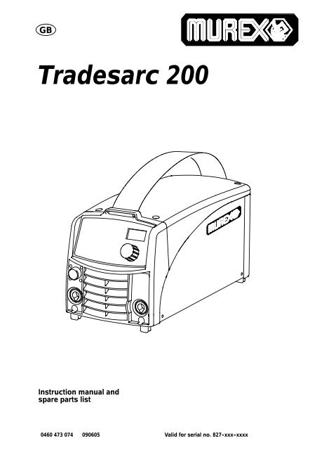
GB<br />
<strong>Tradesarc</strong> <strong>200</strong><br />
Instruction manual and<br />
spare parts list<br />
0460 473 074 090605<br />
Valid for serial no. 827 -xxx -xxxx
1 DIRECTIVE ........................................................ 3<br />
2SAFETY...........................................................<br />
3<br />
3 INTRODUCTION ................................................... 4<br />
3.1 Equipment ................................................................ 5<br />
3.2 Control panel ............................................................. 5<br />
4 TECHNICAL DATA ................................................. 5<br />
5 INSTALLATION .................................................... 6<br />
5.1 Location .................................................................. 6<br />
5.2 Mains power supply ........................................................ 6<br />
6 OPERATION ....................................................... 7<br />
6.1 PFC -- Power factor correction .............................................. 7<br />
6.2 Connections and control devices ............................................ 7<br />
6.3 Connection of welding and return cable ....................................... 7<br />
6.4 Overheating protection ..................................................... 7<br />
6.5 MMA welding ............................................................. 8<br />
6.6 TIG welding ............................................................... 8<br />
6.7 Remote control unit ........................................................ 9<br />
7 MAINTENANCE .................................................... 9<br />
7.1 Inspection and cleaning .................................................... 9<br />
8 FAULT -TRACING .................................................. 10<br />
8.1 Fault codes ............................................................... 10<br />
9 CONTROL PANEL .................................................. 10<br />
10 MMA WELDING .................................................... 12<br />
10.1 Settings .................................................................. 12<br />
10.2 Symbol and Function explanations ........................................... 12<br />
10.3 Hidden functions MMA welding .............................................. 13<br />
11 TIG WELDING ..................................................... 13<br />
11.1 Settings .................................................................. 13<br />
11.2 Symbol and Function explanations ........................................... 14<br />
12 WELDING DATA MEMORY .......................................... 14<br />
13 FAULT CODES ..................................................... 15<br />
13.1 Fault code descriptions ..................................................... 15<br />
14 ORDERING SPARE PARTS .......................................... 16<br />
15 DISMANTLING AND SCRAPPING ................................... 16<br />
DIAGRAM ............................................................ 18<br />
SPARE PARTS LIST ................................................... 21<br />
ACCESSORIES ....................................................... 26<br />
Rights reserved to alter specifications without notice.<br />
TOCe<br />
- 2 -
GB<br />
1 DIRECTIVE<br />
DECLARATION OF CONFORMITY<br />
<strong>Murex</strong> Welding Products Ltd, EN8 7TF England, gives its unreserved guarantee that welding power<br />
source <strong>Tradesarc</strong> <strong>200</strong> from serial number 827 (<strong>200</strong>8 w 27) are constructed and tested in compliance<br />
with the standard EN 60974--1 and EN 60974--10 (Class A) in accordance with the requirements of<br />
directive (<strong>200</strong>6/95/EC) and (<strong>200</strong>4/108/EEC).<br />
-- -- -- -- -- -- -- -- -- -- -- -- -- -- -- -- -- -- -- -- -- -- -- -- -- -- -- -- -- -- -- -- -- -- -- -- -- -- -- -- -- -- -- -- -- -- -- -- -- -- -- -- -- -- -- -- -- -- -- -- -- -- -- --------<br />
On behalf of <strong>Murex</strong> Welding Products Ltd.<br />
Laxå <strong>200</strong>8--08--28<br />
Kent Eimbrodt<br />
Global Director<br />
Equipment and Automation<br />
2 SAFETY<br />
Manufactured by ESAB AB, Welding Equipment<br />
SE--695 81 Laxå Sweden<br />
Users of welding equipment have the ultimate responsibility for ensuring that anyone who works on<br />
or near the equipment observes all the relevant safety precautions. Safety precautions must meet<br />
the requirements that apply to this type of welding equipment. The following recommendations<br />
should be observed in addition to the standard regulations that apply to the workplace.<br />
All work must be carried out by trained personnel well--acquainted with the operation of the welding<br />
equipment. Incorrect operation of the equipment may lead to hazardous situations which can result<br />
in injury to the operator and damage to the equipment.<br />
1. Anyone who uses the welding equipment must be familiar with:<br />
S its operation<br />
S location of emergency stops<br />
S its function<br />
S relevant safety precautions<br />
S welding<br />
2. The operator must ensure that:<br />
S no unauthorized person is stationed within the working area of the equipment when it is<br />
started up.<br />
S no--one is unprotected when the arc is struck<br />
3. The workplace must:<br />
S be suitable for the purpose<br />
S be free from drafts<br />
4. Personal safety equipment<br />
S Always wear recommended personal safety equipment, such as safety glasses, flame--proof<br />
clothing, safety gloves.<br />
S Do not wear loose--fitting items, such as scarves, bracelets, rings, etc., which could become<br />
trapped or cause burns.<br />
5. General precautions<br />
S Make sure the return cable is connected securely.<br />
S Work on high voltage equipment may only be carried out by a qualified electrician.<br />
S Appropriate fire extinquishing equipment must be clearly marked and close at hand.<br />
S Lubrication and maintenance must not be carried out on the equipment during operation.<br />
CAUTION!<br />
This product is solely intended for arc welding.<br />
bh37d1em<br />
- 3 -
GB<br />
WARNING<br />
Arc welding and cutting can be injurious to yourself and others. Take precausions when welding.<br />
Ask for your employer’s safety practices which should be based on manufacturers’ hazard data.<br />
ELECTRIC SHOCK - Can kill<br />
S Install and earth the welding unit in accordance with applicable standards.<br />
S Do not touch live electrical parts or electrodes with bare skin, wet gloves or wet clothing.<br />
S Insulate yourself from earth and the workpiece.<br />
S Ensure your working stance is safe.<br />
FUMES AND GASES - Can be dangerous to health<br />
S Keep your head out of the fumes.<br />
S Use ventilation, extraction at the arc, or both, to take fumes and gases away from your breathing zone<br />
and the general area.<br />
ARC RAYS - Can injure eyes and burn skin.<br />
S Protect your eyes and body. Use the correct welding screen and filter lens and wear protective<br />
clothing.<br />
S Protect bystanders with suitable screens or curtains.<br />
FIRE HAZARD<br />
S Sparks (spatter) can cause fire. Make sure therefore that there are no inflammable materials nearby.<br />
NOISE - Excessive noise can damage hearing<br />
S Protect your ears. Use earmuffs or other hearing protection.<br />
S Warn bystanders of the risk.<br />
MALFUNCTION - Call for expert assistance in the event of malfunction.<br />
Read and understand the instruction manual before installing or operating.<br />
PROTECT YOURSELF AND OTHERS!<br />
<strong>Murex</strong> can provide you with all necessary welding protection and accessories.<br />
WARNING!<br />
Do not use the power source for thawing frozen pipes.<br />
CAUTION!<br />
Read and understand the instruction manual before<br />
installing or operating.<br />
CAUTION!<br />
Class A equipment is not intended for use in residential locations where<br />
the electrical power is provided by the public low -voltage supply<br />
system. There may be potential difficulties in ensuring electromagnetic<br />
compatibility of class A equipment in those locations, due to conducted<br />
as well as radiated disturbances.<br />
3 INTRODUCTION<br />
<strong>Tradesarc</strong> <strong>200</strong> is a welding current power source intended for use with coated<br />
electrodes (MMA welding) and TIG welding.<br />
Accessories for the product can be found on page 26.<br />
bh37d1em<br />
- 4 -
GB<br />
3.1 Equipment<br />
<strong>Tradesarc</strong> <strong>200</strong> issuppliedwitha3mweldingcable,returncable,3mmainscable<br />
and an instruction manual for power source and control panel.<br />
3.2 Control panel<br />
Welding process parameters are controlled via the control panel, see page 10.<br />
4 TECHNICAL DATA<br />
Mains voltage<br />
Primary current<br />
I max TIG<br />
I max MMA<br />
Mains supply<br />
No -load power demand when in the<br />
energy--saving mode, 6.5 min. after welding<br />
Voltage/current range, MMA<br />
Voltage/current range TIG<br />
Permissible load at MMA<br />
25% duty cycle<br />
60% duty cycle<br />
100% duty cycle<br />
Permissible load at TIG<br />
20% duty cycle<br />
60% duty cycle<br />
100% duty cycle<br />
Power factor at maximum current<br />
TIG<br />
MMA<br />
Efficiency at maximum current<br />
TIG<br />
MMA<br />
Open -circuit voltage MMA / TIG<br />
without VRD<br />
with VRD<br />
Operating temperature<br />
Transportation temperature<br />
Constant A -weighted sound pressure<br />
Dimensions, l x b x h<br />
Weight<br />
<strong>Tradesarc</strong> <strong>200</strong><br />
230 V, 1 μ 50/60 Hz<br />
24 A<br />
25 A<br />
Z max 0.31 ohm<br />
30 W<br />
4 A /20 V -- 170 A /26.8 V<br />
3 -- 220 A<br />
170 A / 26.8 V<br />
130 A / 25.2 V<br />
110A/24.4V<br />
220 A / 18.8 V<br />
150 A / 16.0 V<br />
110A/14.4V<br />
0.99<br />
0.99<br />
75%<br />
81%<br />
Enclosure class IP 23<br />
Application class<br />
55 -- 60 V<br />
GB<br />
Application class<br />
The symbol indicates that the power source is designed for use in areas with increased<br />
electrical hazard.<br />
Mains supply, Z max<br />
Maximum permissible line impedance of the network in accordance with IEC 61000--3--11.<br />
5 INSTALLATION<br />
The installation must be executed by a professional.<br />
Note!<br />
Mains supply requirements<br />
High power equipment may, due to the primary current drawn from the mains supply, influence the<br />
power quality of the grid. Therefore connection restrictions or requirements regarding the<br />
maximum permissible mains impedance or the required minimum supply capacity at the interface<br />
point to the public grid may apply for some types of equipment (see technical data). In this case it<br />
is the responsibility of the installer or user of the equipment to ensure, by consultation with the<br />
distrubution network operator if necessary, that the equipment may be connected.<br />
5.1 Location<br />
Position the power source such that its cooling air inlets and outlets are not<br />
obstructed.<br />
5.2 Mains power supply<br />
Check that the welding power source is connected to<br />
the correct voltage and that the correct fuse size is used.<br />
A protective earth connection must be made in accordance<br />
with regulations<br />
Location of rating plate<br />
5.2.1 Recommended fuse sizes and minimum cable area<br />
Mains voltage<br />
<strong>Tradesarc</strong> <strong>200</strong><br />
230 V ¦10 %, 1--phase<br />
Mains frequency<br />
50--60 Hz<br />
Mains cable, area 3G2.5 mm 2<br />
Phase current I 1eff<br />
14 A<br />
Welding cable, area 16 mm 2<br />
Fuse<br />
anti--surge<br />
type C MCB<br />
16 A<br />
16 A<br />
NOTE!<br />
The cable area and fuse rating above comply with Swedish regulations. Use the<br />
welding power source in accordance with the relevant national regulations.<br />
bh37d1em<br />
- 6 -
GB<br />
6 OPERATION<br />
6.1 PFC - Power factor correction<br />
The <strong>Tradesarc</strong> <strong>200</strong> is 230 V single--phase power sources equipped with a PFC circuit<br />
making it possible to use the full range of the machine on a 16 A fuse. The PFC<br />
also protects the machines against fluctuating mains voltage and makes it safer to<br />
use with a generator. <strong>Tradesarc</strong> <strong>200</strong> can operate with extra long mains cables, over<br />
100 m, giving you a very larger working radius.<br />
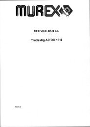
6.2 Connections and control devices<br />
1 Connection (+)<br />
MMA: for return cable or welding cable<br />
TIG: for return cable<br />
4 Connection (--)<br />
MMA: for return cable or welding cable<br />
TIG: for Tig torch l<br />
2 Connection for remote control unit 5 Toggle switch for mains power supply 0 / 1<br />
3 Control panel, see under 3.2 6 Mains cable<br />
6.3 Connection of welding and return cable<br />
The power source has two outputs, a positive terminal (+) and a negative terminal<br />
(--), for connecting welding and return cables. The output to which the welding cable<br />
is connected depends on the type of electrode used. The connecting polarity is<br />
stated on the electrode packaging. Connect the welding cable to the terminal stated<br />
on the electrode packaging.<br />
Connect the return cable to the other output on the power source. Secure the return<br />
cable’s contact clamp to the work piece and ensure that there is good contact<br />
between the work piece and the output for the return cable on the power source.<br />
6.4 Overheating protection<br />
The welding power source has a thermal overload trip which operates if the<br />
temperature becomes too high, interrupting the welding current and lighting a yellow<br />
indicating lamp on the front of the power source. The thermal overload trip resets<br />
automatically when the temperature has fallen.<br />
bh37d1em<br />
- 7 -
GB<br />
6.5 MMA welding<br />
<strong>Tradesarc</strong> <strong>200</strong> gives direct current, and you can weld most metals to alloy and non--<br />
alloy steel, stainless steel and cast iron.<br />
<strong>Tradesarc</strong> <strong>200</strong> allows you to weld most coated electrodes from Ø 1.6 to Ø 3.25.<br />
MMA welding may also be referred to as welding with coated electrodes. Striking the arc<br />
melts the electrode, and its coating forms protective slag.<br />
If, when striking the arc, the tip of the electrode is pressed against the metal, it immediately<br />
melts and sticks to the metal, rendering continued welding impossible.<br />
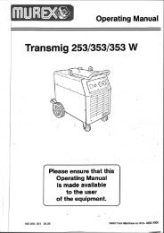
Therefore, the arc has to be struck in the same way that you would light a match.<br />
Quickly strike the electrode against the metal, then raise it so<br />
as to give an appropriate arc length (approx. 2 mm). If the arc<br />
is too long, it will crackle and spit before finally going out completely.<br />
If you are working on a welding bench, check before attempting<br />
to strike the arc that residual waste metal, pieces of electrode<br />
or other objects on the bench do not insulate the part to be<br />
welded.<br />
Once the arc has been struck, move the electrode from left to<br />
right. The electrode must be at an angle of 60˚ to the metal in<br />
relation to the direction of welding.<br />
When you want to weld wide beads, or when you want the weld<br />
to be so thick that you have to weld in a number of layers, however,<br />
you have to use lateral movements.<br />
cmha2p11<br />
cmha2p10<br />
6.6 TIG welding<br />
TIG welding melts the metal of the workpiece, using an arc struck from a tungsten<br />
electrode, which does not itself melt. The weld pool and the electrode are protected<br />
by shielding gas.<br />
TIG welding is particularly useful where high quality is demanded and for welding<br />
thin plate. <strong>Tradesarc</strong> <strong>200</strong> also has good characteristics for TIG welding.<br />
In order to TIG weld <strong>Tradesarc</strong> <strong>200</strong> must be equipped with:<br />
S a TIG torch with gas valve<br />
S a welding gas cylinder (a suitable welding gas)<br />
S a welding gas regulator (suitable gas regulator)<br />
S tungsten electrode<br />
S suitable auxiliary material, if necessary.<br />
bh37d1em<br />
- 8 -
GB<br />
”Live TIG -start”<br />
With “Live TIG start” the arc strikes when the tungsten electrode is brought into<br />
contact with the workpiece and then lifted away from it.<br />
6.7 Remote control unit<br />
The remote control unit is connected to the remote control socket on the power<br />
source.<br />
7 MAINTENANCE<br />
Regular maintenance is important for safe, reliable operation.<br />
Only those persons who have appropriate electrical knowledge (authorized<br />
personnel) may remove the safety plates to connect or carry out service,<br />
maintenance or repair work on welding equipment.<br />
CAUTION!<br />
All guarantee undertakings from the supplier cease to apply if the customer himself<br />
attempts any work in the product during the guarantee period in order to rectify any faults.<br />
7.1 Inspection and cleaning<br />
Power source<br />
Check regularly that the welding power source is not clogged with dirt.<br />
How often and which cleaning methods apply depend on: the welding process, arc<br />
times, placement, and the surrounding environment. It is normally sufficient to blow<br />
down the power source with dry compressed air (reduced pressure) once a year.<br />
Clogged or blocked air inlets and outlets otherwise result in overheating.<br />
TIG torch<br />
The TIG torch’s wear parts should be cleaned and replaced at regular intervals in<br />
order to achieve trouble--free welding.<br />
bh37d1em<br />
- 9 -
GB<br />
8 FAULT -TRACING<br />
Try these recommended checks and inspections before sending for an authorized<br />
service technician.<br />
Type of fault<br />
Corrective action<br />
No arc. S Check that the mains power supply switch is turned on.<br />
S Check that the welding current supply and return cables are<br />
correctly connected.<br />
S Check that the correct current value is set.<br />
S Check to see whether the MCB has tripped.<br />
The welding current is interrupted<br />
during welding.<br />
S Check whether the thermal cut--outs have tripped (indicated<br />
by the orange lamp on the front panel).<br />
S Check the mains power supply fuses.<br />
The thermal cut--out trips frequently.<br />
S Check to see whether the dust filter is clogged.<br />
S Make sure that you are not exceeding the rated data for the<br />
power source (i.e. that the unit is not being overloaded).<br />
Poor welding performance. S Check that the welding current supply and return cables are<br />
correctly connected.<br />
S Check that the correct current value is set.<br />
S Check that the correct electrodes are being used.<br />
S Check the gas flow.<br />
8.1 Fault codes<br />
<strong>Tradesarc</strong> <strong>200</strong> comes with built--in fault monitoring. If a fault occurs, a code is shown<br />
in the display, see page 15.<br />
9 CONTROL PANEL<br />
When mains power is supplied the unit runs a self diagnosis of the<br />
LEDs and the display, the program version is displayed and in this<br />
example the program version is 0.18.<br />
VRD (Voltage Reduction Device)<br />
The VRD function ensures that the open--circuit voltage does not exceed 35 V when<br />
welding is not being carried out. This is indicated by a lit VRD LED. The VRD<br />
function is deactivated when the system senses that welding has started.<br />
If the VRD function is activated and open--circuit voltage exceeds the 35 V limit, this<br />
is indicated by an error message (16) appearing in the display and welding cannot<br />
be started whilst the error message is displayed.<br />
NOTE! The VRD function is not active (LED has gone out) on delivery. Contact an<br />
authorised ESAB service technician to activate the function.<br />
bh37d1em<br />
- 10 -
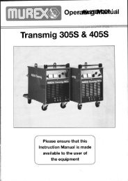
Display<br />
Indication of which parameter is shown in the display (current or percent)<br />
Knob for setting data (current or percent)<br />
Buttons for weld data memory settings. See title 12.<br />
Button for choosing parameters ”Hot start”<br />
or arc pressure ”Arc force”<br />
when MMA welding<br />
Choice of welding method MMA<br />
or TIG<br />
Setting from panel<br />
and connecting remote control unit<br />
Display of VRD function (reduced open--circuit voltage).<br />
bh37d2em<br />
- 11 -
10 MMA WELDING<br />
10.1 Settings<br />
Function Setting range <strong>Tradesarc</strong> <strong>200</strong><br />
Current 4 max 1) x<br />
Active panel OFF or ON x<br />
Remote control unit OFF or ON x<br />
Hot start 0 -- 99% x<br />
Arc force 0 -- 99% x<br />
Drop welding OFF or ON x 2)<br />
VRD -- --<br />
1) The setting range is dependent on the power source used.<br />
2) Hidden function<br />
10.2 Symbol and Function explanations<br />
MMA welding<br />
MMA welding may also be referred to as welding with coated electrodes. Striking the<br />
arc melts the electrode, and its coating forms protective slag.<br />
Setting current<br />
A higher current produces a wider weld pool, with better penetration into the<br />
workpiece.<br />
Active panel<br />
Settings are made from the control panel.<br />
Remote control unit<br />
Settings are made from the remote control unit.<br />
The remote control unit must be connected to the remote control unit socket on the<br />
machine before activation. When the remote control unit is activated the panel is<br />
inactive.<br />
Hot Start<br />
Increases the welding current during a fixed time at the start of the welding process.<br />
Set the value of the hot start current by using the knob. This reduces the risk of<br />
incomplete fusion at the start of the weld.<br />
Arc force<br />
The arc force is important in determining how the current changes in response to a<br />
change in the arc length. A lower value gives a calmer arc with less spatter.<br />
bh37d2em<br />
- 12 -
10.3 Hidden functions MMA welding<br />
There are hidden functions in the control panel.<br />
To access the functions in <strong>Tradesarc</strong> <strong>200</strong>, hold button depressed for 5 seconds.<br />
The display shows a letter and a value. The correct function is selected by pressing<br />
the buttons. The knob is used to change the value of the selected function.<br />
Function letter<br />
C<br />
H<br />
d<br />
Function<br />
Arc Force<br />
Hotstart<br />
Drop welding<br />
To leave the function in <strong>Tradesarc</strong> <strong>200</strong> hold the button depressed for 5<br />
seconds.<br />
Arc force<br />
The arc force is important in determining how the current changes in response to a<br />
change in the arc length. A lower value gives a calmer arc with less spatter.<br />
Hot Start<br />
Increases the welding current during a fixed time at the start of the welding process.<br />
Set the value of the hot start current by using the knob. This reduces the risk of<br />
binding defects at the start of the weld.<br />
Drop welding<br />
Drop welding can be used when welding with stainless electrodes. The function<br />
involves alternately striking and extinguishing the arc in order to achieve better<br />
control of the supply of heat. The electrode needs only to be raised slightly to<br />
extinguish the arc.<br />
11 TIG WELDING<br />
11.1 Settings<br />
Function Setting range <strong>Tradesarc</strong> <strong>200</strong><br />
Current 4 max 1) x<br />
Active panel OFF or ON x<br />
Remote control unit OFF or ON x<br />
VRD -- --<br />
1) The setting range is dependent on the power source used.<br />
bh37d2em<br />
- 13 -
11.2 Symbol and Function explanations<br />
TIG welding<br />
TIG welding melts the metal of the workpiece, using an arc struck from a tungsten electrode,<br />
which does not melt itself. The weld pool and the electrode are protected by<br />
shielding gas.<br />
”LiveTig start”<br />
With “LiveTig start” the arc strikes when the tungsten electrode is brought into<br />
contact with the workpiece and then lifted away from it.<br />
Active panel<br />
Settings are made from the control panel.<br />
Remote control unit<br />
Settings are made from the remote control unit.<br />
The remote control unit must be connected to the remote control unit socket on the<br />
machine before activation. When the remote control unit is activated the panel is<br />
inactive.<br />
12 WELDING DATA MEMORY<br />
Two different welding data programs can be stored in the control panel memory.<br />
Press button or for 5 seconds to store the welding data in the<br />
memory. The welding data is stored when the green indicator lamp starts to flash.<br />
To switch between the different welding data memories press button<br />
or<br />
.<br />
The welding data memory has a back--up so that the settings remain even if the<br />
machine has been switched off.<br />
bh37d2em<br />
- 14 -
13 FAULT CODES<br />
Fault codes are used to indicate that a fault has occurred in the equipment. It is<br />
indicated in the display by an E followed by a fault code number.<br />
If several faults have been detected only the code for the last occurring fault is<br />
displayed. Press any function button or turn the knob to remove the fault indication<br />
from the display.<br />
NOTE! If the remote control unit is activated, deactivate the remote control unit by<br />
pressing<br />
to remove the fault indication.<br />
13.1 Fault code descriptions<br />
The fault codes that the user can correct themselves are given below. If a different<br />
code appears, call a service technician.<br />
Fault<br />
code<br />
E6<br />
E14<br />
E16<br />
E19<br />
Description<br />
High temperature<br />
The thermal overload cut--out has tripped.<br />
The current welding process is stopped and cannot be restarted until the temperature has<br />
fallen.<br />
Action: Check that the cooling air inlets or outlets are not blocked or clogged with dirt.<br />
Check the duty cycle being used, to make sure that the equipment is not being overloaded.<br />
Communication error (bus off)<br />
Serious interference on the CAN bus.<br />
Action: Check that there are no faulty units connected on the CAN bus. Check the cables.<br />
Send for a service technician if the fault persists.<br />
High open -circuit voltage<br />
Open circuit voltage has been too high.<br />
Action: Turn off the mains power supply to reset the unit. Send for a service technician if<br />
the fault persists.<br />
Memory error<br />
Content of existing memory is incorrect. Basic data will be used.<br />
Action: Turn off the mains power supply to reset the unit. Send for a service technician if<br />
the fault persists.<br />
bh37d2em<br />
- 15 -
14 ORDERING SPARE PARTS<br />
Repair and electrical work should be performed by an authorized serviceman.<br />
Use only original spare and wear parts.<br />
<strong>Tradesarc</strong> <strong>200</strong> is designed and tested in accordance with the international and European<br />
standards IEC/EN 60974 -1 and EN 60974 -10. It is the obligation of the service unit<br />
which has carried out the service or repair work to make sure that the product still<br />
conforms to the said standard.<br />
15 DISMANTLING AND SCRAPPING<br />
Welding equipment primarily consists of steel, plastic and non--ferrous metals, and must<br />
be handled according to local environmental regulations.<br />
Coolant must also be handled according to local environmental regulations.<br />
Do not dispose of electrical equipment together with normal waste!<br />
In observance of European Directive <strong>200</strong>2/96/EC on Waste Electrical and Electronic<br />
Equipment and its implementation in accordance with national law, electrical equipment<br />
that has reached the end of its life must be collected separately and returned to an<br />
environmentally compatible recycling facility. As the owner of the equipment, you should<br />
get information on approved collection systems from our local representative.<br />
By applying this European Directive you will improve the environment and human<br />
health!<br />
bh37d2em<br />
- 16 -
p<br />
- 17 -
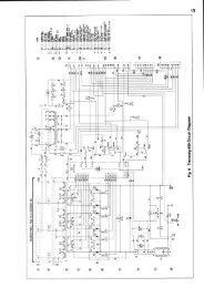
Diagram<br />
<strong>Tradesarc</strong> <strong>200</strong><br />
bh37e<br />
- 18 -
h37e<br />
- 19 -
p<br />
- 20 -
<strong>Tradesarc</strong> <strong>200</strong><br />
Spare parts list<br />
Valid for serial no. 827 -xxx -xxxx<br />
Ordering number<br />
0460 441 881 <strong>Tradesarc</strong> <strong>200</strong>, 230 V 50/60 Hz with MMA--kit<br />
Spare parts are to be ordered through the nearest MUREX agency. Kindly indicate type of unit, serial<br />
number, denominations and ordering numbers according to the spare parts list.<br />
Maintenance and repair work should be performed by an experienced person, and electrical work only<br />
by a trained electrician. Use only recommended spare parts.<br />
bh37m2<br />
- 21 -<br />
Edition 090605
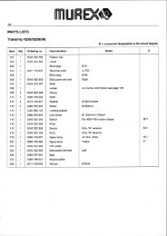
<strong>Tradesarc</strong> <strong>200</strong><br />
C = component designation in the circuit diagram<br />
Item Qty Ordering no. Denomination Notes C<br />
AA1 1 0193 317 001 Switch Included in item AA50 2QF1<br />
AA2 1 - Cord set Included in item AA50<br />
AA3 1 0460 140 001 Rear panel<br />
AA4 1 0460 143 001 Cover<br />
AA5 1 0460 476 881 MMC Module <strong>Tradesarc</strong> <strong>200</strong> Control panel. Including Insulation sticker and<br />
AA6<br />
- 1 0460 420 001 Insulation sticker Included in AA5<br />
AA6 1 0460 600 528 Knob Included in AA5<br />
AA7 1 0193 700 711 Ribbon cable with connectors 34 pole 1XS1, 1XS2<br />
AA8 1 0460 479 004 Side panel right<br />
AA9 1 0460 479 003 Side panel left<br />
AA10 0194 179 327 Screw MRT ground cutter, M5x12<br />
AA11 1 - Front panel Included in item AA51<br />
- 1 0460 690 002 Sticker <strong>Tradesarc</strong> <strong>200</strong><br />
AA14 5 0366 588 001 Nut<br />
AA15 1 0459 280 887 Cable with connector Included in AA51 XS25, XP5<br />
AA16 1 0366 285 001 Protection cap 12 pole, included in AA51<br />
AA17 1 0460 427 001 Bar plus<br />
AA18 1 0460 152 981 Cable set course<br />
AA19 2 0366 247 001 Nut Included in AA51<br />
AA20 2 0366 306 003 Spring washer Ø21/15x1, included in AA51<br />
AA21 2 0160 362 025 Connector OKC 50 Included in item AA51 XS1, XS2<br />
AA22 1 0460 265 001 Strap<br />
AA23 2 0468 497 001 Holder<br />
AA24 6 0469 381 002 Fast lock nut M5<br />
SPARE PARTS SETS<br />
Item Qty Ordering no. Denomination Notes<br />
AA50 1 0460 601 880 Mains module Includes items: AA1 switch, AA2 mains cable with plug, cable clamp and<br />
one ferrite rings 2L2.<br />
AA51 1 0460 379 893 Front complete Includes items: AA11, AA12, AA15, AA16, AA19, AA20, AA21<br />
When replacing “front complete” also item AA5, MMC module, must be<br />
replaced.<br />
bh37maa2<br />
- 22 -<br />
R0460 473 074/E090605/PNO TAG
<strong>Tradesarc</strong> <strong>200</strong><br />
bh37maa2<br />
- 23 -<br />
R0460 473 074/E090605/PNO TAG
<strong>Tradesarc</strong> <strong>200</strong><br />
C = component designation in the circuit diagram<br />
Item Qty Ordering no. Denomination Notes C<br />
AB1 1 0487 631 880 Power supply board <strong>Tradesarc</strong> <strong>200</strong> 2AP1<br />
AB2 1 0193 700 702 Ribbon cable with<br />
connectors<br />
10 pole 20XS3, 20XS4<br />
AB3 1 0487 599 883 Control board Configured for <strong>Tradesarc</strong> <strong>200</strong> 20AP1<br />
AB4 1 0468 940 005 Thermal switch Socket connector 15XS5 included 15ST2<br />
AB5 1 Diode module See item AB50 15D1<br />
AB6 1 0459 177 001 Inductor 15L1<br />
AB7 1 0459 355 881 Transformer Includes: main transformer, socket 15XS4,<br />
socket 15XS6, thermal switch 15ST1<br />
15TM1<br />
AB8 1 0460 117 001 Inductor PFC 15L2<br />
AB9 1 0194 158 003 Capacitor 1000 uF 450 V DC 15C1<br />
AB10 1 0467 065 002 Fan <strong>Tradesarc</strong> <strong>200</strong>, 24V DC; With cables and socket<br />
15xS3<br />
15EV1<br />
AB11 1 Circuit board See item AB51 15AP1<br />
AB12 1 Semiconductor module See item AB51<br />
AB13 1 0468 030 880 Shunt 15RS1<br />
AB14 1 0459 194 001 Busbar<br />
AB15 1 0487 060 880 Secondary board 15AP2<br />
SPARE PARTS SETS<br />
Item<br />
Qty<br />
201i<br />
Ordering no. Denomination Notes<br />
AB50 1 0459 385 881 Diode module kit Includes: item AB5 diode module, screws (type A and B), thermal<br />
compound and roller.<br />
AB51 1 0459 384 884 Power board kit Includes: item AB11 power board, item AB12 semiconductor<br />
module, screws (type A and B), thermal compound and roller.<br />
- 0458 910 002 Roller handle For the roller in the spare parts sets above<br />
- 0192 058 101 Thermal compound<br />
bh37mab2<br />
- 24 -<br />
R0460 473 074/E090605/PNO TAG
<strong>Tradesarc</strong> <strong>200</strong><br />
bh37mab2<br />
- 25 -<br />
R0460 473 074/E090605/PNO TAG
<strong>Tradesarc</strong> <strong>200</strong><br />
Accessories<br />
Strap ................................... 0460 265 001<br />
Cable holder 2pcs ...................... 0460 265 002<br />
Shoulder strap .......................... 0460 265 003<br />
Trolley<br />
for5--10litregasbottle .................... 0459 366 885<br />
Welding cable kit, <strong>Tradesarc</strong> <strong>200</strong> .........<br />
Return cable kit, <strong>Tradesarc</strong> <strong>200</strong> ...........<br />
0700 006 900<br />
0700 006 901<br />
bh37ma<br />
- 26 -<br />
R0460 473 074/E090605/PNO TAG
<strong>Tradesarc</strong> <strong>200</strong><br />
Remote control MMA 1 (10mcable) .......<br />
MMA and TIG: current<br />
0349 501 024<br />
Foot control FS002 ......................<br />
MMA and TIG current<br />
0349 090 886<br />
Remote control unit AT1 .................<br />
MMA and TIG: current<br />
0459 491 896<br />
Remote control unit AT1 CF .............<br />
MMA and TIG: rough and fine setting of<br />
current.<br />
0459 491 897<br />
Remote cable 12 pole - 8 pole<br />
5m.....................................<br />
10m....................................<br />
15m....................................<br />
25m....................................<br />
0459 552 880<br />
0459 552 881<br />
0459 552 882<br />
0459 552 883<br />
bh37ma<br />
- 27 -<br />
R0460 473 074/E090605/PNO TAG
Please ensure that this<br />
Operating Manual is<br />
available to the user of<br />
the equipment.<br />
<strong>Murex</strong> Welding Products Ltd<br />
Hanover House<br />
Queensgate<br />
Britannia Road<br />
Waltham Cross<br />
Hertfordshire EN8 7TF<br />
England