A.Leopard 2-e _A.Comp.07-510-530d - FG Modellsport GmbH
A.Leopard 2-e _A.Comp.07-510-530d - FG Modellsport GmbH
A.Leopard 2-e _A.Comp.07-510-530d - FG Modellsport GmbH

You also want an ePaper? Increase the reach of your titles
YUMPU automatically turns print PDFs into web optimized ePapers that Google loves.
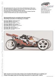
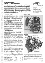
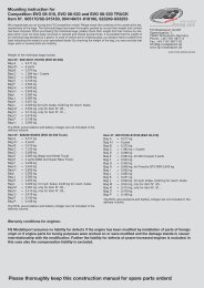
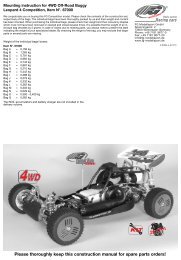
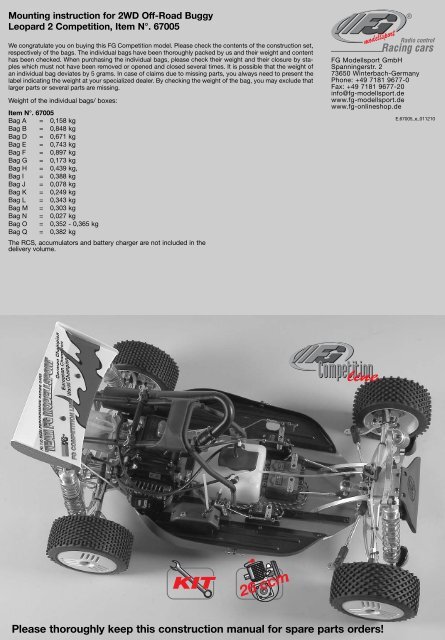
Mounting instruction for 2WD Off-Road Buggy<br />
<strong>Leopard</strong> 2 Competition, Item N°. 67005<br />
We congratulate you on buying this <strong>FG</strong> Competition model. Please check the contents of the construction set,<br />
respectively of the bags. The individual bags have been thoroughly packed by us and their weight and content<br />
has been checked. When purchasing the individual bags, please check their weight and their closure by staples<br />
which must not have been removed or opened and closed several times. It is possible that the weight of<br />
an individual bag deviates by 5 grams. In case of claims due to missing parts, you always need to present the<br />
label indicating the weight at your specialized dealer. By checking the weight of the bag, you may exclude that<br />
larger parts or several parts are missing.<br />
Weight of the individual bags/ boxes:<br />
Item N°. 67005<br />
Bag A = 0,158 kg<br />
Bag B = 0,848 kg<br />
Bag D = 0,671 kg<br />
Bag E = 0,743 kg<br />
Bag F = 0,897 kg<br />
Bag G = 0,173 kg<br />
Bag H = 0,439 kg,<br />
Bag I = 0,388 kg<br />
Bag J = 0,078 kg<br />
Bag K = 0,249 kg<br />
Bag L = 0,343 kg<br />
Bag M = 0,303 kg<br />
Bag N = 0,027 kg<br />
Bag O = 0,352 - 0,365 kg<br />
Bag Q = 0,382 kg<br />
The RCS, accumulators and battery charger are not included in the<br />
delivery volume.<br />
<strong>FG</strong> <strong>Modellsport</strong> <strong>GmbH</strong><br />
Spanningerstr. 2<br />
73650 Winterbach-Germany<br />
Phone: +49 7181 9677-0<br />
Fax: +49 7181 9677-20<br />
info@fg-modellsport.de<br />
www.fg-modellsport.de<br />
www.fg-onlineshop.de<br />
E.67005_e_011210<br />
Please thoroughly keep this construction manual for spare parts orders!
The handling with fuels requires circumspective and careful<br />
handling. Imperatively observe the security advices.<br />
- Refuel only if the engine is switched off!<br />
- Take off the body.<br />
- Thoroughly clean the area around the fuels nipple.<br />
- Remove the fuel filler cap and carefully fill in the fuel mixture.<br />
- Smoking or any kind of open fire is not admitted.<br />
- Fuels might contain solvent-like substances. Avoid contact with skin and<br />
eyes. Wear gloves for refueling. Do not inhale fuel vapors.<br />
- Do not spill any fuel. If you have spilled fuel immediately clean the engine<br />
and the model.<br />
- Make sure that no fuel will get into the soils (environmental protection).<br />
Use an appropriate mat.<br />
- Do not refuel in enclosed rooms. Fuel vapors accumulate at the soil (risk<br />
of explosion).<br />
- Transport and store fuels only in admitted and labeled canisters. Keep<br />
fuel out of the range of children.<br />
- The operator is responsible for any damages caused to third persons in<br />
the operating range of the model, respectively of the engine, if they are<br />
injured or in case of property damage.<br />
- The model must only be passed on to persons who are familiar with this<br />
model and its operation, always provide the operating manual.<br />
- Persons with implanted heart pacemakers must not work on running engines<br />
and on live parts of the ignition system when the engine is being<br />
started.<br />
- The engine must neither be started nor operated in enclosed rooms (without<br />
sufficient ventilation).<br />
- When starting the engine, avoid inhaling the exhausts.<br />
- The model must neither be started nor operated without air filter or without<br />
exhaust system.<br />
- Before every start perform a functional check of the safety-relevant parts.<br />
- The throttle rods must always return automatically to the idle position.<br />
- Any cleaning, maintenance and repair works must only be performed<br />
with the engine being switched off. The engine and silencers are getting<br />
very hot. In particular do not touch the silencer.<br />
Comments regarding the construction manual:<br />
Before starting the assembly please see through this construction manual.<br />
This way you will get an overview of the whole execution.<br />
Please check by means of the parts or bag list if the construction kit is complete<br />
and also check the weight of the individual bags for the positions.<br />
Only this way you may be sure that all parts which you need for the assembly<br />
are available. If a part is missing, please immediately contact your<br />
specialized dealer.<br />
Table of contents<br />
Position 1: CFRP chassis stiffening, ABS splash guards, battery<br />
holder<br />
Position 2: Differential gear<br />
Position 3,4: Aluminium rear axle mounts, rear lower wishbones<br />
Position 5-7: Rear axle<br />
Position 8: Shock absorbers<br />
Position 9: Shock mount, spoiler mount, rear damper protection<br />
Position 10-15: Engine, air filter, gear, fuel tank<br />
Position 16-18: Roll bar, tuning pipe, starter rope<br />
Position 19-24: Servos, receiver box, servo saver<br />
Position 25,26: Front lower wishbones, stabilizer, front axle plate<br />
Position 27-29: Front axle, uprights, front bumper<br />
Position 30,31: Throttle rods<br />
Position 32-35: Hydraulic brake system<br />
Warranty conditions for engines:<br />
<strong>FG</strong> <strong>Modellsport</strong> assumes no liability for defects if the engine has been modified by installation of parts of foreign<br />
origin or if engine parts for tuning purposes were worked on or were modified and the damage stands in causal<br />
interrelationship with the modification. Further the liability for defects of power-increased engines is excluded. In<br />
this case also the compensation liability is excluded.
1. Press M4x12 pan head screws from the bottom<br />
side into the alum. chassis and fix the ABS splash<br />
guards le/ri using disks Ø4,3 and stop nuts M4.<br />
2. Now press the body bolts from the inside into<br />
the ABS splash guards le/ri and fix them with<br />
some superglue, then clip on the body clips.<br />
3. Impress the insert bushes<br />
from the top into the CFRP<br />
chassis stiffening, then mount<br />
it on the aluminium chassis<br />
by using M4x10 countersunk<br />
screws. Caution! Left and<br />
right CFRP chassis stiffenings<br />
differ, pay attention to the<br />
borings.<br />
Aluminium battery<br />
holder brace<br />
Screw<br />
M4x12<br />
Position 1<br />
Parts are in<br />
bag A+L<br />
Stop nut M4<br />
Disk Ø4,3<br />
Aluminium<br />
chassis<br />
Insert bush for<br />
chassis stiffening<br />
Screw<br />
M4x10<br />
CFRP<br />
chassis<br />
stiffening<br />
Screw<br />
4,2x16<br />
Body mount<br />
adjustable<br />
4. Mount the adjustable body mounts on the alum. chassis by using<br />
4,2x16 countersunk screws. Now fix 2,9x9,5 pan head screws into<br />
the second boring from the top of the adjustable body mounts,<br />
impress the o-ring and secure the alum. battery holder brace by<br />
using body clips.<br />
ABS splash<br />
guard<br />
Body bolt<br />
Body clip<br />
O-ring<br />
Ø6x3<br />
Screw<br />
2,9x9,5<br />
Body clip<br />
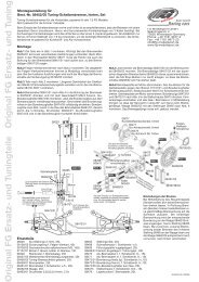
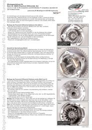
The inserting of the diff. gearwheels or of the<br />
complete package is much easier if you use the<br />
<strong>FG</strong> mounting tool Item N°. 08505.<br />
1. Insert the diff. gearwheels in the alum. diff. housing as described in position 2. The inserting<br />
of the diff. gearwheels is much easier if you use the <strong>FG</strong> mounting tool Item N°. 08505.<br />
2. Lubricate the ball diff. driving axles slightly with grease and press them into the alum. differential<br />
housing.<br />
3. Mount the diff. bevel wheel axle. If the bevel gear axle respectively the driving axles can only<br />
be pushed in severely or if they cannot be pushed in at any position, then you have to dismount<br />
the bevel gearwheels again and repeat the mounting.<br />
4. If the gearwheels have too<br />
much clearance, correct it by<br />
using the enclosed shim rings<br />
5x17x0,1 und 8x20x0,1. Please<br />
make sure that the gearwheel clearance<br />
is not set too narrow.<br />
5. Lubricate the gearwheels slightly<br />
with some multipurpose grease, for<br />
example Item N°. 06501.<br />
6. Now press the parts as shown<br />
in position 2 on the alum. differential<br />
housing in the given sequence:<br />
O-ring large, o-ring small, steel<br />
gearwheel 48 teeth, alum. diff.<br />
bushing. Fix the complete unit by<br />
using M3x8 pan head screws and<br />
disks Ø3,2. Mount the steel<br />
gearwheel 48t. to the alum. diff.<br />
housing using M4x8 countersunk<br />
screws.<br />
Screw<br />
M4x8<br />
Diff. gearwheel<br />
A<br />
O-rings<br />
Diff. bevel<br />
wheel<br />
axle<br />
Diff. gearwheel<br />
B<br />
Shim ring<br />
5x17x0,1<br />
Alum.<br />
differential<br />
housing<br />
Ball diff.<br />
driving axle<br />
Shim ring<br />
8x20x0,1<br />
Steel gearwheel<br />
48 teeth<br />
Alum. diff.<br />
bushing<br />
All metric screws need to be secured with thread lock fluid.<br />
Position 2<br />
Parts are in<br />
bag B<br />
Disk Ø3,2<br />
Screw<br />
M3x8
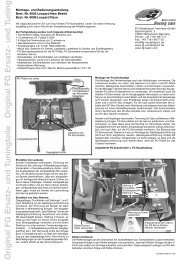
Position 3<br />
Parts are in<br />
bag B<br />
1. Press the aluminium rear axle<br />
mounts left/right on the ball bearings<br />
of the differential gear as<br />
shown in position 3.<br />
2. Place the alum. rear axle mounts<br />
left/right on the alum. chassis and<br />
fix them using M5x14 countersunk<br />
screws.<br />
3. Mount the alum. connecting<br />
brace to the right alum. rear axle<br />
mount using M4x20 pan head<br />
screw and disk Ø4,3.<br />
4. Impress the guide bushes with<br />
collar into the alum. wishbone<br />
fixings 2° left/right and mount them<br />
with alum. adjusting key 2° and<br />
M5x14 countersunk screws to the<br />
rear axle mounts left/right.<br />
Alum.<br />
connection<br />
brace<br />
Alum. chassis<br />
Screw<br />
M4x20<br />
Disk Ø4,3<br />
Impress<br />
guide bushes<br />
Alum. wishbone<br />
fixing<br />
2°, left<br />
Alum. rear<br />
axle mount<br />
right<br />
Screw<br />
M5x14<br />
Alum. rear<br />
axle mount<br />
left<br />
Screw<br />
M5x14<br />
Alum. adjusting<br />
key 2°<br />
Guide bush<br />
with collar<br />
Position 4<br />
Parts are in<br />
bag B<br />
1. Impress the guide<br />
bushes with collar<br />
into the rear lower<br />
alum. wishbones from<br />
inside and outside.<br />
2. Screw the headless pin<br />
M5x20 from the top centrally<br />
into the rear lower alum. wishbones<br />
using screw retention.<br />
3. Fix the rear lower alum. wishbones with<br />
wishbone pins 6x85mm to the alum. wishbone<br />
fixings 2° left/right, groove and thread must<br />
face backwards.<br />
Make sure the mounted wishbones can be moved easily up and down.<br />
4. Screw the 7mm ball joints on the M4x14 headless pins until they are in contact and<br />
until they are 90° twisted. Impress a steel ball 7mm and steel ball Ø7x5mm each one<br />
side of the ball joints 7mm.<br />
5. Press the ball joints 7mm with the side of the steel ball Ø7x5mm on each side of the<br />
5mm stabilizer and fix them using the 5mm alum. retaining collar (collar facing the ball<br />
joint) and the headless pin M4x4.<br />
6. Mount the ball joints 7mm with the side of the steel ball 7mm to the rear lower alum.<br />
wishbones (with the collar of the steel ball facing backwards) using M3x20 pan head<br />
screws. Impress the 5mm stabilizer into the alum. rear axle mounts.<br />
Headless<br />
pin M5x20<br />
Rear lower<br />
alum. wishbone<br />
Wishbone pin 6x85<br />
Ball<br />
joint<br />
7mm<br />
Stabilizer<br />
5mm<br />
Headless<br />
pin M4x4<br />
Steel<br />
ball<br />
Ø7 x<br />
5mm Alum. retaining<br />
collar<br />
5mm<br />
Headless pin M4x14<br />
Steel<br />
ball<br />
7mm<br />
Screw<br />
M3x20<br />
Hint: To withdraw the rear lower wishbone pins 6x85mm screw an M4 screw into the tap<br />
hole of the wishbone pins 6x85mm and pull them out.<br />
Position 5<br />
Parts are<br />
in bag D<br />
Ball<br />
driving axle<br />
Protection bellow<br />
Slightly lubricate the<br />
ball driving shaft<br />
Distance<br />
disks<br />
Balls for<br />
driving shaft<br />
Ball diff. axle<br />
Apply lubricating<br />
grease<br />
Impress<br />
guide bushes<br />
Guide bush<br />
with collar<br />
Mounting of the ball driving shafts<br />
Stick the distance disks into the round recess of the ball<br />
driving axles as well as in the ball diff. axle using some<br />
multipurpose grease. Mount the protection bellows to the<br />
ball driving shafts according to the illustration. Slightly grease<br />
the ball area when mounting the protection bellow.<br />
Apply some lubricating grease on the ball holes of the driving<br />
shafts and impress the balls. The balls will be held by<br />
the lubricating grease and this way the driving shaft can be<br />
mounted more easily. Now push the complete ball driving<br />
shaft into the differential axle and driving axle. Push the<br />
protection bellows over the ball diff. axles and driving<br />
axles.
Position 6<br />
Parts are<br />
in bag D<br />
Ball diff.<br />
driving axle<br />
1. Press the ball driving axles of the premounted ball driving set (position<br />
5) into the alum. uprights equipped with ball bearings and fix the<br />
alum. square wheel driver 9,5mm/M6 (shoulder facing the ball bearing)<br />
on the areas of the ball driving axles (use high-strength screw retention).<br />
2. Push the alum. uprights and wishbone pins 6x65mm into the rear<br />
lower alum. wishbones as shown in position 6.<br />
3. Press each one adjusting clip front and rear between the alum.<br />
uprights and rear lower alum. wishbones on the wishbone pins, secure<br />
the alum. uprights with M3x3 headless pins. Check the alum. uprights<br />
on free movement.<br />
4. Screw the ball joints 10mm M7 on the adjusting screws ri/le<br />
M7x102mm, impress alum. joint ball Ø10x13 and alum. ball retaining<br />
collar Ø10x15 each one side of the ball joint 10mm M7, then screw the<br />
2,9x13 pan head screws into the ball joints 10mm M7 and adjust the<br />
ball clearance (position 7).<br />
5. Mount the wishbone pins 6x63mm (with the side of the alum. ball<br />
retaining collar Ø10x15, collar in driving direction) through the premounted<br />
upper wishbones, now mount the alum. rear axle mounts ri/le<br />
into the lower inside boring and secure them using Ø5 securing disks<br />
and M4x4 headless pin.<br />
6. Fix the premounted upper wishbones through the alum. joint ball<br />
Ø10x13 (collar facing the alum. upright) using M5x25 pan head screws<br />
to the alum. uprights le/ri.<br />
Securing<br />
disk Ø5<br />
Wishbone<br />
pin 6x65<br />
Adjusting<br />
clips<br />
Alum. upright<br />
left<br />
Alum. square<br />
wheel driver<br />
9,5mm/M6<br />
Wheel nut<br />
Rear lower<br />
alum. wishbone<br />
Headless<br />
pin M3x3<br />
Headless<br />
pin M6x6<br />
Ball driving<br />
axle<br />
Distance<br />
disk<br />
Balls for<br />
driving<br />
shaft<br />
Ball<br />
driving<br />
shaft<br />
Protection bellow<br />
Alum.<br />
joint<br />
ball<br />
Ø10x13<br />
Securing<br />
disk Ø5<br />
Alum. ball<br />
retaining<br />
collar<br />
Ø10 x 15<br />
Headless<br />
pin M4x4<br />
Wishbone pin 6x63<br />
Adjusting screw<br />
ri/le M7 x 102<br />
Ball joint<br />
10mm M7<br />
Screw<br />
2,9x13<br />
Screw<br />
M5x25<br />
Position 7<br />
Parts are<br />
in bag D<br />
Adjust rear upper wishbones<br />
to approx. 65 mm<br />
Use high-strength<br />
screw retention<br />
Adjusting clips<br />
All metric screws need to be secured<br />
with thread lock fluid.
Position 8<br />
Parts are<br />
in bag E<br />
Threaded<br />
piston rod,<br />
short + long<br />
Pliers Item N°.<br />
06854<br />
Upper alum.<br />
shock absorber<br />
seal<br />
Plastic<br />
adjusting<br />
ring<br />
Plastic bush<br />
Ø5/Ø7x6,5<br />
O-ring<br />
Ø22x1,5<br />
Position 8a<br />
Parts are<br />
in bag E<br />
Plastic guiding<br />
disk<br />
Volume<br />
control<br />
Ø20<br />
Gasket Ø4,5<br />
Position 8b<br />
Parts are<br />
in bag E<br />
Threaded<br />
piston rod,<br />
short + long<br />
Stop nut<br />
M3<br />
Disk<br />
Ø3,2<br />
Plastic damper<br />
piston<br />
Lower alum.<br />
shock absorber<br />
seal, premounted<br />
Lower alum.<br />
shock absorber<br />
seal<br />
O-ring<br />
Ø24x1,5<br />
Plastic<br />
bush<br />
Ø4,5/Ø7x4<br />
Lower shock<br />
fastening,<br />
reinforced<br />
O-ring<br />
Ø20x1,5<br />
Lower alum.<br />
shock absorber<br />
seal<br />
1. Press plastic bush Ø5/Ø7x6,5 into the upper alum. shock absorber seals as shown in position 8 and insert the o-ring Ø22x1,5 in the groove.<br />
2. Insert o-ring Ø24x1,5 in the groove of the plastic adjusting rings.<br />
3. Mount the o-ring Ø20x1,5 into the groove of the lower alum. shock absorber seals.<br />
4. Screw the lower reinforced shock fastenings on the thread of the threaded piston rods short and long until the thread can not be seen anymore.<br />
Make sure you do not damage the piston rod. Therefore we recommend to use the pliers Item N°. 06854.<br />
5. Impress the plastic bushes Ø4,5/Ø7x4 and gaskets Ø4,5 into the lower alum. shock absorber seals, then press the volume control Ø20 on the<br />
plastic guiding disks and impress into the lower alum. shock absorber seals.<br />
6. Push the threaded piston rods short and long carefully and with some shock absorber oil through the premounted alum. shock absorber seals<br />
as shown in position 8b, then mount the plastic damper piston with disk Ø3,2 and stop nut M3. Do not tighten the stop nuts M3 too firm, make<br />
sure the plastic damper pistons can still be moved.<br />
Upper alum.<br />
shock absorber<br />
seal<br />
Position 8c<br />
Parts are<br />
in bag E<br />
Plastic adjusting<br />
ring<br />
Alum. shock<br />
absorber<br />
housing<br />
short + long<br />
Lower alum.<br />
shock absorber<br />
seal, premounted,<br />
short + long<br />
Shock absorber<br />
oil 1000<br />
7. Screw the plastic adjusting<br />
rings with some oil on the alum.<br />
shock absorber housing short<br />
and long as shown in position 8c.<br />
8. Fix the assembled alum. shock<br />
absorber seals with short piston<br />
rod into the short shock absorber<br />
housing.<br />
Fix the assembled alum. shock<br />
absorber seals with long piston<br />
rod into the long shock absorber<br />
housing.<br />
9. Fill the shock absorbers with<br />
shock absorber oil up to the top<br />
and move the piston rod carefully<br />
several times in and out so that<br />
the air bubbles in the oil come<br />
upwards. As soon as no air bubbles<br />
appear anymore, pull the<br />
piston rod completely out and<br />
lock the shock absorbers with the<br />
upper alum. shock absorber<br />
seals.<br />
10. Mount the orange damper<br />
pressure spring 2,4x40, the plastic<br />
spring guide and red damper<br />
pressure spring 2,4x10⁵ on the<br />
long rear shock absorbers and<br />
secure them with the alum. spring<br />
plates as shown in position 8d.<br />
Fix the orange damper pressure<br />
spring 2,4x10⁵ on the short front<br />
shock absorbers and secure it<br />
using the alum. spring plates.<br />
Shock absorber<br />
long, mounted<br />
Damper<br />
pressure<br />
spring<br />
orange<br />
2,4x40<br />
Plastic<br />
adjusting<br />
ring<br />
Plastic spring<br />
guide<br />
Damper<br />
pressure<br />
spring red<br />
2,4x10⁵<br />
Damper pressure<br />
spring<br />
orange<br />
2,4x10⁵<br />
Position 8d<br />
Parts are<br />
in bag E<br />
Shock absorber<br />
short, mounted<br />
Alum. spring<br />
plate
1. Fix the rear alum. damper plate<br />
to the le/ri alum. rear axle mounts<br />
using M4x18 pan head screws and<br />
disks Ø4,3 ( Mount the cut-out of<br />
the alum. shock mount in driving<br />
direction).<br />
2. Mount the rear assembled lower<br />
shock absorbers to the rear lower<br />
alum. wishbones (medium threaded<br />
hole) using M4x20 pan head<br />
screws. Screw M5x25 pan head<br />
screws in the outer threaded holes<br />
of the alum. damper plate rear, then<br />
fix the shock absorbers at the top<br />
using disks Ø5,3 and stop nuts M5.<br />
3. Mount the rear CFRP damper<br />
protection to the le/ri alum. rear<br />
axle mount using M4x18 pan head<br />
screws and disks Ø4,3 on both<br />
sides of the rear CFRP damper protection.<br />
4. Fix the spoiler mount at the rear<br />
alum. damper plate using M4x14<br />
cylinder head screws, mount the<br />
plastic brace Ø10x80mm and the<br />
adjusting parts spoiler mount in<br />
between using 4,2x32 pan head<br />
screws as shown in position 9. Clip<br />
the body clips on the adjusting<br />
parts spoiler mount.<br />
5. Assemble the mount for the pull<br />
start to the rear alum. damper plate<br />
using M5x10 pan head screws as<br />
shown in position 9.<br />
Screw<br />
M5x25<br />
Screw<br />
M4x14<br />
Rear shock<br />
absorber<br />
mounted<br />
Screw<br />
M4x20<br />
Disk Ø5,3<br />
Stop nut<br />
M5<br />
Rear CFRP<br />
damper protection<br />
Body clip<br />
Screw<br />
M4x18<br />
Disk Ø4,3<br />
Spoiler<br />
mount<br />
Plastic brace<br />
Ø10x80<br />
Rear<br />
alum.<br />
damper<br />
plate<br />
Adjusting part<br />
spoiler mount<br />
Position 9<br />
Parts are<br />
in bag B,E+M<br />
Screw<br />
M5x10<br />
Screw<br />
4,2x32<br />
Mount for<br />
pull start<br />
Engine<br />
Position 10<br />
Parts are<br />
in bag H<br />
1. Mount the small alum. engine mount to the engine using<br />
M5x40 pan head screws and counter with M5 stop nuts.<br />
For this purpose the original screws of the engine have to<br />
be removed.<br />
2. Apply screw retention lacquer on the four headless pins<br />
M5x20 and screw them into the engine housing until they<br />
poke out of the housing approx. 9mm.<br />
3. Press the engine flange for the engine quick fastening<br />
(with the cutout facing the cylinder) on the housing or<br />
respectively the headless pins and fix it using M5 stop nuts.<br />
4. Fix the carrier for the clutch shoes to the engine using an<br />
M6x14 hexagon screw with pressed on disk.<br />
Engine flange<br />
for engine<br />
quick<br />
fastening<br />
Carrier for<br />
clutch shoes<br />
Alum. engine<br />
mount<br />
small<br />
Stop<br />
nut M5<br />
Hint: If the <strong>FG</strong> piston stop pin Item N°. 08542 is used, the<br />
assembling of the clutch shoe carrier will be considerably<br />
simplified.<br />
Screw for carrier<br />
M6x14 with disk<br />
Stop<br />
nut M5<br />
Headless<br />
pin M5x20<br />
Screw<br />
M5x40<br />
All metric screws need to be secured with thread lock fluid.
1. Clip the clutch spring in<br />
the clutch shoes and push<br />
the clutch shoes together<br />
as pictured.<br />
2. Place the shaft washers<br />
on the set screws for the<br />
clutch shoes and push<br />
them from the side with the<br />
arrows (running direction of<br />
the engine) into the clutch<br />
shoes, then fix it on the<br />
clutch shoe carrier using<br />
6x15x1 disks.<br />
Hint: If the <strong>FG</strong> piston stop<br />
pin Item N°. 08542 is used,<br />
the assembling of the<br />
clutch will be considerably<br />
simplified.<br />
Screw<br />
M5x16<br />
Manifold<br />
Engine<br />
Silencer gasket<br />
Disk<br />
6x15x1<br />
Driving direction<br />
Air filter<br />
adapter<br />
Clutch<br />
shoes<br />
Clutch<br />
spring<br />
Basic<br />
body<br />
O-ring for air<br />
filter adapter<br />
Screw<br />
4,2x13<br />
Screw<br />
4,2x13<br />
Foam filter<br />
Position 11<br />
Parts are<br />
in bag H,J<br />
Filter cover<br />
Screw<br />
4,2x16<br />
Shaft washer<br />
Set screw for<br />
clutch shoes<br />
3. Mount the manifold to the engine using M5x16 pan head screws and silencer gasket.<br />
4. Insert o-ring for air filter adapter in the basic body and fix it to the air filter adapter using 4,2x13 countersunk screws.<br />
5. Press the oiled foam filter on the basic body and fix it with the filter cover and a 4,2x16 countersunk screw.<br />
Hint: The enclosed foam filter is ready-to-use and oiled. If at a later point of time a filter is required which is ready-to-use, please proceed as follows:<br />
in order to oil the foam filter place the filter together with some <strong>FG</strong> filter oil for foam filter Item N°. 06441 in a plastic bag and press together<br />
to rub it in.<br />
Position 12<br />
Parts are<br />
in bag I<br />
Engine flange for<br />
engine quick<br />
fastening<br />
Screw<br />
M5x14<br />
Alum.<br />
gear flange<br />
engine mount<br />
Tuning<br />
clutch bell<br />
Set screw<br />
10x16x1<br />
Pre-filter for<br />
intake air<br />
filter<br />
Screw<br />
M4x14<br />
Screw<br />
M6x16<br />
Set screw<br />
10x16x1<br />
Steel<br />
gearwheel<br />
18 teeth<br />
Steel gearwheel<br />
14 teeth<br />
Alum.<br />
gear<br />
plate<br />
Screw<br />
M4x14<br />
Screw<br />
M6x10<br />
Headless<br />
pin M5x5<br />
Tuning gear<br />
shaft<br />
Steel<br />
gearwheel<br />
46 teeth<br />
Headless<br />
pin M5x5<br />
longer<br />
shaft flats<br />
Alum.<br />
gearwheel<br />
adapter<br />
All metric screws need to be secured with thread lock fluid.<br />
Screw<br />
M5x10<br />
Headless pin<br />
M6x6<br />
Screw<br />
M6x10<br />
1. Pull the pre-filter for the intake air filter<br />
over the completely mounted air filter,<br />
pull it together with the lace and fix<br />
it with a tie.<br />
2. Impress the tuning clutch bell with<br />
two set screws 10x16x1 in the alum.<br />
gear plate as shown in position 12,<br />
now mount set screw 10x16x1 and<br />
steel gearwheel 18 teeth on the flats of<br />
the tuning clutch bell using M5x5<br />
headless pins, secure with M6x10 pan<br />
head screw.<br />
3. Assemble the alum. gear plate at the<br />
alum. gear flange-engine mount using<br />
M4x14 cylinder head screws. Screw<br />
M5x14 pan head screw into the alum.<br />
gear flange-engine mount, but do not<br />
tighten yet.<br />
4. Press the tuning gear shaft at the<br />
side with the longer shaft flats flush<br />
into the alum. gearwheel adapter and<br />
secure with M6x6 headless pins and<br />
M6x10 pan head screws.<br />
5. Mount steel gearwheel 46 teeth to<br />
the alum. gearwheel adapter using<br />
M5x10 pan head screws.<br />
6. Press the tuning gear shaft through<br />
the ball bearings of the alum. gear<br />
plate and alum. gear flange-engine<br />
mount.<br />
7. Press the steel gearwheel 14 teeth<br />
on the tuning gear shaft as shown in<br />
position 12 and fix it using M5x5 headless<br />
pins on the flats of the tuning gear<br />
shaft, secure with M6x16 countersunk<br />
screw. Use high-strength screw retention.<br />
8. Plug the complete gear unit on the<br />
engine flange for engine quick fastening.
1. Insert the premounted engine<br />
in the alum. chassis as illustrated<br />
in position 13 and fix it<br />
using an M4x25 pan head<br />
screw and disk Ø4,3 through<br />
the left alum. rear axle mount,<br />
also fix it with the alum. connecting<br />
brace at the alum. gear<br />
flange-engine mount. Just apply<br />
the M4x25 pan head screw, do<br />
not tighten yet (see also position<br />
14).<br />
2. Mount the pre-assembled<br />
engine in the alum. chassis<br />
using M4x14 countersunk<br />
screws and engine fixing disks.<br />
3. Fix the tank in the alum.<br />
chassis using M4x8 countersunk<br />
screws as shown in position<br />
13.<br />
Position 13<br />
Parts are<br />
in bag H+K<br />
Tank complete<br />
Screw<br />
M4x25<br />
Disk<br />
Ø4,3<br />
Alum. chassis<br />
Engine fixing<br />
disk<br />
Screw<br />
M4x14<br />
Screw<br />
M4x8<br />
Screw<br />
M4x8<br />
Please pay attention that drive gearwheels, drive shafts a.s.o. can be moved easily and without any resistance.<br />
Position 14<br />
Parts are<br />
in bag I<br />
Screw<br />
M5x14<br />
Screw<br />
M4x25<br />
Disk Ø4,3<br />
Alum. gear flangeengine<br />
mount<br />
Alum. connecting<br />
brace<br />
Alum. rear<br />
axle mount<br />
left<br />
1. Tighten the M4x25 pan head screw after<br />
tightening the engine fixing screws.<br />
2. Tighten the M5x14 pan head screw at the<br />
alum. gear flange-engine mount.
Install fuel hoses as illustrated and<br />
shorten if necessary.<br />
Venting hose<br />
Position 15<br />
Parts are<br />
in bag K<br />
Return<br />
hose<br />
Intake hose<br />
1. Screw M4x20 headless pins centric into<br />
the short roll bar and screw the alum.<br />
distances Ø10x70mm on top, then mount<br />
the complete roll bar through the CFRP<br />
chassis stiffening to the alum. chassis using<br />
M4x25 countersunk screws.<br />
2. Screw M5x30 headless pins centric into<br />
the plastic braces Ø10x60 as shown in position<br />
16, then screw on the long plastic braces.<br />
3. Fix the body mounts from the bottom at<br />
the long plastic braces into the front boring<br />
using 4,2x22 countersunk screws and press<br />
the body clips on. Mount the long preassembled<br />
plastic braces to the rear alum.<br />
damper plate and to the short front roll bar<br />
using 4,2x22 and 4,2x32 pan head screws<br />
as shown in position 16.<br />
4. Fix the short plastic brace to the long plastic<br />
brace using 4,2x22 pan head screws as<br />
illustrated in position 16.<br />
5. Assemble the plug protection at the long<br />
plastic braces using 4,2x13 countersunk<br />
screws.<br />
Roll bar<br />
short<br />
Plastic<br />
brace short<br />
Plug protection<br />
Alum. chassis<br />
Alum.<br />
distance<br />
Ø10x70<br />
Screw<br />
M4x25<br />
Screw<br />
4,2x32<br />
Screw<br />
4,2x22<br />
Plastic<br />
brace long<br />
Body<br />
mount<br />
Headless<br />
pin M5x30<br />
Screw<br />
4,2x22<br />
Body clip<br />
Position 16<br />
Parts are<br />
in bag M<br />
Alum.<br />
damper<br />
plate rear<br />
Screw<br />
4,2x22<br />
Plastic brace<br />
Ø10x60<br />
Headless pin<br />
M4x20<br />
Screw<br />
4,2x13<br />
All metric screws need to be secured with thread lock fluid.
Tension spring<br />
Screw<br />
M4x18<br />
Plastic<br />
brace long<br />
Fabric hose Ø24 x 23<br />
Fixing wire for silencer<br />
<strong>FG</strong> Steel-Power Tuning pipe<br />
Headless<br />
pin M5x5<br />
Fixing wire for silencer<br />
Headless<br />
pin M5x5<br />
Stop nut M4<br />
Disk Ø4,3<br />
Screw<br />
M4x18<br />
Alum. damper<br />
plate rear<br />
Position 17<br />
Parts are<br />
in bag O<br />
1. Press the <strong>FG</strong> Steel-Power Tuning pipe with fabric hose on the manifold as shown<br />
in position 17 and secure with the tension springs. Dampen the fabric hose before<br />
with some oil or grease.<br />
2. Bend the fixing wires for the <strong>FG</strong> Steel-Power Tuning pipe as illustrated in position<br />
17 and fix them at the long plastic brace and the rear alum. damper plate using<br />
M4x18 pan head screws, disks Ø4,3 and stop nuts M4. Clamp the fixing wires with<br />
the M5x5 headless pins. Align the silencer via both fixing wires in a way that it does<br />
not touch at any position.<br />
Position 18<br />
Parts are<br />
in bag B<br />
Clip the rope starter<br />
in the holder
Throttle/brake<br />
servo<br />
Steering servo<br />
Plastic servo<br />
mount small<br />
Before you start mounting the<br />
remote control components,<br />
please also thoroughly read<br />
the enclosed RC manual and<br />
deal with transmitter, receiver<br />
and servos. Charge the receiver<br />
and transmitter batteries<br />
and check the parts on their<br />
function.<br />
Screw<br />
M3x16<br />
Disk Ø3,2<br />
ABS splash<br />
guard<br />
Distance bolts<br />
Ø8x28<br />
Brake<br />
servo<br />
Plastic servo<br />
mount small<br />
Alum. servo<br />
mount<br />
Position 19<br />
Parts are<br />
in bag L<br />
Screw<br />
4,2x13<br />
Disk<br />
Ø4,3<br />
Screw<br />
4,2x16<br />
Screw<br />
4,2x13<br />
Screw<br />
M4x10<br />
Screw<br />
4,2x16<br />
Screw<br />
M4x10<br />
Alum. chassis<br />
1. Mount distance bolts Ø8x28mm to the right ABS splash guard using 4,2x13 pan head screws and disks Ø4,3 as shown in position 19.<br />
2. Fix the small plastic servo mount to the alum. chassis using 4,2x16 countersunk screws. Mount the throttle/brake servo and brake servo into<br />
the small plastic servo mounts using the enclosed fixing rubber bushings and screws as shown in position 19.<br />
3. Fix the alum. servo mount to the alum. chassis using M4x10 countersunk screws. Mount the steering servos into the alum. servo mounts using<br />
the enclosed fixing rubber bushings, M3x16 pan head screws and disks Ø3,2 as shown in position 19.<br />
4. Assemble the receiver battery to the alum. battery brace using insulating tape as illustrated in position 20.<br />
5. Fix the aerial mount at the top part of the receiver box using a 2,9x19 pan head screw. Press the aerial tubing into the aerial mount and clamp<br />
it using a 2,9x9,5 pan head screw.<br />
6. Press the bottom part of the receiver box on the distance bolts Ø8x28mm. Connect the servo cable, battery cable a.s.o. to the receiver and<br />
check on function.<br />
7. To lead the cables through you have to drill a hole of approx. Ø8mm at a suitable place of the receiver box top.<br />
8. Store receiver and the rest of the cables in the receiver box, push thew aerial cable of the receiver into the aerial tubing.<br />
9. Place an o-ring between the receiver box bottom and receiver box top for sealing.<br />
10. Screw the receiver box on the distance bolts Ø8x28mm using 4,2x16 pan head screws.<br />
Hint: Cover the bottom part of the receiver box with some foam in order to protect the receiver against vibrations.<br />
Aerial tubing<br />
Alum. battery<br />
holding brace<br />
Due to the constricted space<br />
conditions we recommend to<br />
use the <strong>FG</strong> Mini Racing pack<br />
06543/01 for the receiver/servo<br />
power supply. Additionally the<br />
<strong>FG</strong> receiver cable Item N°.<br />
06547/02 or <strong>FG</strong> receiver cable<br />
with switch <strong>FG</strong>/JR Item N°.<br />
06551 is required.<br />
Screw<br />
2,9x19<br />
Screw<br />
2,9x9,5<br />
receiver box<br />
Aerial<br />
mount<br />
Screw<br />
4,2x16<br />
Position 20<br />
Parts are<br />
in bag L<br />
All metric screws need to be secured with thread lock fluid.
Position 21<br />
Parts are<br />
in bag L<br />
Screw<br />
M5x16<br />
Tension sleeve for<br />
servo saver<br />
1. Impress the tension sleeve for servo saver from the top through alum. servo saver part B and<br />
servo saver part A.<br />
2. Mount the servo saver spring with nut M10 for servo saver on the thread of the tension<br />
sleeve for servo saver as shown in position 21 and check servo saver on smooth running.<br />
3. Lubricate the servo saver axle slightly and press it from the bottom into the tension sleeve<br />
as shown in position 21. Secure the servo saver axle with an M5x16 pan head screw. Use<br />
screw retention lacquer.<br />
Alum. Servo<br />
saver, Part B<br />
Servo<br />
saver<br />
spring<br />
Servo<br />
saver<br />
Part A<br />
Nut M10 for<br />
Servo saver<br />
Servo saver<br />
axle<br />
Alum. joint<br />
ball<br />
Adjusting screw<br />
ri./le. M7x102<br />
Alum.<br />
joint<br />
ball<br />
Screw<br />
M4x16<br />
Adjust track rod to<br />
approx. 66 mm<br />
Screw<br />
2,9x13<br />
Ball joint<br />
10mm M7<br />
Ball joint<br />
10mm M7<br />
Screw<br />
2,9x13<br />
Stop<br />
nut M4<br />
Screw<br />
M3x25<br />
Servo saver<br />
mounted<br />
Track rod<br />
mounted<br />
1. Screw the ball joints 10mm M7 on the adjusting screws<br />
ri/le M7x102mm as shown in position 22 and impress the<br />
alum. joint balls in the ball joints 10mm M7, screw 2,9x13<br />
pan head screws into the ball joints 10mm M7 and adjust<br />
the ball clearance. Fix the mounted track rods to the preassembled<br />
servo saver (collar of the alum. joint ball must<br />
face the mounted servo saver, see illustration) using M4x16<br />
cylinder head screws and stop nuts M4.<br />
2. Screw ball joints 7mm on the track rods ri/le<br />
M4x85mm and impress each one steel ball 7mm and<br />
steel ball Ø7x6,5 into the ball joints.<br />
3. Screw M3x25 pan head screws from the bottom into<br />
the inner borings of the mounted servo saver as shown<br />
in position 22. Fix the steering rods to the mounted<br />
servo saver (the collar of the steel ball 7mm must face<br />
the servo saver) using disks Ø3,2 and stop nuts M3 on<br />
the M3x25 pan head screws.<br />
Ball joint<br />
7mm<br />
Steering rods<br />
ri./le., M4x85<br />
Ball joint<br />
7mm<br />
Stop<br />
nut M3<br />
Steel ball<br />
7mm<br />
Disk Ø3,2<br />
Steel ball<br />
Ø7x6,5<br />
Steering rods<br />
mounted<br />
Position 22<br />
Parts are<br />
in bag L
Position 23<br />
Parts are<br />
in bag L<br />
Servo saver<br />
mounted<br />
Alum distance<br />
for servo<br />
saver<br />
Alum. chassis<br />
1. Mount the pre-assembled servo saver<br />
on the alum. chassis using M5x25 countersunk<br />
screw and alum. distance as<br />
shown in position 23.<br />
Screw<br />
M5x25<br />
2. Switch on the remote control system, set the trimming of<br />
the steering to central position.<br />
3. First mount an assembled steering rod (collar of the ball<br />
must face towards the servo arm) to the servo arm using<br />
M3x18 pan head screw, disk Ø3,2 and stop nut M3 as<br />
shown in position 24. Press the servo arm on the toothing of<br />
the steering servo as illustrated in position 24 and fix it with<br />
enclosed screw. The servo arm should be mounted in 90°<br />
position to the steering servo, it may be necessary to shorten<br />
it depending on the version. Now fix the second assembled<br />
steering rod to the second servo arm in the same way,<br />
both steering rods must have the identical length, make<br />
sure you are able to press the servo arm easily and without<br />
any resistance on the toothing of the steering servo.<br />
Position 24<br />
Parts are<br />
in bag L<br />
Servo arm<br />
Stop<br />
nut<br />
M3<br />
Steering rods<br />
mounted<br />
Screw<br />
M3x18<br />
Disk Ø3,2<br />
All metric screws need to be secured with thread lock fluid.
Alum. front<br />
axle mount A<br />
Alum.<br />
spring<br />
deflection<br />
stop<br />
Screw<br />
M4x8<br />
Securing<br />
disk Ø5<br />
Guide bush<br />
with collar<br />
Position 25<br />
Parts are<br />
in bag F<br />
Screw<br />
M4x14<br />
Alum. front<br />
axle mount B<br />
Screw<br />
M4x14<br />
Wishbone pin 6x88<br />
Alum. front<br />
axle mount C<br />
Adjusting clips<br />
Headless<br />
pin M5x10<br />
Alum. chassis<br />
Screw<br />
M4x10<br />
Alum. front<br />
axle support<br />
Screw<br />
M4x14<br />
1. Place the alum. front axle<br />
mounts A, B and C on the alum.<br />
chassis and fasten them using<br />
M4x14 countersunk screws as<br />
pictured in position 25.<br />
2. Mount the alum. spring<br />
deflection stops to the alum.<br />
front axle mount A using M4x8<br />
pan head screws as shown in<br />
position 25.<br />
3. Mount the alum. front axle<br />
support to the alum. front axle<br />
mount B using M4x10 pan head<br />
screws and to the alum. chassis<br />
using M4x14 countersunk<br />
screws as illustrated in position<br />
25.<br />
4. Secure the impressed ball<br />
bushes in the front lower alum.<br />
wishbones with M3x6 pan head<br />
screws.<br />
5. Press the guide bushes with<br />
collar into the front lower alum.<br />
wishbones.<br />
6. Screw the M5x20 headless<br />
pins centric from below and the<br />
M5x10 headless pins centric<br />
from the top into the front lower<br />
alum. wishbones as shown in<br />
position 25 (use screw retention).<br />
Headless<br />
pin M5x20<br />
Front lower<br />
alum. wishbone<br />
Screw<br />
M3x6<br />
Ball<br />
bush<br />
7. Place the front lower alum. wishbones between the alum. front axle<br />
mounts A + C as shown in position 25. Impress the wishbone pins<br />
6x88mm in the alum. front axle mounts A + C (threaded hole must face<br />
forwards) and through the pre-assembled front lower alum. wishbones,<br />
secure with Ø5 securing disks. Press each two adjusting clips on the<br />
wishbone pins 6x88mm between front lower alum. wishbone and alum.<br />
front axle mount C. Make sure the wishbones can be moved easily up<br />
and down.<br />
Hint: To remove the front lower wishbone pins 6x88mm screw an M4<br />
screw into the threaded hole of the wishbone pin 6x88mm and pull it out.<br />
1. Mount the front alum. damper<br />
plate to the reinforcing plate for the<br />
front axle using M5x14 pan head<br />
screws as shwon in position 26.<br />
2. Fix the support for body mount<br />
to the adjustable body mount<br />
54mm as pictured in position 26<br />
and fasten it at the reinforcing plate<br />
for front axle using an 4,2x16 countersunk<br />
screw.<br />
3. Fasten the assembled reinforcing<br />
plate on the alum. front axle<br />
mounts A + B using M4x10 pan<br />
head screws.<br />
4. Screw ball joints 7mm on the<br />
M4x14 headless pins until they are<br />
in contact and 90° distorted.<br />
Impress each one steel ball 7mm<br />
and steel ball Ø7x5mm, Ø4 in one<br />
side of the ball joints 7mm.<br />
5. Press the ball joint 7mm (steel<br />
ball side Ø7x5mm, Ø4) on each one<br />
end of the front stabilizer 4mm and<br />
fasten with collet 4mm and headless<br />
pin M3x3.<br />
Position 26<br />
Parts are<br />
in bag G<br />
Reinforcing<br />
plate for<br />
front axle<br />
Screw<br />
M4x10<br />
Alum. damper<br />
plate<br />
front<br />
Screw<br />
M5x14<br />
Body mount adjustable<br />
54mm,<br />
support for body<br />
mount,<br />
body clip<br />
Screw<br />
4,2x16<br />
Screw<br />
M4x10<br />
Screw<br />
M5x14<br />
Alum. front<br />
axle mount A<br />
Screw<br />
M4x16<br />
Stabilizer 4mm<br />
front<br />
Fix the<br />
mount for<br />
stabilizer<br />
4mm part B<br />
on the left<br />
6. Mount the ball joint 7mm (steel ball side 7mm) to the front lower alum. wishbones (collar of the<br />
steel ball must face forwards) using M3x18 pan head screws.<br />
7. Press the mount for stabilizer 4mm part A + B into the front stabilizer 4mm as shown in position<br />
26, impress in alum. front axle mount A, then fix with M4x16 pan head screws.<br />
Screw<br />
M3x18<br />
Ball joint<br />
7mm<br />
Headless<br />
pin M4x14<br />
Steel ball Ø7<br />
x5mm, Ø4<br />
Collet<br />
4mm<br />
Steel<br />
ball<br />
7mm<br />
Headless<br />
pin M3x3<br />
Alum. front<br />
axle mount B
1. Mount the alum. steering laver to the front alum.<br />
uprights right/left using M4x12 cylinder head screws<br />
as shown in position 27.<br />
2. Fix the plastic steering stop shortened to the alum.<br />
steering lever using 4,2x22 pan head screws.<br />
Tipp: The front alum. uprights on the right and left<br />
side are the same, but according to the position of<br />
alum. steering lever and plastic steering stops they<br />
have to be built differently.<br />
Position 27<br />
Parts are<br />
in bag F<br />
Screw<br />
4,2x22<br />
Front left<br />
alum. uprights<br />
Ball bearing<br />
15x28x7<br />
Ball bearing<br />
17x26x7<br />
Screw M4x12<br />
Front right<br />
alum. uprights<br />
Alum. steering<br />
lever<br />
Plastric steering<br />
stop<br />
shortened<br />
All metric screws need to be secured with thread lock fluid.<br />
1. Press the guide bushes with<br />
collar into the front upper alum.<br />
wishbones.<br />
2. Screw the hexagon nuts M10<br />
LH thread on the wishbone track<br />
rods M10/M8x108mm and turn<br />
them into the front upper alum.<br />
wishbones, then screw ball joints<br />
for M8 on the wishbone track<br />
rods M10/M8x108mm and<br />
impress aluminium joint ball<br />
Ø5/10x15mm in the ball joints for<br />
M8.<br />
3. Press the wishbone pins<br />
6x60mm through the pre-assembled<br />
front upper alum. wishbones<br />
into the alum. front axle mounts<br />
A + B and secure with Ø5 securing<br />
disks.<br />
4. Press each four adjusting clips<br />
in the front between alum. front<br />
axle mount A and front upper<br />
alum. wishbones on the wishbone<br />
pins 6x60mm.<br />
5. Press Ø5 securing disks into<br />
the groove of the front driving<br />
axles 57mm and impress them<br />
with the alum. bearing adapter<br />
for front driving axle into the preassembled<br />
alum. uprights le/ri as<br />
shown in position 28. Mount<br />
alum. square wheel driver<br />
9,5mm/M6 (offset facing the bearing)<br />
with M6x6 headless pins on<br />
the flats of the front driving axles<br />
57mm. Use high-strength screw<br />
retention.<br />
6. Fix the le/ri alum. uprights to<br />
the lower alum. wishbones with<br />
two disks Ø5,3 between taper<br />
disk and alum. uprights by using<br />
M5x25 countersunk screws.<br />
7. Mount the alum. le/ri uprights<br />
to the assembled upper alum.<br />
wishbones with a disk Ø5,3 between<br />
alum. joint ball<br />
Ø5/10x15mm and alum. uprights<br />
using M5x25 pan head screws.<br />
8. Mount the track rods (collar of<br />
the alum. joint ball must face the<br />
alum. steering lever) into the<br />
second thread hole from the top<br />
using M4x14 cylinder head<br />
screws.<br />
Adjusting<br />
clips<br />
Alum. front<br />
axle mount A<br />
Securing<br />
disk Ø5<br />
Wishbone pin 6x60<br />
Front upper<br />
alum. wishbone<br />
Wishbone<br />
thread rod<br />
M10/M8x108<br />
Alum.<br />
joint ball<br />
Ø5/10x15mm<br />
Screw<br />
M5x25<br />
Position 28<br />
Parts are<br />
in bag F<br />
Guide bush<br />
with collar<br />
Hexagon<br />
nut M10<br />
LH thread<br />
Ball joint<br />
for M8<br />
Front lower<br />
alum. wishbone<br />
Screw<br />
M5x25<br />
Alum. front<br />
axle mount B<br />
Track rod<br />
Securing<br />
disk Ø5<br />
Taper<br />
disk<br />
Screw<br />
4,2x22<br />
Screw<br />
M4x12<br />
Disk<br />
Ø5,3<br />
Alum. bearing<br />
adapter for front<br />
driving axle<br />
Driving axle<br />
57mm front<br />
Disk<br />
Ø5,3<br />
Screw<br />
M4x14<br />
Hint: Always mount the taper disks with the thinner side facing the ball bush.<br />
Wheel nut<br />
Alum. steering<br />
lever<br />
Front alum.<br />
uprights<br />
Plastic steering<br />
stop<br />
shortened<br />
Headless<br />
pin M6x6<br />
Alum. square<br />
wheel driver<br />
9,5mm/M6
Position 29<br />
Parts are<br />
in bag E+G<br />
Front damper<br />
protection right<br />
Disk Ø5,3<br />
Stop nut<br />
M5<br />
Screw<br />
M4x12<br />
Screw<br />
M5x25<br />
Front alum.<br />
damper<br />
plate<br />
Alum. front<br />
axle mount A<br />
Adjust the front upper wishbone<br />
to approx. 60mm<br />
2. Mount the front assembled<br />
shock absorbers at the<br />
bottom with M4x22 pan<br />
head screws and le/ri damper<br />
protection into the<br />
second thread holes from<br />
the outside to the front lower<br />
alum. wishbones. Screw<br />
M5x25 pan head screws into<br />
the second thread hole from<br />
the inside of the front alum.<br />
damper plate, then fasten<br />
the top of the shock absorbers<br />
with Ø5,3 disks and<br />
stop nuts M5.<br />
Front bumper<br />
Screw<br />
M4x8<br />
Disk<br />
Ø4,3<br />
Front damper<br />
protection left<br />
1. Mount the front bumper to the alum.<br />
chassis using M4x8 pan head screws<br />
and Ø4,3 disks, also fix the bumper at<br />
the alum. front axle mount A using M4x12<br />
pan head screws.<br />
Screw<br />
M4x22<br />
Front lower<br />
alum. wishbone<br />
Position 30<br />
Parts are<br />
in bag N<br />
1. Mount the throttle rods to the carburetor arm<br />
using collets and M3x3 headless pins. Leave a<br />
slight clearance between collets and carburetor<br />
arm. Pay attention that the carburetor arm is free<br />
movable.<br />
Throttle rods<br />
Collet<br />
Headless pin<br />
M3x3<br />
Push rod<br />
grommet<br />
Carburetor<br />
arm<br />
Collet<br />
Servo<br />
arm<br />
Headless<br />
pin M3x3<br />
Gewindestift<br />
M3x20 Stopp-<br />
Mutter M3<br />
Druckfeder<br />
Nut M3<br />
Distance<br />
bush Ø5x20<br />
Screw<br />
M3x10<br />
Throttle/brake<br />
servo<br />
Throttle rods<br />
Collet<br />
Headless pin<br />
M3x3<br />
Position 31<br />
Parts are<br />
in bag N<br />
1. Mount the distance bush<br />
Ø5x20 to the servo arm<br />
using an M3x10 pan head<br />
screw as shown in position<br />
31. Screw nut M3 on the<br />
headless pin M3x20 and<br />
turn it into the distance<br />
bush Ø5x20 until approx.<br />
12mm are left visible, now<br />
counter with M3 nut.<br />
2. Push the collet, pressure<br />
spring, push rod grommet<br />
and collet on the throttle<br />
rods, thereby press the<br />
push rod grommet on the<br />
headless pin M3x20 and<br />
secure with an M3 stop nut.<br />
Fix the collets with M3x3<br />
headless pins. Switch on<br />
the remote control system.<br />
Adjust servo for<br />
throttle/brake in neutral<br />
position. Now clamp the<br />
collet at the push rod grommet<br />
with an M3x3 headless<br />
pin. Adjust transmitter at<br />
full throttle position and<br />
check if the carburetor arm<br />
is set at full throttle position,<br />
too.<br />
Hint: Do not tighten the stop nut M3 at the push rod grommet. Push rod grommet and throttle rods must<br />
be free-moving, easy movable and mustn’t touch or jam.
Position 32<br />
Parts are in<br />
bag Q<br />
Front disk brake<br />
T-piece<br />
Brake tube<br />
Brake disk<br />
Cable clip<br />
Protective hose<br />
Angle connection<br />
Screw<br />
M3x30<br />
Brake caliper<br />
The brake tube at the front respectively the<br />
rear axle must not be squeezed or pulled by<br />
chassis components during deflecting or<br />
steering.<br />
All metric screws need to be secured with screw retention lacquer, pay attention to enclosed brake manual.<br />
1. Mount each one angle connection and one valve each main brake cylinder as described in position 33 and 35. Do not tighten the valves too<br />
firm, otherwise the valve seat might be damaged.<br />
2. Mount the main brake cylinder on the chassis plate for the front wheels (right driving direction) respectively the rear wheels (left driving direction)<br />
as shown in position 33 and 35.<br />
3. Place the brake disks on the square wheel drivers, then fasten the brake calipers at the uprights using M3x30 screws. Now mount the angle<br />
connections and the valves as described in position 32 and 34.<br />
4. Arrange the brake tubes as illustrated. Pay attention to the following when you mount the brake tube: Shorten the brake tube only with a sharp<br />
knife or the <strong>FG</strong> cutting knife Item N°. 09449! Please make sure that the brake tubes to front respectively rear axle are long enough and allow the<br />
full steering angle (frant axle) respectively spring defection. Press the brake tubes completely into the T-pieces respectively angle connections.<br />
Don’t lay the brake tubes too close at hot vehicle components as exhaust manifold or silencer.<br />
Brake tube to the<br />
front wheels<br />
Angle<br />
connection<br />
Proctection cap<br />
Brake servo<br />
Servo<br />
arm<br />
Brake rods<br />
Position 33<br />
Parts are in<br />
bag Q<br />
Main brake<br />
cylinder<br />
Collet<br />
Pressure<br />
spring<br />
Push rod<br />
grommet<br />
Stop<br />
nut M3<br />
Screw<br />
M3x18<br />
Collet<br />
Front disk brake
Protective hose<br />
Position 34<br />
Parts are in<br />
Bag Q<br />
Rear disk brake<br />
Brake disk<br />
Angle<br />
connection<br />
Brake caliper<br />
Brake tube<br />
T-piece<br />
Screw<br />
M3x30<br />
The brake tube at the front respectively the rear axle<br />
must not be squeezed or pulled by chassis components<br />
during deflecting or steering.<br />
Cable clip<br />
5. Install the brake rods with pressure<br />
spring and collets as described in position<br />
33 and 35. Left side in driving<br />
direction for the rear axle, right side for<br />
the front axle. According to the mounting<br />
height and the size of the servos<br />
the brake rods need to be bent slightly<br />
towards the main brake cylinder. Bend<br />
the brake rods according to the circumstances.<br />
Nevertheless it should run<br />
smoothly and should not touch<br />
anywhere.<br />
6. Fill and bleed the brake system. For<br />
filling and bleeding please refer to the<br />
enclosed brake manual.<br />
7. Place rubber protective caps on the<br />
valves.<br />
8. Impress securing rings into the angle<br />
connections and T-pieces.<br />
Collet<br />
Servo<br />
arm<br />
Screw<br />
M3x18<br />
Throttle/brake servo<br />
Stop<br />
nut M3<br />
Push rod<br />
grommet<br />
Brake<br />
rods<br />
Pressure<br />
spring<br />
Protection<br />
cap<br />
Collet<br />
Brake tube to<br />
the rear wheels<br />
Angle connection<br />
Rear disk brake<br />
Main brake<br />
cylinder<br />
Position 35<br />
Parts are in<br />
bag Q
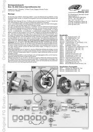
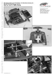
Exploded view for<br />
<strong>Leopard</strong> 2 Competition, Item N°. 67005<br />
67330 Alum.<br />
67320/11<br />
shock absorber<br />
short, Ø24, 2pcs.<br />
67320/3<br />
67320 Alum.<br />
Shock absorber<br />
long, Ø24, 2pcs.<br />
67320/15<br />
67320/5<br />
66295/100<br />
Shock<br />
absorber oil<br />
1000<br />
67160<br />
60100/2<br />
E.67005-170910<br />
67330/1<br />
67320/12<br />
67312<br />
67165<br />
67320/10<br />
67330/2<br />
6738/3<br />
6734/3<br />
67320/02<br />
67320/4<br />
67320/01<br />
67320/8<br />
67320/9<br />
67320/13<br />
67320/7<br />
6481/4<br />
67320/06<br />
67303<br />
67315<br />
67302<br />
8380/8<br />
8380/8<br />
8381<br />
8381/1<br />
8381<br />
6350/1 6350 6349<br />
6732/4<br />
8381/3 8380/3 8380/1<br />
8380/4<br />
6920/8<br />
67320/14<br />
8380/7<br />
6350<br />
8381/1<br />
8381<br />
8380/6<br />
Front tire glued<br />
67243<br />
67271<br />
60230<br />
67287<br />
6926/14<br />
6925/10<br />
67261<br />
67285<br />
67287<br />
67257<br />
6920/14<br />
6925/10<br />
6925/16<br />
6920/14 67256<br />
6925/8 7100<br />
6260/1<br />
6732/5<br />
6924/18 67260/1<br />
67260/5<br />
6929/14 8514/8<br />
6928/3<br />
1097/1<br />
66245<br />
6926/25<br />
6738/5<br />
6734/5<br />
67259<br />
6930/20<br />
67268<br />
67258<br />
6930/10<br />
7155<br />
6912/16<br />
6926/16 7154/2<br />
68327/1<br />
6920/10<br />
4493/3<br />
67240<br />
6914/9<br />
6013<br />
6734/3<br />
6924/16<br />
68423/1<br />
6738/3<br />
66245<br />
66244/1<br />
6912/16<br />
67286<br />
6924/25<br />
6920/14<br />
7100 6732/5<br />
6738/4<br />
69241<br />
67242<br />
68323<br />
6932/16<br />
1097/1 6104/1<br />
68325/1<br />
6914/13<br />
67269<br />
67266<br />
67264<br />
66226/2 66271<br />
6916/22<br />
6932/12<br />
68326<br />
66270/2<br />
68324/1<br />
66244/1<br />
6738/3<br />
6925/8<br />
6734/4<br />
6925/12<br />
67302<br />
67336<br />
6925/22<br />
67265<br />
6917/6<br />
4429/2<br />
6922/25 4466 6734/5<br />
66270/4<br />
66270/1<br />
67267<br />
6078/5<br />
6933/6<br />
6029/8 6107<br />
6926/25<br />
7475/1 6734/5<br />
6113<br />
67229<br />
10027/7<br />
6932/14<br />
7475/2<br />
1213/10<br />
6924/18<br />
67239/1<br />
6922/25
7384<br />
66218/1<br />
6464/4<br />
6464/5 6465/1<br />
6912/13<br />
6912/13<br />
6912/16<br />
6451/4<br />
6451/3<br />
6468<br />
7473/2<br />
1039<br />
6738/5<br />
6485/1<br />
6038<br />
6038<br />
6038<br />
6920/14<br />
6920/14<br />
6920/14<br />
66217<br />
6923/16<br />
6930/5<br />
6734/4 6925/25<br />
66216<br />
6490<br />
6492/1<br />
6926/10<br />
6926/10<br />
6917/16<br />
6926/40<br />
6917/16<br />
6929/4<br />
6929/4<br />
6929/4<br />
6929/14<br />
6924/20<br />
6930/20<br />
1097/1<br />
1097/1<br />
67225/1<br />
67225/2<br />
67225/3<br />
67226<br />
67227<br />
7071/1<br />
67260/2<br />
67260/4<br />
67260/5<br />
67230<br />
6204/1<br />
67335<br />
6925/18<br />
6925/18<br />
6926/25<br />
6926/25<br />
67303<br />
67312<br />
6922/14<br />
6922/14<br />
67235<br />
67236<br />
Rear tire<br />
glued<br />
67271<br />
67250<br />
6917/8<br />
6065<br />
8486/1<br />
6048<br />
67251<br />
6038 3024<br />
6738/4<br />
67245<br />
6929/20<br />
67244<br />
67151<br />
67151<br />
6916/16<br />
6916/13<br />
67247<br />
67244/1<br />
5014/5<br />
6013<br />
6013<br />
6012<br />
6912/22<br />
6916/32<br />
6036/5<br />
6932/14<br />
6932/14<br />
6932/14<br />
6932/14<br />
6926/14<br />
67238<br />
6930/5<br />
7315<br />
7315/1<br />
7316/1<br />
7472<br />
6040/5<br />
6745<br />
6745<br />
6432<br />
7317/11<br />
7318<br />
7318<br />
6926/16<br />
6926/16<br />
6299/5<br />
67298/1<br />
67298/2<br />
6299/4<br />
7332<br />
6291/3<br />
6738/4<br />
6738/5<br />
6738/4<br />
6930/5<br />
6930/5<br />
6734/4<br />
6734/4<br />
6734/4 6734/4<br />
6734/4<br />
6734/4<br />
6734/5<br />
6734/4<br />
6734/4<br />
6925/18<br />
6925/18<br />
6291/3<br />
6020<br />
6928/3<br />
67246<br />
6020<br />
6928/3<br />
6738/3<br />
6739/3<br />
5019/1<br />
6534/2<br />
1018/5<br />
6924/10<br />
6933/6<br />
6912/13<br />
6930/30<br />
6916/22<br />
6916/22<br />
60238<br />
60239<br />
60239/1<br />
6914/9<br />
6914/19<br />
6914/13<br />
6022/1<br />
66241<br />
66212<br />
6925/20<br />
6925/20<br />
6920/10<br />
67272/3 67270/3<br />
67270/2<br />
6925/12 6925/12<br />
6920/25<br />
7475/4<br />
67232<br />
67229<br />
10027/7<br />
8493/5<br />
6920/8<br />
8495<br />
8489<br />
6066/2<br />
6067/2<br />
6068<br />
8499/1<br />
8499/3<br />
6113<br />
6079/1<br />
4412<br />
7080/2<br />
7080/3<br />
67277<br />
6069/2<br />
66245<br />
6075/5<br />
6073/5<br />
6732/5<br />
6732/5<br />
6933/6<br />
6107<br />
6077/8<br />
6078/5<br />
6479/1<br />
6479/2<br />
6928/3<br />
7100<br />
6920/18<br />
6916/32<br />
67244/2
Spare parts list for Item N°. 67005<br />
Parts list for <strong>Leopard</strong> 2 Competition<br />
Update 17.09.10<br />
Item N°. Description<br />
01018/05 Alum. distance bolt Ø5x20mm, 1pce.<br />
01039 Alum. gear plate EVO/Comp., 1pce.<br />
01097/01 Guide bush with collar 6x8x7,5, 6pcs.<br />
01213/10 Steel ball Ø7 x 6,5mm, 4pcs.<br />
03024 Plastic disks, 4pcs.<br />
04412 Protective bellow for dogbones, 2pcs.<br />
04429/02 Taper disk 5mm boring, 4pcs.<br />
04466 Ball-type nipple f. alum. wishbone, 2pcs.<br />
04493/03 O-rings f. servo saver Ø6x3, 4pcs.<br />
05014/05 Bolt for battery holder, 2pcs.<br />
05019/01 Pressure spring 0,4x5x25mm, 2pcs.<br />
06012 Body bolts, 4pcs.<br />
06013 Body clips, 10pcs.<br />
06020 Collets 2,1 mm, 5pcs.<br />
06022/01 Flexible aerial and mount, 1pce.<br />
06029/08 Ball-and-socket joint for M8, 4pcs.<br />
06036/05 <strong>FG</strong> ball bearing 10x19x7 w. grease filling, 2pcs.<br />
06038 Engine mount washers, 4pcs.<br />
06040/05 <strong>FG</strong> ball bearing 10x22x6 w. grease filling, 2pcs.<br />
06048 Steel gearwheel 48 teeth big, 1pce.<br />
06065 Aluminium differential cover, 1pce.<br />
06066/02 Bevel diff. gear A, pluggable, 2pcs.<br />
06067/02 Diff. gearwheel B reinforced, 2pcs.<br />
06068 Bevel differential gear axle, 1pce.<br />
06069/02 Ball diff. axle, 1pce.<br />
06073/05 Wishbone pin hardened 6x63mm, 2pcs.<br />
06075/05 Wishbone pin hardened 6x65mm, 2pcs.<br />
06077/08 Distance bush for rear upright, 2pcs.<br />
06078/05 <strong>FG</strong> ball bearings 8x22x7 w. grease filling, 2pcs.<br />
06079/01 Ball driving axle, 1pce.<br />
06104/01 Front driving axle 57mm, 1pce.<br />
06107 Alum. square wheel driver 9,5mm/M6, 2pcs.<br />
06113 Wheel nuts M6, self-locking, 10pcs.<br />
06204/01 Mount for pull starter, 1pce.<br />
06260/01 Support for stabilizer 4mm, 2pcs.<br />
06291/03 Fastening wire f. Tuning pipe, 2pcs.<br />
06299/04 Fabric tube Ø24 x 23 f. 06299, 1pce.<br />
06299/05 Extension spring f. 06299/01, 3pcs.<br />
06349 Pendulum, 1pce.<br />
06350 Fuel tube, 1pce.<br />
06350/01 Rubber gaskets, 2pcs.<br />
06432 Steel gearwheel 18 teeth, 1pce.<br />
06451/03 Air filt. adapt.f. Zen.G230/260,CY, 1pce.<br />
06451/04 O-rings f. air filter adapt.19x1,5/ 57x2,5, 2pcs.<br />
06464/04 Foam filter, 2pcs.<br />
06464/05 Foam filter oiled, 2pcs.<br />
06465/01 Filter cover, 1pce.<br />
06468 Preliminary filter f. inlet air filter, 1pce.<br />
06479/01 Rear alum. 08 upright, left, 1pce.<br />
06479/02 Rear alum. 08 upright, right, 1pce.<br />
06481/04 O-ring 20x1,5mm, 4pcs.<br />
06485/01 Alum. eng. mount sm. 1:6/Zen. G230/260, 1pce.<br />
06490 Alum. gearwheel adapter, 1pce.<br />
06492/01 Steel gearwheel 46 teeth, 1pce.<br />
06534/02 Throttle pivot post 2,1 mm, set<br />
06732/04 Retaining washers-spring steel 4mm, 15pcs.<br />
06732/05 Retaining washers-spring steel 5mm, 15pcs.<br />
06734/03 Washers, steel 3,2mm, 15pcs.<br />
06734/04 Washers, steel 4,3mm, 15pcs.<br />
06734/05 Washers, steel 5,3mm, 15pcs.<br />
06738/03 Self-locking hexagon nut, M3, 15pcs.<br />
06738/04 Self-locking hexagon nut, M4, 15pcs.<br />
06738/05 Self-locking hexagon nut, M5, 15pcs.<br />
06739/03 Hexagon nut M3, 15pcs.<br />
06745 Shim rings 10x16x1mm, 10pcs.<br />
Item N°. Description<br />
06912/13 Counters. sheet met. screw w. Torx 4,2x13, 20pcs.<br />
06912/16 Counters. sheet met. screw w. Torx 4,2x16, 20pcs.<br />
06912/22 Counters. sheet met. screw w. Torx 4,2x22, 20pcs.<br />
06914/09 Pan-head sheet met. screw w. Torx 2,9x9,5, 15pcs.<br />
06914/13 Pan-head sheet met. screw w. Torx 2,9x13, 15pcs.<br />
06914/19 Pan-head sheet met. screw w. Torx 2,9x19, 15pcs.<br />
06916/13 Pan-head sheet met. screw w. Torx 4,2x13, 15pcs.<br />
06916/16 Pan-head sheet met. screw w. Torx 4,2x16, 15pcs.<br />
06916/22 Pan-head sheet met. screw w. Torx 4,2x22, 15pcs.<br />
06916/32 Pan-head sheet met. screw w. Torx 4,2x32, 15pcs.<br />
06917/06 Pan-head flange screw w. Torx M3x6, 10pcs.<br />
06917/08 Pan-head flange screw w. Torx M3x8, 10pcs.<br />
06917/16 Pan-head flange screw w. Torx M6x10, 5pcs.<br />
06920/08 Countersunk screw w. Torx M4x8, 10pcs.<br />
06920/10 Countersunk screw w. Torx M4x10, 10pcs.<br />
06920/14 Countersunk screw w. Torx M4x14, 10pcs.<br />
06920/18 Countersunk screw w. Torx M4x18, 10pcs.<br />
06920/25 Countersunk screw w. Torx M4x25, 10pcs.<br />
06922/14 Countersunk screw w. Torx M5x14, 10pcs.<br />
06922/25 Countersunk screw w. Torx M5x25, 10pcs.<br />
06923/16 Countersunk screw w. Torx M6x16, 10pcs.<br />
06924/10 Pan-head screw w. Torx M3x10, 10pcs.<br />
06924/16 Pan-head screw w. Torx M3x16, 10pcs.<br />
06924/18 Pan-head screw w. Torx M3x18, 10pcs.<br />
06924/20 Pan-head screw w. Torx M3x20, 10pcs.<br />
06924/25 Pan-head screw w. Torx M3x25, 10pcs.<br />
06925/08 Pan-head screw w. Torx M4x8, 10pcs.<br />
06925/10 Pan-head screw w. Torx M4x10, 10pcs.<br />
06925/12 Pan-head screw w. Torx M4x12, 10pcs.<br />
06925/16 Pan-head screw w. Torx M4x16, 10pcs.<br />
06925/18 Pan-head screw w. Torx M4x18, 10pcs.<br />
06925/20 Pan-head screw w. Torx M4x20, 10pcs.<br />
06925/22 Pan-head screw w. Torx M4x22, 10pcs.<br />
06925/25 Pan-head screw w. Torx M4x25, 10pcs.<br />
06926/10 Pan-head screw w. Torx M5x10, 10pcs.<br />
06926/14 Pan-head screw w. Torx M5x14, 10pcs.<br />
06926/16 Pan-head screw w. Torx M5x16, 10pcs.<br />
06926/25 Pan-head screw w. Torx M5x25, 10pcs.<br />
06926/40 Pan-head screw w. Torx M5x40, 10pcs.<br />
06928/03 Headless pin w. Torx M3x3, 15pcs.<br />
06929/04 Headless pin w. Torx M4x4, 15pcs.<br />
06929/14 Headless pin w. Torx M4x14, 15pcs.<br />
06929/20 Headless pin w. Torx M4x20, 15pcs.<br />
06930/05 Headless pin w. Torx M5x5, 15pcs.<br />
06930/10 Headless pin w. Torx M5x10, 15pcs.<br />
06930/20 Headless pin w. Torx M5x20, 15pcs.<br />
06930/30 Headless pin w. Torx M5x30, 15pcs.<br />
06932/12 Socket head cap screw w. Torx M4x12, 10pcs.<br />
06932/14 Socket head cap screw w. Torx M4x14, 10pcs.<br />
06932/16 Socket head cap screw w. Torx M4x16, 10pcs.<br />
06933/06 Headless pin w. Torx M6x6, 15pcs.<br />
07071/01 Stabilizer 5mm rear, 1pce.<br />
07080/02 Balls f. driving shaft, 6pcs.<br />
07080/03 Distance disks, 4pcs.<br />
07100 Adjusting clips for front axle, 16pcs.<br />
07154/02 Body mount 65mm, adjustable, 1pce.<br />
07155 Body mount 54mm, adjustable, 1pce.<br />
07315 Clutch block carrier, 1pce.<br />
07315/01 Screw for carrier/Zenoah, 1pce.<br />
07316/01 Tuning clutch blocks, 2pcs.<br />
07317/11 Clutch spring Ø2,7/G230/240/260/270, 1pce.<br />
07318 Dowel screws f.clutch blocks/Zenoah, 2pcs.<br />
07332 Silencer gasket, 2pcs.<br />
07384 <strong>FG</strong> Zenoah engine G260RC<br />
07472 Tuning clutch bell hardened, 1pce.<br />
07473/02 Engine flange f. engine quick fix., 1pce.<br />
07475/01 Alum. joint ball Ø 5/10x15mm, 2pcs.<br />
07475/02 Alum. joint ball Ø10x10,75mm, 2pcs.<br />
07475/04 Alum. joint ball Ø 10x13mm, 2pcs.<br />
08380 Fuel tank with quick acting closure, 1pce.<br />
08380/01 Tank, 1pce.<br />
Item N°. Description Item N°. Description<br />
08380/03 Fastening pin f. tank cap, 1pce.<br />
08380/04 Torsion spring f. tank cap, 1pce.<br />
08380/06 Tank gasket, 2pcs.<br />
08380/07 Safety ring, 2pcs.<br />
08380/08 Tank cap/pressure plate w. ventilation, each 1pce.<br />
08381 Fuel hose black 1,5m, 1pce.<br />
08381/01 90° connection, 2pcs.<br />
08381/03 Vent nipple M5, 1pce.<br />
08486/01 Alum. differential housing 1:5/1:6, 1pce.<br />
08489 O-rings, 2pcs.<br />
08493/05 <strong>FG</strong> ball bearing 15x28x7w. grease filling, 2pcs.<br />
08495 Distance disks f.alloy differential, 4pcs.<br />
08499/01 Needle bearing for differential, 2pcs.<br />
08499/03 Steel bush 8x12x5, 2pcs.<br />
08514/08 Collet set 4mm, 4pcs.<br />
09438 Hydr. brake f. front a. rear axle, set<br />
10027/07 Ball-and-sock. joint 10mm M7, length., 4pcs.<br />
60100/02 Rear spoiler white, 1pce.<br />
60230 Front bumper Baja, 1pce.<br />
60238 Plug protection, 1pce.<br />
60239 Plastic brace long, 2pcs.<br />
60239/01 Plastic brace short, 2pcs.<br />
66212 Alum. connection rod gear 4WD, 1pce.<br />
66216 Tun. gear shaft hardened 4WD, 1pce.<br />
66217 Steel gear wheel 14t. narrow, 1pce.<br />
66218/01 Basic body f. inlet silencer, 1pce.<br />
66226/02 Hexagon nut M10 left, 2pcs.<br />
66241 Receiver box 4WD, 1pce.<br />
66244/01 Ball-and-socket joint 7mm f. M4, 30mm, 8pcs.<br />
66245 Steel ball 7mm, 4pcs.<br />
66270/01 Front alum. upright right/left 4WD, 1pce.<br />
66270/02 Front alum. steering lever 4WD, 1pce.<br />
66270/04 Plastic steering stop shortened, 2pcs.<br />
66271 Ball bearing 17x26x7, 2pcs.<br />
66295/100 Oil for shock absorber 1000, 100ml, 1pce.<br />
67151 ABS splash guards le./ri. <strong>Leopard</strong>, 1pair<br />
67160 Body <strong>Leopard</strong> 2WD, 1pce.<br />
67165 Model stickers <strong>Leopard</strong> 2WD, set<br />
67209/05 Mini Pin M/OR tires, Leo wheel white, glued, 2pcs.<br />
67213/06 Mini-Block H/OR tir., Leo wheel white, glued, 2pcs.<br />
67225/01 Alum. wishbone mount 2°, left, 1pce.<br />
67225/02 Alum. wishbone mount 2°, right, 1pce.<br />
67225/03 Aluminium adjustment key 2°, 2pcs.<br />
67226 Rear lower alum. wishbone, <strong>Leopard</strong> 2, 1pce.<br />
67227 Wishbone pin hardened 6x85mm, 2pcs.<br />
67229 Turnbuckle right/left M7 x 102mm, 2pcs.<br />
67230 Rear alum. damper plate, <strong>Leopard</strong>, 1pce.<br />
67232 Aluminium ball collet Ø10x15mm, hole 6mm, 2pcs.<br />
67235 Alum. rear axle mount left <strong>Leopard</strong>, 1pce.<br />
67236 Alum. rear axle mount right <strong>Leopard</strong>, 1pce.<br />
67238 Alum. gear flange engine mount <strong>Leopard</strong>, 1pce.<br />
67239/01 Alum. distance f. servo saver <strong>Leopard</strong> 2, 1pce.<br />
67240 Alum. servo retainer, 2-parts, fixed, 2pcs.<br />
67242 Steering rod r./l., M4 x 85mm, 2pcs.<br />
67243 Aluminium battery brace 87mm, 1pce.<br />
67244 Roll cage short, 1pce.<br />
67244/01 Plastic brace Ø10 x 60mm, 2pcs.<br />
67244/02 Plastic brace Ø10 x 80mm, 2pcs.<br />
67245 Aluminium distance Ø10 x 70mm, 1pce.<br />
67246 Throttle rods <strong>Leopard</strong> 2, set<br />
67247 Distance bolt Ø8 x 38mm, 2pcs.<br />
67250 Wing mount rear Leo, 2pcs.<br />
67251 Adjustment part wing mount, 2pce.<br />
67256 Aluminium front axle mount A <strong>Leopard</strong> 2, 1pce.<br />
67257 Aluminium front axle mount B <strong>Leopard</strong> 2, 1pce.<br />
67258 Aluminium front axle mount C <strong>Leopard</strong> 2, 1pce.<br />
67259 Aluminium spring deflection block <strong>Leopard</strong> 2, 2pcs.<br />
67260/01 Steel ball Ø7 x 5mm, hole 4mm, 2pcs.<br />
67260/02 Steel ball Ø7 x 5mm, hole 5mm, 2pcs.<br />
67260/04 Aluminium collet 5mm, 2pcs.<br />
67260/05 Ball-and-socket joint 7mm, 4pcs.<br />
67261 Front stabilizer 4mm, <strong>Leopard</strong> 2, set<br />
67264 Alum. bearing adapter f. front driving axle, 1pce.<br />
67265 Front lower alum. wishbone <strong>Leopard</strong>, 1pce.<br />
67266 Front upper alum. wishbone <strong>Leopard</strong> 2, 1pce.<br />
67267 Wishbone thread rod M10/M8 x 108mm, 2pcs.<br />
67268 Wishbone pin hardened Ø6 x 88mm, 2pcs.<br />
67269 Wishbone pin hardened Ø6 x 60mm, 2pcs.<br />
67270/02 CFRP chassis stiffening f. <strong>Leopard</strong>, 2pcs.<br />
67270/03 Insert bush f. chassis stiffening <strong>Leopard</strong>, 4pcs.<br />
67271 Alum. chassis <strong>Leopard</strong> 2, 1pce.<br />
67277 Ball driving shaft rear 130,5mm, 1pce.<br />
67285 Reinforcing plate f. fr. axle <strong>Leopard</strong> 2, 1pce.<br />
67286 Alum. front axle support <strong>Leopard</strong> 2 , 1pce.<br />
67287 Front alum. damper plate, <strong>Leopard</strong>, 1pce.<br />
67298 <strong>FG</strong> Steel-Power Tuning pipe <strong>Leopard</strong> 2, compl., set<br />
67298/01 <strong>FG</strong> Steel-Power Tuning pipe <strong>Leopard</strong> 2, compl., 1pce.<br />
67298/02 Manifold f. Tuning pipe 67298/01, black, 1pce.<br />
67302 Damper spring orange, 2,4x105mm, 2pcs.<br />
67303 Damper spring red, 2,5x105mm, 2pcs.<br />
67312 Damper spring orange, 2,4x40mm, 2pcs.<br />
67315 Plastic spring guide Ø25, 2pcs.<br />
67320 Aluminium shock absorber long, Ø24, 2pcs.<br />
67320/01 Alum. shock abs. housing Ø24mm , long, 1pce.<br />
67320/02 Threaded piston rod Ø4,5 x 117mm, 1pce.<br />
67320/03 Lower aluminium shock absorber seal, Ø24, 1pce.<br />
67320/04 Upper aluminium shock absorber seal, Ø24, 1pce.<br />
67320/05 Plastic adjusting ring Ø24, 1pce.<br />
67320/06 Alum. spring plate Ø24, 1pce.<br />
67320/07 Plastic bush Ø4,5/Ø7 x 4mm, 4pcs.<br />
67320/08 Plastic guide disc, 4pcs.<br />
67320/09 Volume compensation Ø20mm, 4pcs.<br />
67320/10 Plastic shock piston, 2pcs.<br />
67320/11 O-ring Ø22 x 1,5mm, 4pcs.<br />
67320/12 O-ring Ø24 x 1,5mm, 4pcs.<br />
67320/13 Sealring Ø4,5mm, 2pcs.<br />
67320/14 Lower shock retaining, reinforced, 4pcs.<br />
67320/15 Plastic bush Ø5 / Ø7 x 6,5mm, 4pcs.<br />
67330 Alum. shock absorber short, Ø24mm, 2pcs.<br />
67330/01 Alum. shock abs. housing Ø24mm, short, 1pce.<br />
67330/02 Threaded piston rod Ø4,5 x 95mm, 1pce.<br />
67335 CFRP shock absorb. protect., rear, 1pce.<br />
67336 Shock absorb. protect. le./ri., 2pcs.<br />
68323 Servo saver A/B, 1pce.<br />
68324/01 Servo saver axle 2010, 1pce.<br />
68325/01 Servo saver spring blue 2,4mm, 1pce.<br />
68326 Nut M10 f. servo saver, 1pce.<br />
68327/01 Tension sleeve f. servo saver 2010, 1pce.<br />
68423/01 Alum. servo saver, part B, 1pce.<br />
69241 Plastic servo mount small, 1pce.
Ersatzteilliste für<br />
7300/9 Zenoahmotor G230RC/04<br />
7384 Zenoahmotor G260RC<br />
7301/8 Kurbelgehäuse A+B, 1 St.<br />
7303/8 Dichtring, 2 St.<br />
7304/2 Kugellager, 2 St.<br />
7305/8 Kurbelgehäusedichtung, 1 St.<br />
7306/8 Zylinder-Fußdichtung, 1 St.<br />
7307/9 Zylinder G230/04,1St.<br />
7307/10 Tun.-Zylinder f. <strong>FG</strong> Zenoah02 ,1St.<br />
7308/9 Kolben G230/04, 1 St.<br />
7309/9 Kolbenring G230/04, 1 St.<br />
7310 Kolbenbolzen, 1 St.<br />
7311 Kolbenbolzensicherung, 2 St.<br />
7312 Nadellager kompl., 1 St.<br />
7312/1 Zentrierscheiben f. Nadellager, 2 St.<br />
7313/8 Kurbelwelle kompl., 1 St.<br />
7313/1 Keil für Kurbelwelle, 1 St.<br />
7314 Sechskantmutter, 1 St.<br />
7315 Mitnehmer f. Kuppl.-Backen, 1 St.<br />
7315/1 Schraube f.Mitnehmer, 1 St.<br />
7316 Kupplungsbacken, 2 St.<br />
7317/8 Kupplungsfeder, 1 St.<br />
7318 Passschrauben f. K.-Backen 2 St.<br />
7319/8 Lüfterrad/G230/260RC,CY, 1St.<br />
7323/8 Seilzugstartv. kpl./G230/260RC,CY,1St<br />
7323/9 Startergehäuse/G230/260RC,CY, 1St.<br />
7323/10 Federkassette /G230/260RC,CY, 1St.<br />
7323/11 Seilrolle/G230/260RC,CY, 1St.<br />
7323/12 Starterseil/G230/260RC,CY, 1St.<br />
7323/13 Startergriff/G230/260RC,CY, 1St.<br />
7323/14 Starterklinke/G230/260RC,CY, 1St.<br />
7323/15 Druckfeder/G230/260RC,CY, 1St.<br />
7323/16 Schraube/ Scheib./ G230/260RC,CY, 3St.<br />
7326/8 Sicherungsring/G230/260RC,CY, 1St.<br />
7328/2 Zündkerzenstecker, 1 St.<br />
7328/8 Zündspule/ G230/260RC,CY, 1St.<br />
7330/8 Schrauben f.Schalld.M5x60/Zen.,CY 2St.<br />
7332 Schalldämpferdichtung /Zenoah,CY, 2St.<br />
7334/8 Schraubensatz-Motor, Set<br />
7335 Dichtung f. Isolator /Zenoah,CY, 1St.<br />
7336 Isolator, 1 St.<br />
7337 Dichtung f. Vergaser /Zenoah,CY, 1St.<br />
7339/8 Vergaserschrauben/ G230/260RC,CY, 2St.<br />
7340/8 Aus-Schalter/ G230/260RC,CY, 1St.<br />
7341/8 Motorgehäuse A, 1 St.<br />
7342/8 Motorgehäuse B, 1 St.<br />
7343/8 Zündkerze/ G230 RC,CY, 1St.<br />
7344/8 Kabeldurchführung/ G230/260RC,CY, 1St.<br />
7354/8 Distanzstück/ G230 RC,CY, 1St.<br />
7355/8 Vergaser/ G230/260RC,CY, 1St.<br />
7356/8 Luftfilter/G230/260RC,CY,kompl., 1St.<br />
7357 Luftfilter-Einsatz / Zenoah,CY, 2St.<br />
7361/8 Vollgasdüsennadel/ Feder, 2 St.<br />
7362/9 Leerlaufdüsennadel/ Feder G230/04, 2 St.<br />
7363 Membrane-Satz, 2 St.<br />
7364 Vergaserdeckel, 1 St.<br />
7365 Standgasschraube/ Feder, 2 St.<br />
7365/9 Standgasschr./Feder G230/260RC04, 2St.<br />
7366/8 Drosselklappenwelle m. Schraube, 2 St.<br />
7367/8 Drosselklappe, 1 St.<br />
7368 Schenkelfeder, 1 St.<br />
7370 Membrane-Satz, 2 St.<br />
7371 Kunststoffteil m. Vergaser-Nippel, 1 St.<br />
7372 Metallteil f. Pumpe, 1 St.<br />
7372/1 Schrauben für Metallteil, 4 St.<br />
7373 Pumpe, 1 St.<br />
7374 Vergaserhebel, 1 St.<br />
7375 Schraube f. Vergaserhebel, 1 St.<br />
7377/8 Choke-Welle m. Schraube, 2 St.<br />
7378/8 Choke-Klappe, 1 St.<br />
7379/8 Choke-Hebel, 2 St.<br />
7385/1 Zylinder 26 ccm, 1 St.<br />
7385/2 Kolben 26 ccm, 1 St.<br />
7385/3 Kolbenring 26 ccm, 1 St.<br />
7385/4 Kolbenbolzen 26 ccm, 1 St.<br />
8344/1 Kuppl.-Flansch Zenoah liegend, 1 St.<br />
8345 Kuppl.-Flansch Zenoah stehend, 1 St.<br />
Spare parts list for<br />
7300/9 Zenoah engine G230RC/04<br />
7384 Zenoah engine G260RC<br />
7301/8 Crank case housing A+B, 1 pce.<br />
7303/8 Seal ring, 2 pcs.<br />
7304/2 Bearings, 2 pcs.<br />
7305/8 Crankshaft gasket, 1 pce.<br />
7306/8 Cylinder gasket, 1 pce.<br />
7307/9 Cylinder G230/04, 1 pce.<br />
7307/10 Tun.-Cylinder f. <strong>FG</strong> Zenoah 02, 1 pce.<br />
7308/9 Piston G230/04, 1 pce.<br />
7309/9 Piston ring G230/04, 1 pce.<br />
7310 Gudgeon pin, 1 pce.<br />
7311 Gudgeon pin clips, 2 pcs.<br />
7312 Needle bearing, 1 pce.<br />
7312/1 Spacer washer, 2 pcs.<br />
7356/8<br />
7317/8<br />
7316<br />
7339/8<br />
7357<br />
7362/9<br />
7315/1<br />
7315<br />
7354/8<br />
7313/8 Crankshaft complete, 1 pce.<br />
7313/1 Key for crankshaft, 1 pce.<br />
7314 Hexagon nut, 1 pce.<br />
7315 Clutch block carrier, 1 pce.<br />
7315/1 Screw for carrier, 1 pce.<br />
7316 Clutch blocks, 2 pcs.<br />
7317/8 Clutch spring, 1 pce.<br />
7318 Dowel screws f. clutch blocks, 2 pcs.<br />
7319/8 Cooling fan/G230/260RC,CY, 1pce.<br />
7323/8 Pull start unit/G230/260RC,CY, 1pce.<br />
7323/9 Starter hous./G230/260RC,CY, 1pce.<br />
7323/10 Spring assem./G230/260RC,CY, 1pce.<br />
7323/11 Rope pulley/G230/260RC,CY, 1pce.<br />
7323/12 Rope/G230/260RC,CY, 1pce.<br />
7323/13 Starter handle/G230/260RC,CY, 1pce.<br />
7323/14 Starter ratchet/G230/260RC,CY, 1pce.<br />
7323/15 Press. spring/G230/260RC,CY, 1pce.<br />
7323/16 Screw,disks/G230/260RC,CY, 3pcs.<br />
7326/8 Securing ring/G230/260RC,CY, 1pce.<br />
7328/2 Spark plug cap, 1pce.<br />
7328/8 Ignition coil/G230/260RC,CY, 1 pce.<br />
7330/8 Scews f.silencer M5x60/Zen.,CY,2pcs.<br />
7332 Silencer gasket /Zenoah,CY, 2pcs.<br />
7334/8 Screw set engine<br />
7335 Insulator gasket/Zenoah,CY, 1pce.<br />
7336 Insulator, 1 pce.<br />
7337 Carburetor gasket/Zenoah,CY, 1pce.<br />
7370<br />
7361/8<br />
7372<br />
7366/8 7367/8<br />
7368<br />
7365<br />
7365/9<br />
7373<br />
7355/8<br />
7371<br />
7364<br />
7326/8<br />
7372/1<br />
7377/8<br />
7378/8<br />
7337<br />
7363<br />
7379/8<br />
7374/7375<br />
7336<br />
ohne Abb.<br />
7328/2<br />
Kerzenstecker<br />
7335<br />
7309/9<br />
7385/3<br />
7304/2<br />
7306/8<br />
7312/1<br />
7339/8 Screws f.carb./G230/260RC,CY, 2pcs.<br />
7340/8 Circuit breaker/G230/260RC,CY,1pce.<br />
7341/8 Engine housing A, 1 pce.<br />
7342/8 Engine housing B, 1 pce.<br />
7343/8 Spark plug G230 RC,CY, 1pce.<br />
7344/8 Cable bush./G230/260RC,CY, 1pce.<br />
7354/8 Spacer block/G230RC,CY, 1 pce.<br />
7355/8 Carburetor/G230/260RC,CY, 1pce.<br />
7356/8 Air filter/G230/260RC,CY, 1pce.<br />
7357 Air filter foam, Zenoah,CY 2pcs.<br />
7361/8 Needle(full-speed)/ spring, 2 pcs.<br />
7362/9 Needle(idle speed)/spring<br />
G230/04,2pcs.<br />
7363 Diaphragm, 2 pcs.<br />
7364 Carburetor cover, 1 pce.<br />
7365 Throttle screw /spring, 2 pcs.<br />
7366/8 Valve, 1 pce.<br />
7368 Leg spring, 1 pce.<br />
7370 Diaphragm set, 2 pcs.<br />
7371 Plastic part with carb. nipple, 1 pce.<br />
7372 Metal part f. pump, 1 pce.<br />
7372/1 Screws f. metal part, 4 pcs.<br />
7373 Pump, 1 pce.<br />
7374 Carburetor arm, 1 pce.<br />
7375 Screw f. carburetor arm, 1 pce.<br />
7377/8 Choke shaft w. screw, 2 pcs.<br />
7378/8 Choke flap, 1 pce.<br />
7303/8<br />
7313/9 7303/8<br />
7301/8<br />
7318 8344/1<br />
7319/8<br />
7305/8<br />
8345<br />
7334/8<br />
7301/8<br />
7308/9<br />
7385/2<br />
7343/8<br />
7310<br />
7385/4<br />
7312<br />
7313/8<br />
7342/8<br />
7307/9<br />
7307/10<br />
7385/1<br />
7311<br />
7332<br />
7330/8<br />
7334/8<br />
7340/8<br />
7344/8<br />
7341/8<br />
7379/8 Choke lever, 2 pcs.<br />
7385/1 Cylinder 26 ccm, 1 pce.<br />
7385/2 Piston 26 ccm, 1 pce.<br />
7385/3 Piston ring 26 ccm, 1 pce.<br />
7385/4 Gudgeon pin 26 ccm, 1 pce.<br />
8344/1 Coupling flange Solo/Zeno horizontal<br />
8345 Coupling flange Zenoah vertical<br />
7323/12<br />
<strong>FG</strong> <strong>Modellsport</strong> <strong>GmbH</strong><br />
Spanningerstr. 2<br />
73650 Winterbach-Germany<br />
Phone: +49 7181 9677-0<br />
Fax: +49 7181 9677-20<br />
info@fg-modellsport.de<br />
www.fg-modellsport.de<br />
7334/8<br />
7323/13<br />
7328/8<br />
7323/10<br />
7323/9<br />
7334/8<br />
7323/16<br />
7314<br />
EL.7300-9-280906<br />
7323/15<br />
7323/14<br />
7323/11