Sensorless Rotor Position Estimation of Switched Reluctance Motor ...
Sensorless Rotor Position Estimation of Switched Reluctance Motor ...
Sensorless Rotor Position Estimation of Switched Reluctance Motor ...

Create successful ePaper yourself
Turn your PDF publications into a flip-book with our unique Google optimized e-Paper software.
International Journal <strong>of</strong> S<strong>of</strong>t Computing and Engineering (IJSCE)<br />
ISSN: 2231-2307, Volume-3, Issue-2, May 2013<br />
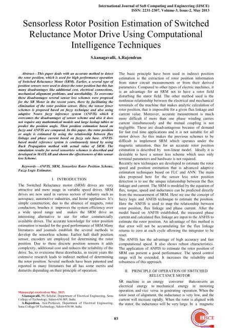
<strong>Sensorless</strong> <strong>Rotor</strong> <strong>Position</strong> <strong>Estimation</strong> <strong>of</strong> <strong>Switched</strong><br />
<strong>Reluctance</strong> <strong>Motor</strong> Drive Using Computational<br />
Intelligence Techniques<br />
S.kanagavalli, A.Rajendran<br />
Abstract—This paper deals with an accurate method to detect<br />
the rotor position, which is used for high performance operation<br />
<strong>of</strong> <strong>Switched</strong> <strong>Reluctance</strong> <strong>Motor</strong> (SRM). Earlier, a several type <strong>of</strong><br />
position sensors were used to detect the rotor position but this has<br />
many disadvantages like additional cost, electrical connections,<br />
mechanical alignment problems, and unreliability. To overcome<br />
these disadvantages several sensor less schemes were proposed<br />
for the SR <strong>Motor</strong> in the recent years, there by facilitating the<br />
elimination <strong>of</strong> the rotor position sensor. Here, the sensor fewer<br />
schemes is proposed based on fuzzy technique and also using<br />
adaptive Neuro fuzzy inference system (ANFIS) which it<br />
overcomes the disadvantages <strong>of</strong> sensor scheme and also it does<br />
not require any mathematical models and large lookup tables to<br />
predict the position angle. Then position estimation based on<br />
fuzzy and ANFIS are compared. In this paper, the rotor position<br />
or angle is estimated by using the relationship between flux<br />
linkage and phase current based on fuzzy rule base. ANFISbased<br />
model reference system is continuously tuned by using<br />
Back Propagation method with actual value <strong>of</strong> SRM. The<br />
simulation results for novel sensorless schemes is described and<br />
developed in MATLAB and shown the effectiveness <strong>of</strong> this sensor<br />
less Scheme.<br />
Keywords—ANFIS, SRM, <strong>Sensorless</strong> <strong>Rotor</strong> <strong>Position</strong> Scheme,<br />
Fuzzy Logic Estimator.<br />
I. INTRODUCTION<br />
The <strong>Switched</strong> <strong>Reluctance</strong> motor (SRM) drives are very<br />
attractive and more usage in variable speed drives. SRM<br />
drives are now used in various sectors <strong>of</strong> industry such as<br />
aerospace, automotive industries, and home appliances. It’s<br />
simple construction, due to the absence <strong>of</strong> magnets, rotor<br />
conductors, brushes it improves the system efficiency over<br />
a wide speed range and makes the SRM drive an<br />
interesting alternative to use for other commercially<br />
available drives. The accurate knowledge for rotor position<br />
estimation is needed for the good performance <strong>of</strong> SRM.Many<br />
literatures and journals establish the several methods to<br />
develop the sensorless scheme. Earlier hall shaft position<br />
sensor, encoders are employed for determining the rotor<br />
position. Due to these discrete position sensors it adds<br />
complexity, additional cost and reduces the reliability <strong>of</strong> the<br />
drive. So, to overcome these drawbacks, in recent years the<br />
extensive research leads to indirect method <strong>of</strong> determining<br />
the rotor position. Several methods have been patented and<br />
reported in many literatures but all has some merits and<br />
demerits depending on their principle <strong>of</strong> operation.<br />
Manuscript received on May, 2013.<br />
S.kanagavalli, PG Scholar, Department <strong>of</strong> Electrical Engineering, Sona<br />
College <strong>of</strong> Technology, Salem-636 005, India.<br />
A.Rajendran, Asst.Pr<strong>of</strong>essor, Department <strong>of</strong> Electrical Engineering,<br />
Sona College Of Technology, Salem-636 00, India.<br />
The basic principle have been used in indirect position<br />
estimation is the extraction <strong>of</strong> rotor position information<br />
from stator circuit measurements or from their derived<br />
parameters. Compared to other types <strong>of</strong> electric machines, it<br />
is an advantage for an SRM not to have a rotor field<br />
disturbing the stator field. The other method used is the<br />
nonlinear relationship between the electrical and mechanical<br />
terminals <strong>of</strong> the machine that makes analytic calculation <strong>of</strong><br />
rotor position, that is impossible for a given flux linkage and<br />
current value. Moreover, accurate measurement is much<br />
more difficult if more than one phase winding carries<br />
current simultaneously and the mutual coupling is not<br />
negligible. These are disadvantageous because <strong>of</strong> demand<br />
for fast real time applications and it is not suitable for all<br />
motor drives .So this makes the previous schemes to be<br />
difficult to implement SRM which operates under the<br />
magnetic saturation, thus for an accurate rotor position<br />
estimation is described by non-linear model. Ideally it is<br />
desirable to have a sensor less scheme which uses only<br />
terminal parameters and hardware is not required.<br />
Recently new techniques are developed to estimate the rotor<br />
speed and position estimation that is advanced adaptive<br />
estimation techniques based on FLC and ANN. The main<br />
idea proposed here for the sensor less rotor position<br />
detection is to use the unique relationship between the flux<br />
linkage and current. The SRM is modeled by the equation <strong>of</strong><br />
flux, torque, speed and inductance can be predicted directly<br />
from the measurement <strong>of</strong> SRM. Here we use the concept <strong>of</strong><br />
fuzzy logic and ANFIS technique to estimate the position.<br />
Here the ANFIS is used to map the relationship between<br />
rotor position, flux linkage and phase current. After the<br />
model based on ANFIS established, the measured phase<br />
current and calculated flux linkage are input to the ANFIS to<br />
estimate the rotor position. An advantage <strong>of</strong> this method is<br />
that error will not be accumulating for the flux linkage<br />
returns to zero at each cycle allowing the integrator to be<br />
reset.<br />
The ANFIS has the advantage <strong>of</strong> high accuracy and fast<br />
computational speed. It also shows robust characteristics.<br />
The application <strong>of</strong> ANFIS to estimate the rotor position <strong>of</strong><br />
SRM can present a good performance. The speed control<br />
range will be extended. It increases the reliability and<br />
robustness <strong>of</strong> this approach.<br />
II. PRINCIPLE OF OPERATION OF SWITCHED<br />
RELUCTANCE MOTOR<br />
SR machine is an energy converter thatconverts an<br />
electrical energy to mechanical energy in motoring<br />
operation, and vice versa in generating operation. When the<br />
rotor isout <strong>of</strong> alignment, the inductance is very low, and the<br />
current will increase rapidly. When the rotor is aligned with<br />
the stator, the inductance will be very large. In a magnetic<br />
83
<strong>Sensorless</strong> <strong>Rotor</strong> <strong>Position</strong> <strong>Estimation</strong> <strong>of</strong> <strong>Switched</strong> <strong>Reluctance</strong> <strong>Motor</strong> Drive Using Computational Intelligence<br />
Techniques<br />
circuit, the rotor always prefers to come to the<br />
minimum reluctance position during excitation. The torque<br />
produced in an SR machine when a phase is excited by<br />
applying a voltage, then the current in the coil produces a<br />
magnetic flux through its stator poles. This flux flows<br />
through the pair <strong>of</strong> nearest rotor poles and there exists<br />
magnetic reluctance. The reluctance <strong>of</strong> the flux path is at<br />
itsminimum in the aligned position and maximum in the<br />
unaligned position. The variable reluctance Principle is the<br />
tendency <strong>of</strong> the rotor to align itself to the minimum<br />
reluctance position. When a phase is excited, the pair <strong>of</strong><br />
nearest rotor poles is attracted to align themselves to the<br />
excited stator poles. Thus, torque is produced.Note that the<br />
rotor poles <strong>of</strong> an SR machine do not require magnetic<br />
poles to produce torque, the radial magnetic attraction in<br />
SR machine becomes ten times larger than the<br />
circumference forces produced by an induction machine<br />
position. However, as soon as the rotor is displaced to either<br />
side <strong>of</strong> the unaligned position, there appears a torque and<br />
attracts towards the next aligned position.The torque is<br />
proportional to the square <strong>of</strong> the current; hence the current<br />
can be unipolar to produce unidirectional torque. The<br />
direction <strong>of</strong> rotation can be reversed by changing the<br />
sequence <strong>of</strong> stator excitation which is a simple operation<br />
.Torque and speed control is achieved with converter<br />
control.<br />
Fig.1 Variation <strong>of</strong> <strong>Reluctance</strong> with respect to <strong>Rotor</strong> <strong>Position</strong><br />
III. PRINCIPLE OF OPERATION OF THE PROPOSED<br />
SRM SENSORLESS SCHEME<br />
The fundamental principle <strong>of</strong> operation <strong>of</strong> a SRM is based<br />
on the variation in flux linkage with the change in the<br />
angular position <strong>of</strong> the rotor and phase current. The<br />
proposed sensor less scheme based on the fuzzy based<br />
rotorposition estimator model <strong>of</strong> the SRM drive. The block<br />
diagram <strong>of</strong> the proposed sensor less scheme isshown in<br />
Fig.2.<br />
obtained in MATLAB scope. This angle is refined by using<br />
the low pass filter. The estimated angle is given to the<br />
inverter for the operation <strong>of</strong> SRM simultaneously the speed<br />
is compared with the reference speed. This fuzzy based<br />
model is implemented in MATLAB. Then the simulated<br />
result is compared with the experimental results to verify the<br />
effectiveness <strong>of</strong> the proposed scheme.<br />
A. <strong>Rotor</strong> <strong>Position</strong> <strong>Estimation</strong> Using Flux Linkage<br />
Calculation<br />
The flux linkage estimator plays a vital role for rotor<br />
position estimation. The quantity flux is generated by flux<br />
linkage estimator block, which calculates flux linkage based<br />
on the phase voltage and current in the active phase<br />
winding. The flux-linkage <strong>of</strong> any phase is computed by<br />
using Faraday’s law from<br />
(V IR) dt(1)<br />
The calculation <strong>of</strong> flux linkages by equation, helpful in<br />
computing estimated angle for the operation <strong>of</strong> sensor less<br />
SRM drive.<br />
IV. ROTOR POSITION ESTIMATION OF SRM USING<br />
FUZZY<br />
To model a fuzzy rotor position estimator for SRM, the<br />
SRM magnetization curve (Flux linkage-current-rotor<br />
position) termed a fuzzy rule base where the several rotor<br />
position data’s are stored in fuzzy rule-base tables, the<br />
position information can be taken from the rule base tables<br />
during operation. This rule base table provides several<br />
values <strong>of</strong> rotor position from the inputs <strong>of</strong> the fuzzy model.<br />
The generated fuzzy rule base is used for mapping the input<br />
values <strong>of</strong> flux linkage and current to output value <strong>of</strong> rotor<br />
position in terms <strong>of</strong> an angle. A variable in fuzzy logic has<br />
sets <strong>of</strong> values, which are characterized by linguistic labels,<br />
such as SMALL, MEDIUM, and LARGE etc. These labels<br />
are represented numerically by fuzzy sets. Each set is again<br />
characterized by membership function varies from 0 to 1.<br />
Thus fuzzy sets can be viewed as mathematical<br />
representation <strong>of</strong> linguistic values. Crisp value is the<br />
member <strong>of</strong> a fuzzy set, with a degree <strong>of</strong> membership varying<br />
from 0 (non-member) to 1 (full member). Fuzzy logic<br />
system can be simply represented into four parts: the<br />
fuzzifier, the rule base, the interference engine and the<br />
defuzzifier. During simulation estimated angle is compared<br />
with measured angle produces angle error and then fuzzy<br />
rule base has been updated according to error.In this case,<br />
the input domains are flux linkage and current are defined to<br />
have a domain <strong>of</strong> 0–1 and 0–20 A respectively. Similarly,<br />
the domain <strong>of</strong> the angle is defined as 0–30 degrees. Here the<br />
fuzzy sets were chosen to be isosceles triangular shapes.<br />
Fig.2 Block Diagram <strong>of</strong> <strong>Sensorless</strong> Control <strong>of</strong> SRM with Fuzzy/ANFIS<br />
<strong>Rotor</strong> <strong>Position</strong> Estimator<br />
It consists <strong>of</strong> PID controller, Inverter, Flux Angle Estimator.<br />
The measured current and voltage <strong>of</strong> SRM is used in Flux<br />
Estimator to produce flux linkage. The phase current and<br />
flux linkage is used as the input for fuzzy angle estimator<br />
that produces the estimated angle. In ANFIS, the data’s are<br />
trained and tested with actual value and error is calculated.<br />
Then it is given to the fuzzy. Then estimated angle is<br />
Fig.3Membership functions for Ψ, I and θ<br />
84
International Journal <strong>of</strong> S<strong>of</strong>t Computing and Engineering (IJSCE)<br />
ISSN: 2231-2307, Volume-3, Issue-2, May 2013<br />
A. Results <strong>of</strong> <strong>Position</strong> <strong>Estimation</strong> Using Fuzzy<br />
Fig.4 SIMULINK model <strong>of</strong> rotor position <strong>Estimation</strong> <strong>of</strong> SRM using Fuzzy<br />
Experimental results <strong>of</strong> SRM drive using fuzzy are<br />
discussed in this section. The results show that the proposed<br />
fuzzy based sensor less scheme is estimating the rotor<br />
position with low error. In simulation model <strong>of</strong> sensor less<br />
scheme inverter is used and given to the SRM for the<br />
operation. The torque, speed, phase current and voltage are<br />
taken from the measured value <strong>of</strong> SRM. From the measured<br />
value <strong>of</strong> speed we calculate the actual angle. By taking the<br />
current and voltage by using the fuzzy estimator we<br />
calculate the flux linkage. Using the input <strong>of</strong> flux linkage<br />
and current given to the fuzzy angle estimator and estimated<br />
angle is calculated. Then the estimated angle and actual<br />
angle is compared and then error is saturated. The<br />
simulation results are scoped. Finally, the results are<br />
matched with experimental results. Simulated and<br />
experimental results have been verified successfully at low<br />
and high speed operations.<br />
B. Performance <strong>of</strong> sensor less scheme at high speed= 4000<br />
rpm<br />
V. ROTOR POSITION ESTIMATION OF SRM USING<br />
ANFIS<br />
The ANFIS is a Sugeno adaptive network based fuzzy<br />
inference system. There are two-input flux linkage, current<br />
and one-output rotor position. Three membership functions<br />
are given for each input.. Then the rule base contains 9<br />
fuzzy if-then rules <strong>of</strong> Sugeno’s type. The ANFIS<br />
architecture is shown in Fig. 7. The ANFIS network has five<br />
layers. ANFIS implements Takagi – Sugeno fuzzy rules in a<br />
five layer network. Fuzzy membership functions are<br />
represented by first layer <strong>of</strong> ANFIS. The second layer and<br />
third layers contains nodes that form the antecedent parts in<br />
each rule. The fourth layer calculates the sugeno rules for<br />
each fuzzy rule. The fifth layer is the output layer which<br />
calculates the weighted output <strong>of</strong> the system. The back<br />
propagation algorithm is used to modify the membership<br />
functions. Many rules can be extracted from a trained<br />
ANFIS as there is pre-defined number <strong>of</strong> rule nodes.<br />
Two sets <strong>of</strong> fuzzy rules learned by ANFIS model are :<br />
Rule 1: If x is and y is , then = x+ x +<br />
Rule 2: If x is and y is , then = x+ y+<br />
Where x and y are input variables,,, and are the membership<br />
functions; f is the output; and p, q, and r are theparameters<br />
<strong>of</strong> the output. ANFIS has multiple iteration and has a fast<br />
convergence due to back propagation method. It does not<br />
require preselecting <strong>of</strong> the hidden nodes; i.e., the number <strong>of</strong><br />
combinations between the fuzzy input membership<br />
functions.<br />
Fig.7 ANFIS structure<br />
Fig.5 Phase Current vs. Time<br />
Due to the nature <strong>of</strong> fuzzy rules only one output from<br />
ANFIS. Thus ANFIS can be applied to tasks such as<br />
approximation <strong>of</strong> non-linear functions where there is only<br />
one output.<br />
The SIMULINK model for <strong>Position</strong> <strong>Estimation</strong> <strong>of</strong> SRM is<br />
modeled for ANFIS using MATLAB. The data’s for current,<br />
flux and rotor angles are continuously trained and tested in<br />
ANFIS GUI and FIS file has been generated. This FIS file is<br />
given to the Fuzzy and results are taken. The obtained<br />
results are matched with Fuzzy output.<br />
Fig.6Torque, <strong>Rotor</strong> Speed and Voltage vs. Time<br />
Fig.8 SIMULINK model <strong>of</strong> <strong>Rotor</strong> <strong>Position</strong> <strong>Estimation</strong> <strong>of</strong> SRM using<br />
ANFIS<br />
85
<strong>Sensorless</strong> <strong>Rotor</strong> <strong>Position</strong> <strong>Estimation</strong> <strong>of</strong> <strong>Switched</strong> <strong>Reluctance</strong> <strong>Motor</strong> Drive Using Computational Intelligence<br />
Techniques<br />
VI. SIMULATION RESULTS<br />
A. Comparison <strong>of</strong> Simulation Results <strong>of</strong> Fuzzy and<br />
ANFIS<br />
Fig.9 Actual <strong>Position</strong> Angle vs. Time<br />
(b)<br />
Fig.11 (a) <strong>Position</strong> Angle using Fuzzy, (b) <strong>Position</strong> Angle<br />
using ANFIS<br />
VII. CONCLUSION<br />
(a)<br />
(b)<br />
Fig.10 (a) Estimated <strong>Position</strong> Angle Using Fuzzy, (b) Estimated <strong>Position</strong><br />
Angle Using ANFIS<br />
(a)<br />
This paper discussed about rotor position <strong>Estimation</strong> using<br />
computational techniques i.e., fuzzy and ANFIS. Both the<br />
techniques were model free and high reliability at various<br />
operating conditions. Here we used the relationship <strong>of</strong> flux<br />
linkage and rotor position characteristics to estimate the<br />
rotor position. Both these techniques are verified and<br />
position is estimated successfully in MATLAB. In ANFIS<br />
the accurate position is estimated than using fuzzy. This<br />
paper proved that proper designed Fuzzy and ANFIS based<br />
rotor position estimation <strong>of</strong> SRM operates within acceptable<br />
limits. We conclude that this proposed technique control <strong>of</strong><br />
SRM drive is suitable for real world problems.<br />
REFERENCES<br />
1. Buju G. S., Menis Roberto and Valla Maria. J, ―Variable Structure<br />
Control <strong>of</strong> an SRM Drives‖ , IEEE Trans. on Ind.Electron., Vol. 1,<br />
Feb 1993, pp 56-63.<br />
2. R. Krishnan, ―<strong>Switched</strong> <strong>Reluctance</strong> <strong>Motor</strong> Drives: Modelling,<br />
Simulation, Analysis, Design, and Applications‖ , CRC Press,2001.<br />
3. Speed control <strong>of</strong> SR motor by self-tuning fuzzy PI controller with<br />
artificial neural network ERCUMENT KARAKAS1,∗ and SONER<br />
VARDARBASI<br />
4. Application Of Fuzzy Logic In Control Of <strong>Switched</strong> <strong>Reluctance</strong><br />
<strong>Motor</strong> P. Brandstetter, R. Hrbac, M. Polak,<br />
5. L.StepanecF.Soares, P.J.CostaBranco, ―Simulation <strong>of</strong> a 6/4<br />
<strong>Switched</strong> <strong>Reluctance</strong> <strong>Motor</strong> Based on Matlab/Simulink<br />
Environment,‖ IEEE Trans. on Aerospace and Electronic System, vol.<br />
37, no. 3, pp. 989-1009, July 2001.<br />
6. G. Baoming and Z. Nan, ―DSP- based Discrete-Time Reaching Law<br />
Control <strong>of</strong> <strong>Switched</strong> <strong>Reluctance</strong> <strong>Motor</strong>‖ , IEEE<br />
Internationalconference IPEMC, 2006, pp. 1-5.<br />
7. G. Gallegos-Lopez, P. C. Kjaer, and T. J. E. Miller, ―High-grade<br />
position estimation for SRM drives using flux linkage/current<br />
correction model,‖ IEEE Trans. Ind. Appl., vol. 35, no. 4, pp. 859–<br />
869, Jul./Aug. 1999.<br />
8. Ramasamy G., Rajandran R.V., Sahoo N.C., ―Modeling <strong>of</strong> <strong>Switched</strong><br />
<strong>Reluctance</strong> <strong>Motor</strong> drive System using Matlab/Simulink for<br />
Performance Analysis <strong>of</strong> Current Controllers‖ , IEEE PEDS,2005, pp.<br />
892-897.<br />
9. MehrdadEshani, Iqbal Husain, SailendraMahajan and K. R. Ramani,<br />
New Modulation Encoding Techniques for Indirect <strong>Position</strong> Sensing<br />
in <strong>Switched</strong> <strong>Reluctance</strong> <strong>Motor</strong>s‖ , IEEE Trans.Industry Appl., Vol.<br />
30, No. 1, January/February 1994, pp. 85-91.<br />
10. MehrdadEshani, Iqbal Husain and Ashok B. Kulkarni, ―Elimination<br />
<strong>of</strong> Discrete <strong>Position</strong> Sensor and Current Sensor in <strong>Switched</strong><br />
<strong>Reluctance</strong> <strong>Motor</strong> Drives‖ , IEEE Trans. Industry Appl.,Vol. 28, No.<br />
1, January/February 1992, pp. 128-135.<br />
86
11. HongweiGao, Salmasi, F.R., Ehsani, M., ―Inductance model based<br />
sensorless control <strong>of</strong> the switched reluctance motor drive at low<br />
speed,” IEEE Trans. On Power Electron.,Vol. 19, Issue 6, pp. 1568-<br />
1573, Nov. 2004.<br />
12. Gilberto C. D. Sousa, B. K. Bose,” A Fuzzy Set Theory Based<br />
Control <strong>of</strong> a Phase Controlled Converter DC Machine Drive”, Trans.<br />
on Industry Appl., Vol.30, No.1, Jan.1994.<br />
Miss. S.Kanagavalli received her B.E degree in<br />
Electrical and Electronics Engineering from Anna<br />
University Coimbatore. India and currently doing<br />
M.E in Power Electronics and Drives from Sona<br />
College <strong>of</strong> Technology, Salem, India.<br />
International Journal <strong>of</strong> S<strong>of</strong>t Computing and Engineering (IJSCE)<br />
ISSN: 2231-2307, Volume-3, Issue-2, May 2013<br />
Mr. A. Rajendran received his B.E. degree in<br />
Electrical and Electronics Engineering from Anna<br />
University Chennai in the year 1999. He completed<br />
his M.E in Power Electronics and Drives in<br />
Shanmuga Engineering College, Tanjore in the<br />
year 2001. Presently doing his PhD in Anna<br />
University, Coimbatore. He working as<br />
Asst.Pr<strong>of</strong>essor in Sona College <strong>of</strong> Technology<br />
Salem. His specialization includes Bluetooth<br />
network, networking and Virtual Reality. His<br />
current research interest are in Power Electronics and Drives and control,<br />
Special Electrical Machines and Intelligent Controllers.<br />
87