to download a sample in pdf format of free-body diagram ... - Wiley
to download a sample in pdf format of free-body diagram ... - Wiley
to download a sample in pdf format of free-body diagram ... - Wiley

Create successful ePaper yourself
Turn your PDF publications into a flip-book with our unique Google optimized e-Paper software.
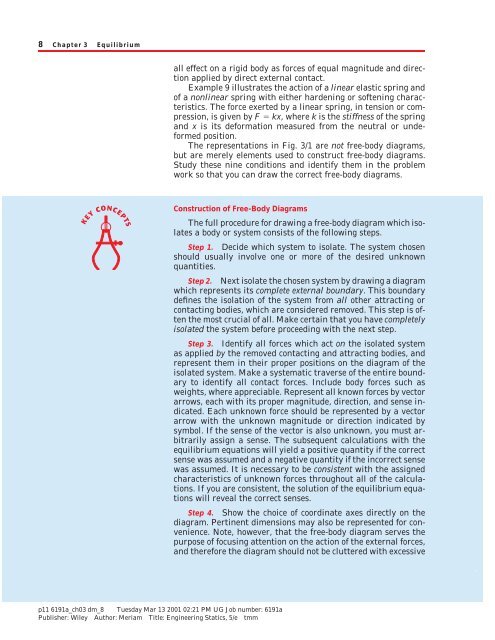
8 Chapter 3 Equilibrium<br />
all effect on a rigid <strong>body</strong> as forces <strong>of</strong> equal magnitude and direction<br />
applied by direct external contact.<br />
Example 9 illustrates the action <strong>of</strong> a l<strong>in</strong>ear elastic spr<strong>in</strong>g and<br />
<strong>of</strong> a nonl<strong>in</strong>ear spr<strong>in</strong>g with either harden<strong>in</strong>g or s<strong>of</strong>ten<strong>in</strong>g characteristics.<br />
The force exerted by a l<strong>in</strong>ear spr<strong>in</strong>g, <strong>in</strong> tension or compression,<br />
is given by F kx, where k is the stiffness <strong>of</strong> the spr<strong>in</strong>g<br />
and x is its de<strong>format</strong>ion measured from the neutral or undeformed<br />
position.<br />
The representations <strong>in</strong> Fig. 3/1 are not <strong>free</strong>-<strong>body</strong> <strong>diagram</strong>s,<br />
but are merely elements used <strong>to</strong> construct <strong>free</strong>-<strong>body</strong> <strong>diagram</strong>s.<br />
Study these n<strong>in</strong>e conditions and identify them <strong>in</strong> the problem<br />
work so that you can draw the correct <strong>free</strong>-<strong>body</strong> <strong>diagram</strong>s.<br />
Construction <strong>of</strong> Free-Body Diagrams<br />
The full procedure for draw<strong>in</strong>g a <strong>free</strong>-<strong>body</strong> <strong>diagram</strong> which isolates<br />
a <strong>body</strong> or system consists <strong>of</strong> the follow<strong>in</strong>g steps.<br />
Step 1. Decide which system <strong>to</strong> isolate. The system chosen<br />
should usually <strong>in</strong>volve one or more <strong>of</strong> the desired unknown<br />
quantities.<br />
Step 2. Next isolate the chosen system by draw<strong>in</strong>g a <strong>diagram</strong><br />
which represents its complete external boundary. This boundary<br />
def<strong>in</strong>es the isolation <strong>of</strong> the system from all other attract<strong>in</strong>g or<br />
contact<strong>in</strong>g bodies, which are considered removed. This step is <strong>of</strong>ten<br />
the most crucial <strong>of</strong> all. Make certa<strong>in</strong> that you have completely<br />
isolated the system before proceed<strong>in</strong>g with the next step.<br />
Step 3. Identify all forces which act on the isolated system<br />
as applied by the removed contact<strong>in</strong>g and attract<strong>in</strong>g bodies, and<br />
represent them <strong>in</strong> their proper positions on the <strong>diagram</strong> <strong>of</strong> the<br />
isolated system. Make a systematic traverse <strong>of</strong> the entire boundary<br />
<strong>to</strong> identify all contact forces. Include <strong>body</strong> forces such as<br />
weights, where appreciable. Represent all known forces by vec<strong>to</strong>r<br />
arrows, each with its proper magnitude, direction, and sense <strong>in</strong>dicated.<br />
Each unknown force should be represented by a vec<strong>to</strong>r<br />
arrow with the unknown magnitude or direction <strong>in</strong>dicated by<br />
symbol. If the sense <strong>of</strong> the vec<strong>to</strong>r is also unknown, you must arbitrarily<br />
assign a sense. The subsequent calculations with the<br />
equilibrium equations will yield a positive quantity if the correct<br />
sense was assumed and a negative quantity if the <strong>in</strong>correct sense<br />
was assumed. It is necessary <strong>to</strong> be consistent with the assigned<br />
characteristics <strong>of</strong> unknown forces throughout all <strong>of</strong> the calculations.<br />
If you are consistent, the solution <strong>of</strong> the equilibrium equations<br />
will reveal the correct senses.<br />
Step 4. Show the choice <strong>of</strong> coord<strong>in</strong>ate axes directly on the<br />
<strong>diagram</strong>. Pert<strong>in</strong>ent dimensions may also be represented for convenience.<br />
Note, however, that the <strong>free</strong>-<strong>body</strong> <strong>diagram</strong> serves the<br />
purpose <strong>of</strong> focus<strong>in</strong>g attention on the action <strong>of</strong> the external forces,<br />
and therefore the <strong>diagram</strong> should not be cluttered with excessive<br />
p11 6191a_ch03 dm_8 Tuesday Mar 13 2001 02:21 PM UG Job number: 6191a<br />
Publisher: <strong>Wiley</strong> Author: Meriam Title: Eng<strong>in</strong>eer<strong>in</strong>g Statics, 5/e tmm
Article 3/2 System Isolation and the Free-Body Diagram 9<br />
extraneous <strong>in</strong><strong>format</strong>ion. Clearly dist<strong>in</strong>guish force arrows from arrows<br />
represent<strong>in</strong>g quantities other than forces. For this purpose<br />
a colored pencil may be used.<br />
Completion <strong>of</strong> the forego<strong>in</strong>g four steps will produce a correct<br />
<strong>free</strong>-<strong>body</strong> <strong>diagram</strong> <strong>to</strong> use <strong>in</strong> apply<strong>in</strong>g the govern<strong>in</strong>g equations,<br />
both <strong>in</strong> statics and <strong>in</strong> dynamics. Be careful not <strong>to</strong> omit from the<br />
<strong>free</strong>-<strong>body</strong> <strong>diagram</strong> certa<strong>in</strong> forces which may not appear at first<br />
glance <strong>to</strong> be needed <strong>in</strong> the calculations. It is only through complete<br />
isolation and a systematic representation <strong>of</strong> all external forces<br />
that a reliable account<strong>in</strong>g <strong>of</strong> the effects <strong>of</strong> all applied and reactive<br />
forces can be made. Very <strong>of</strong>ten a force which at first glance may<br />
not appear <strong>to</strong> <strong>in</strong>fluence a desired result does <strong>in</strong>deed have an <strong>in</strong>fluence.<br />
Thus, the only safe procedure is <strong>to</strong> <strong>in</strong>clude on the <strong>free</strong><strong>body</strong><br />
<strong>diagram</strong> all forces whose magnitudes are not obviously<br />
negligible.<br />
The <strong>free</strong>-<strong>body</strong> method is extremely important <strong>in</strong> mechanics<br />
because it ensures an accurate def<strong>in</strong>ition <strong>of</strong> a mechanical system<br />
and focuses attention on the exact mean<strong>in</strong>g and application <strong>of</strong> the<br />
force laws <strong>of</strong> statics and dynamics. Review the forego<strong>in</strong>g four<br />
steps for construct<strong>in</strong>g a <strong>free</strong>-<strong>body</strong> <strong>diagram</strong> while study<strong>in</strong>g the<br />
<strong>sample</strong> <strong>free</strong>-<strong>body</strong> <strong>diagram</strong>s shown <strong>in</strong> Fig. 3/2 and the Sample<br />
Problems which appear at the end <strong>of</strong> the next article.<br />
Examples <strong>of</strong> Free-Body Diagrams<br />
Figure 3/2 gives four examples <strong>of</strong> mechanisms and structures<br />
<strong>to</strong>gether with their correct <strong>free</strong>-<strong>body</strong> <strong>diagram</strong>s. Dimensions and<br />
magnitudes are omitted for clarity. In each case we treat the entire<br />
system as a s<strong>in</strong>gle <strong>body</strong>, so that the <strong>in</strong>ternal forces are not<br />
shown. The characteristics <strong>of</strong> the various types <strong>of</strong> contact forces<br />
illustrated <strong>in</strong> Fig. 3/1 are used <strong>in</strong> the four examples as they apply.<br />
In Example 1 the truss is composed <strong>of</strong> structural elements<br />
which, taken all <strong>to</strong>gether, constitute a rigid framework. Thus, we<br />
may remove the entire truss from its support<strong>in</strong>g foundation and<br />
treat it as a s<strong>in</strong>gle rigid <strong>body</strong>. In addition <strong>to</strong> the applied external<br />
load P, the <strong>free</strong>-<strong>body</strong> <strong>diagram</strong> must <strong>in</strong>clude the reactions on the<br />
truss at A and B. The rocker at B can support a vertical force<br />
only, and this force is transmitted <strong>to</strong> the structure at B (Example<br />
4 <strong>of</strong> Fig. 3/1). The p<strong>in</strong> connection at A (Example 6 <strong>of</strong> Fig. 3/1) is<br />
capable <strong>of</strong> supply<strong>in</strong>g both a horizontal and a vertical force component<br />
<strong>to</strong> the truss. If the <strong>to</strong>tal weight <strong>of</strong> the truss members is<br />
appreciable compared with P and the forces at A and B, then the<br />
weights <strong>of</strong> the members must be <strong>in</strong>cluded on the <strong>free</strong>-<strong>body</strong> <strong>diagram</strong><br />
as external forces.<br />
In this relatively simple example it is clear that the vertical<br />
component A y must be directed down <strong>to</strong> prevent the truss from<br />
rotat<strong>in</strong>g clockwise about B. Also, the horizontal component A x<br />
will be <strong>to</strong> the left <strong>to</strong> keep the truss from mov<strong>in</strong>g <strong>to</strong> the right under<br />
the <strong>in</strong>fluence <strong>of</strong> the horizontal component <strong>of</strong> P. Thus,<strong>in</strong>con-<br />
p11 6191a_ch03 dm_9 Tuesday Mar 13 2001 02:21 PM UG Job number: 6191a<br />
Publisher: <strong>Wiley</strong> Author: Meriam Title: Eng<strong>in</strong>eer<strong>in</strong>g Statics, 5/e tmm
10 Chapter 3 Equilibrium<br />
SAMPLE FREE–BODY DIAGRAMS<br />
Mechanical System<br />
Free–Body Diagram <strong>of</strong> Isolated Body<br />
1. Plane truss<br />
Weight <strong>of</strong> truss<br />
assumed negligible<br />
compared with P<br />
P<br />
y<br />
P<br />
A<br />
B<br />
A x<br />
x<br />
A y B y<br />
2. Cantilever beam<br />
V<br />
F 3 F 2 F 1 F 3 F 2 F 1<br />
3. Beam<br />
A<br />
Mass m<br />
F<br />
M<br />
W = mg<br />
y<br />
x<br />
Smooth surface<br />
contact at A.<br />
Mass m<br />
P<br />
B<br />
A<br />
M<br />
P<br />
B y<br />
B x<br />
N<br />
W = mg<br />
y<br />
M<br />
x<br />
4. Rigid system <strong>of</strong> <strong>in</strong>terconnected bodies<br />
analyzed as a s<strong>in</strong>gle unit<br />
y<br />
P<br />
Weight <strong>of</strong> mechanism<br />
neglected<br />
P<br />
x<br />
A<br />
B<br />
m<br />
B x<br />
W = mg<br />
A y<br />
B y<br />
Figure 3/2<br />
struct<strong>in</strong>g the <strong>free</strong>-<strong>body</strong> <strong>diagram</strong> for this simple truss, we can easily<br />
perceive the correct sense <strong>of</strong> each <strong>of</strong> the components <strong>of</strong> force<br />
exerted on the truss by the foundation at A and can, therefore,<br />
represent its correct physical sense on the <strong>diagram</strong>. When the<br />
correct physical sense <strong>of</strong> a force or its component is not easily<br />
recognized by direct observation, it must be assigned arbitrarily,<br />
and the correctness <strong>of</strong> or error <strong>in</strong> the assignment is determ<strong>in</strong>ed<br />
by the algebraic sign <strong>of</strong> its calculated value.<br />
In Example 2 the cantilever beam is secured <strong>to</strong> the wall and<br />
subjected <strong>to</strong> three applied loads. When we isolate that part <strong>of</strong> the<br />
beam <strong>to</strong> the right <strong>of</strong> the section at A, we must <strong>in</strong>clude the reactive<br />
forces applied <strong>to</strong> the beam by the wall. The resultants <strong>of</strong> these<br />
reactive forces are shown act<strong>in</strong>g on the section <strong>of</strong> the beam (Ex-<br />
p11 6191a_ch03 dm_10 Tuesday Mar 13 2001 02:21 PM UG Job number: 6191a<br />
Publisher: <strong>Wiley</strong> Author: Meriam Title: Eng<strong>in</strong>eer<strong>in</strong>g Statics, 5/e tmm
Article 3/2 System Isolation and the Free-Body Diagram 11<br />
ample 7 <strong>of</strong> Fig. 3/1). A vertical force V <strong>to</strong> counteract the excess <strong>of</strong><br />
downward applied force is shown, and a tension F <strong>to</strong> balance the<br />
excess <strong>of</strong> applied force <strong>to</strong> the right must also be <strong>in</strong>cluded. Then,<br />
<strong>to</strong> prevent the beam from rotat<strong>in</strong>g about A, a counterclockwise<br />
couple M is also required. The weight mg <strong>of</strong> the beam must be<br />
represented through the mass center (Example 8 <strong>of</strong> Fig. 3/1).<br />
In the <strong>free</strong>-<strong>body</strong> <strong>diagram</strong> <strong>of</strong> Example 2, we have represented<br />
the somewhat complex system <strong>of</strong> forces which actually act on the<br />
cut section <strong>of</strong> the beam by the equivalent force–couple system <strong>in</strong><br />
which the force is broken down <strong>in</strong><strong>to</strong> its vertical component V<br />
(shear force) and its horizontal component F (tensile force). The<br />
couple M is the bend<strong>in</strong>g moment <strong>in</strong> the beam. The <strong>free</strong>-<strong>body</strong> <strong>diagram</strong><br />
is now complete and shows the beam <strong>in</strong> equilibrium under<br />
the action <strong>of</strong> six forces and one couple.<br />
In Example 3 the weight W mg is shown act<strong>in</strong>g through the<br />
center <strong>of</strong> mass <strong>of</strong> the beam, whose location is assumed known<br />
(Example 8 <strong>of</strong> Fig. 3/1). The force exerted by the corner A on the<br />
beam is normal <strong>to</strong> the smooth surface <strong>of</strong> the beam (Example 2 <strong>of</strong><br />
Fig. 3/1). To perceive this action more clearly, visualize an enlargement<br />
<strong>of</strong> the contact po<strong>in</strong>t A, which would appear somewhat<br />
rounded, and consider the force exerted by this rounded corner<br />
on the straight surface <strong>of</strong> the beam, which is assumed <strong>to</strong> be<br />
smooth. If the contact<strong>in</strong>g surfaces at the corner were not smooth,<br />
a tangential frictional component <strong>of</strong> force could exist. In addition<br />
<strong>to</strong> the applied force P and couple M, there is the p<strong>in</strong> connection<br />
at B, which exerts both an x- and a y-component <strong>of</strong> force on the<br />
beam. The positive senses <strong>of</strong> these components are assigned<br />
arbitrarily.<br />
In Example 4 the <strong>free</strong>-<strong>body</strong> <strong>diagram</strong> <strong>of</strong> the entire isolated<br />
mechanism conta<strong>in</strong>s three unknown forces if the loads mg and P<br />
are known. Any one <strong>of</strong> many <strong>in</strong>ternal configurations for secur<strong>in</strong>g<br />
the cable lead<strong>in</strong>g from the mass m would be possible without affect<strong>in</strong>g<br />
the external response <strong>of</strong> the mechanism as a whole, and<br />
this fact is brought out by the <strong>free</strong>-<strong>body</strong> <strong>diagram</strong>. This hypothetical<br />
example is used <strong>to</strong> show that the forces <strong>in</strong>ternal <strong>to</strong> a rigid<br />
assembly <strong>of</strong> members do not <strong>in</strong>fluence the values <strong>of</strong> the external<br />
reactions.<br />
We use the <strong>free</strong>-<strong>body</strong> <strong>diagram</strong> <strong>in</strong> writ<strong>in</strong>g the equilibrium<br />
equations, which are discussed <strong>in</strong> the next article. When these<br />
equations are solved, some <strong>of</strong> the calculated force magnitudes<br />
may be zero. This would <strong>in</strong>dicate that the assumed force does not<br />
exist. In Example 1 <strong>of</strong> Fig. 3/2, any <strong>of</strong> the reactions A x , A y ,orB y<br />
can be zero for specific values <strong>of</strong> the truss geometry and <strong>of</strong> the<br />
magnitude, direction, and sense <strong>of</strong> the applied load P. A zero reaction<br />
force is <strong>of</strong>ten difficult <strong>to</strong> identify by <strong>in</strong>spection, but can be<br />
determ<strong>in</strong>ed by solv<strong>in</strong>g the equilibrium equations.<br />
Similar comments apply <strong>to</strong> calculated force magnitudes<br />
which are negative. Such a result <strong>in</strong>dicates that the actual sense<br />
is the opposite <strong>of</strong> the assumed sense. The assumed positive senses<br />
<strong>of</strong> B x and B y <strong>in</strong> Example 3 and B y <strong>in</strong> Example 4 are shown on the<br />
<strong>free</strong>-<strong>body</strong> <strong>diagram</strong>s. The correctness <strong>of</strong> these assumptions is<br />
p11 6191a_ch03 dm_11 Tuesday Mar 13 2001 02:21 PM UG Job number: 6191a<br />
Publisher: <strong>Wiley</strong> Author: Meriam Title: Eng<strong>in</strong>eer<strong>in</strong>g Statics, 5/e tmm
12 Chapter 3 Equilibrium<br />
proved or disproved accord<strong>in</strong>g <strong>to</strong> whether the algebraic signs <strong>of</strong><br />
the computed forces are plus or m<strong>in</strong>us when the calculations are<br />
carried out <strong>in</strong> an actual problem.<br />
The isolation <strong>of</strong> the mechanical system under consideration<br />
is a crucial step <strong>in</strong> the formulation <strong>of</strong> the mathematical model.<br />
The most important aspect <strong>to</strong> the correct construction <strong>of</strong> the allimportant<br />
<strong>free</strong>-<strong>body</strong> <strong>diagram</strong> is the clear-cut and unambiguous<br />
decision as <strong>to</strong> what is <strong>in</strong>cluded and what is excluded. This decision<br />
becomes unambiguous only when the boundary <strong>of</strong> the <strong>free</strong><strong>body</strong><br />
<strong>diagram</strong> represents a complete traverse <strong>of</strong> the <strong>body</strong> or<br />
system <strong>of</strong> bodies <strong>to</strong> be isolated, start<strong>in</strong>g at some arbitrary po<strong>in</strong>t<br />
on the boundary and return<strong>in</strong>g <strong>to</strong> that same po<strong>in</strong>t. The system<br />
with<strong>in</strong> this closed boundary is the isolated <strong>free</strong> <strong>body</strong>, and all contact<br />
forces and all <strong>body</strong> forces transmitted <strong>to</strong> the system across<br />
the boundary must be accounted for.<br />
The follow<strong>in</strong>g exercises provide practice with draw<strong>in</strong>g <strong>free</strong><strong>body</strong><br />
<strong>diagram</strong>s. This practice is helpful before us<strong>in</strong>g such <strong>diagram</strong>s<br />
<strong>in</strong> the application <strong>of</strong> the pr<strong>in</strong>ciples <strong>of</strong> force equilibrium <strong>in</strong><br />
the next article.<br />
p11 6191a_ch03 dm_12 Tuesday Mar 13 2001 02:21 PM UG Job number: 6191a<br />
Publisher: <strong>Wiley</strong> Author: Meriam Title: Eng<strong>in</strong>eer<strong>in</strong>g Statics, 5/e tmm
Article 3/2 Free-Body Diagram Exercises 13<br />
FREE-BODY DIAGRAM EXERCISES<br />
3/A In each <strong>of</strong> the five follow<strong>in</strong>g examples, the <strong>body</strong> <strong>to</strong> be<br />
isolated is shown <strong>in</strong> the left-hand <strong>diagram</strong>, and an <strong>in</strong>complete<br />
<strong>free</strong>-<strong>body</strong> <strong>diagram</strong> (FBD) <strong>of</strong> the isolated <strong>body</strong><br />
is shown on the right. Add whatever forces are nec-<br />
essary <strong>in</strong> each case <strong>to</strong> form a complete <strong>free</strong>-<strong>body</strong> <strong>diagram</strong>.<br />
The weights <strong>of</strong> the bodies are negligible unless<br />
otherwise <strong>in</strong>dicated. Dimensions and numerical values<br />
are omitted for simplicity.<br />
Body<br />
Incomplete FBD<br />
1. Bell crank<br />
support<strong>in</strong>g mass<br />
m with p<strong>in</strong> support<br />
at A.<br />
Flexible<br />
cable<br />
A<br />
m<br />
T<br />
A<br />
mg<br />
Pull P<br />
P<br />
2. Control lever<br />
apply<strong>in</strong>g <strong>to</strong>rque<br />
<strong>to</strong> shaft at O.<br />
O<br />
F O<br />
3. Boom OA, <strong>of</strong><br />
negligible mass<br />
compared with<br />
mass m. Boom<br />
h<strong>in</strong>ged at O and<br />
supported by<br />
hoist<strong>in</strong>g cable at B.<br />
O<br />
B<br />
A<br />
m<br />
T<br />
O<br />
mg<br />
4. Uniform crate <strong>of</strong><br />
mass m lean<strong>in</strong>g<br />
aga<strong>in</strong>st smooth<br />
vertical wall and<br />
supported on a<br />
rough horizontal<br />
surface.<br />
A<br />
B<br />
A<br />
B<br />
mg<br />
5. Loaded bracket<br />
supported by p<strong>in</strong><br />
connection at A and<br />
fixed p<strong>in</strong> <strong>in</strong> smooth<br />
slot at B.<br />
A<br />
B<br />
Load L<br />
A<br />
B<br />
L<br />
Figure 3/A<br />
p11 6191a_ch03 dm_13 Tuesday Mar 13 2001 02:21 PM UG Job number: 6191a<br />
Publisher: <strong>Wiley</strong> Author: Meriam Title: Eng<strong>in</strong>eer<strong>in</strong>g Statics, 5/e tmm
14 Chapter 3 Equilibrium<br />
3/B In each <strong>of</strong> the five follow<strong>in</strong>g examples, the <strong>body</strong> <strong>to</strong> be<br />
isolated is shown <strong>in</strong> the left-hand <strong>diagram</strong>, and either<br />
a wrong or an <strong>in</strong>complete <strong>free</strong>-<strong>body</strong> <strong>diagram</strong> (FBD) is<br />
shown on the right. Make whatever changes or addi-<br />
tions are necessary <strong>in</strong> each case <strong>to</strong> form a correct and<br />
complete <strong>free</strong>-<strong>body</strong> <strong>diagram</strong>. The weights <strong>of</strong> the bodies<br />
are negligible unless otherwise <strong>in</strong>dicated. Dimensions<br />
and numerical values are omitted for simplicity.<br />
Body<br />
Wrong or Incomplete FBD<br />
1. Lawn roller <strong>of</strong><br />
mass m be<strong>in</strong>g<br />
pushed up<br />
<strong>in</strong>cl<strong>in</strong>e θ.<br />
2. Pry bar lift<strong>in</strong>g<br />
<strong>body</strong> A hav<strong>in</strong>g<br />
smooth horizontal<br />
surface. Bar rests<br />
on horizontal<br />
rough surface.<br />
A<br />
θ<br />
P<br />
P<br />
R<br />
N<br />
mg<br />
N<br />
P<br />
P<br />
3. Uniform pole <strong>of</strong><br />
mass m be<strong>in</strong>g<br />
hoisted <strong>in</strong><strong>to</strong> position<br />
by w<strong>in</strong>ch.<br />
Horizontal support<strong>in</strong>g<br />
surface<br />
notched <strong>to</strong> prevent<br />
slipp<strong>in</strong>g <strong>of</strong> pole.<br />
Notch<br />
T<br />
R<br />
mg<br />
F<br />
4. Support<strong>in</strong>g angle<br />
bracket for frame.<br />
P<strong>in</strong> jo<strong>in</strong>ts<br />
B<br />
B<br />
A<br />
A<br />
F<br />
F<br />
5. Bent rod welded <strong>to</strong><br />
support at A and<br />
subjected <strong>to</strong> two<br />
forces and couple.<br />
A<br />
y<br />
x<br />
P<br />
M<br />
A y<br />
P<br />
M<br />
Figure 3/B<br />
p11 6191a_ch03 dm_14 Tuesday Mar 13 2001 02:21 PM UG Job number: 6191a<br />
Publisher: <strong>Wiley</strong> Author: Meriam Title: Eng<strong>in</strong>eer<strong>in</strong>g Statics, 5/e tmm
Article 3/2 Free-Body Diagram Exercises 15<br />
3/C Draw a complete and correct <strong>free</strong>-<strong>body</strong> <strong>diagram</strong> <strong>of</strong><br />
each <strong>of</strong> the bodies designated <strong>in</strong> the statements. The<br />
weights <strong>of</strong> the bodies are significant only if the mass<br />
is stated. All forces, known and unknown, should be<br />
labeled. (Note: The sense <strong>of</strong> some reaction components<br />
cannot always be determ<strong>in</strong>ed without numerical<br />
calculation.)<br />
1. Uniform horizontal bar <strong>of</strong> mass m<br />
suspended by vertical cable at A and<br />
supported by rough <strong>in</strong>cl<strong>in</strong>ed surface<br />
at B.<br />
5. Uniform grooved wheel <strong>of</strong> mass m<br />
supported by a rough surface and by<br />
action <strong>of</strong> horizontal cable.<br />
A<br />
m<br />
B<br />
m<br />
2. Wheel <strong>of</strong> mass m on verge <strong>of</strong> be<strong>in</strong>g<br />
rolled over curb by pull P.<br />
6. Bar, <strong>in</strong>itially horizontal but deflected<br />
under load L. P<strong>in</strong>ned <strong>to</strong> rigid support<br />
at each end.<br />
P<br />
A<br />
B<br />
L<br />
3. Loaded truss supported by p<strong>in</strong> jo<strong>in</strong>t at<br />
A and by cable at B.<br />
B<br />
7. Uniform heavy plate <strong>of</strong> mass m<br />
supported <strong>in</strong> vertical plane by cable<br />
C and h<strong>in</strong>ge A.<br />
C<br />
A<br />
A<br />
m<br />
L<br />
4. Uniform bar <strong>of</strong> mass m and roller <strong>of</strong><br />
mass m 0 taken <strong>to</strong>gether. Subjected <strong>to</strong><br />
couple M and supported as shown.<br />
Roller is <strong>free</strong> <strong>to</strong> turn.<br />
m M<br />
0<br />
8. Entire frame, pulleys, and contact<strong>in</strong>g<br />
cable <strong>to</strong> be isolated as a s<strong>in</strong>gle unit.<br />
B<br />
m<br />
A<br />
A<br />
L<br />
Figure 3/C<br />
p11 6191a_ch03 dm_15 Tuesday Mar 13 2001 02:21 PM UG Job number: 6191a<br />
Publisher: <strong>Wiley</strong> Author: Meriam Title: Eng<strong>in</strong>eer<strong>in</strong>g Statics, 5/e tmm