Pduino and other Arduino Interfaces for Pd - Artengine
Pduino and other Arduino Interfaces for Pd - Artengine
Pduino and other Arduino Interfaces for Pd - Artengine

You also want an ePaper? Increase the reach of your titles
YUMPU automatically turns print PDFs into web optimized ePapers that Google loves.
<strong><strong>Pd</strong>uino</strong> <strong>and</strong> <strong>other</strong> <strong>Arduino</strong> <strong>Interfaces</strong> <strong>for</strong> <strong>Pd</strong><br />
Marius Schebella<br />
Brooklyn Polytechnic University<br />
333 Jay Street<br />
Brooklyn, NY 11201<br />
marius.schebella@gmail.com<br />
ABSTRACT<br />
In this paper, I will describe the <strong><strong>Pd</strong>uino</strong> interface <strong>and</strong> some<br />
<strong>other</strong> possibilities to connect <strong>Pd</strong> <strong>and</strong> the <strong>Arduino</strong> board <strong>and</strong><br />
show examples of usage in different projects.<br />
<strong>Arduino</strong> is an open-source physical computing input/output<br />
(I/O) device used to develop interactive objects <strong>and</strong> instruments.<br />
<strong><strong>Pd</strong>uino</strong>[15] (written by Hans-Christoph Steiner) is<br />
a <strong>Pd</strong> interface <strong>for</strong> the <strong>Arduino</strong>, consisting of several <strong>Pd</strong> abstractions<br />
<strong>and</strong> the <strong>Arduino</strong> firmware called "Firmata"[9].<br />
Keywords<br />
<strong>Pd</strong>, <strong>Arduino</strong>, <strong><strong>Pd</strong>uino</strong>, Physical Computing, Sensor <strong>Interfaces</strong><br />
1. INTRODUCTION<br />
<strong>Pd</strong> processes data. Data can be received from an outside<br />
source <strong>and</strong> can be sent to an outside source.<br />
Input <strong>and</strong> output data would be sound, video, human interface<br />
data, keyboard comm<strong>and</strong>s, mouse events, joystick<br />
data, MIDI messages, or network communication data. One<br />
class of data is received from <strong>and</strong> sent to the world of physical<br />
computing devices; sensors, electronic units, motors,<br />
robots or instruments. There is no existing st<strong>and</strong>ard <strong>for</strong><br />
the communication between physical computing devices <strong>and</strong><br />
microcontroller interfaces (such as <strong>Arduino</strong>). Additionally<br />
there is no existing st<strong>and</strong>ard <strong>for</strong> communication between microcontroller<br />
interfaces <strong>and</strong> <strong>Pd</strong>. Input <strong>and</strong> output data is determined<br />
by the input <strong>and</strong> output devices the user chooses.<br />
2. PHYSICAL COMPUTING<br />
Sensors are the most common input devices. They sense<br />
<strong>and</strong> measure; linear or spatial position, orientation, movement,<br />
distance, weight, <strong>for</strong>ce, pressure, humidity, temperature,<br />
light intensity, air flow, electrostatic charge <strong>and</strong> much<br />
more. An<strong>other</strong> very common input device would be a switch.<br />
Output devices are all kinds of motors, servos, solenoids,<br />
electric machines, robotic devices, instruments or lights. In-<br />
Permission to make digital or hard copies of all or part of this work <strong>for</strong><br />
personal or classroom use is granted without fee provided that copies are<br />
not made or distributed <strong>for</strong> profit or commercial advantage <strong>and</strong> that copies<br />
bear this notice <strong>and</strong> the full citation on the first page. To copy <strong>other</strong>wise, to<br />
republish, to post on servers or to redistribute to lists, requires prior specific<br />
permission <strong>and</strong>/or a fee.<br />
<strong>Pd</strong> Convention 2007. Montréal, Québec, Canada.<br />
Copyright 2007. Copyright remains with the author(s).<br />
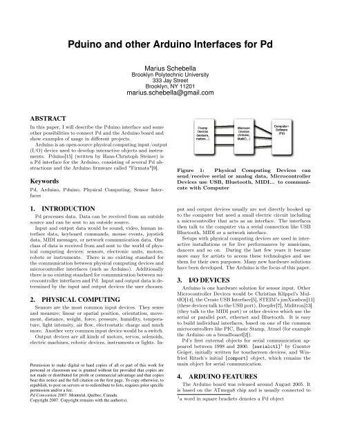
Figure 1: Physical Computing Devices can<br />
send/receive serial or analog data, Microcontroller<br />
Devices use USB, Bluetooth, MIDI... to communicate<br />
with Computer<br />
put <strong>and</strong> output devices usually are not directly hooked up<br />
to the computer but need a small electric circuit including<br />
a microcontroller that acts as an interface. The interfaces<br />
then talk to the computer via a serial connection like USB<br />
Bluetooth, MIDI or a network interface.<br />
Setups with physical computing devices are used in interactive<br />
installations or <strong>for</strong> live per<strong>for</strong>mances by musicians,<br />
dancers <strong>and</strong> so on. During the last few years it became<br />
more easy <strong>for</strong> artists to access these technologies <strong>and</strong> use<br />
them <strong>for</strong> their own purposes. Many new hardware solutions<br />
have been developed. The <strong>Arduino</strong> is the focus of this paper.<br />
3. I/O DEVICES<br />
<strong>Arduino</strong> is one hardware solution <strong>for</strong> sensor input. Other<br />
Microcontroller Devices would be Christian Klippel’s MultIO[14],<br />
the Create USB Interface[5], STEIM’s junXionbox[11]<br />
(these devices talk to the USB port), Doepfer[7], Miditron[13]<br />
(they talk to the MIDI port) or <strong>other</strong> devices which use the<br />
serial or parallel port, ethernet <strong>and</strong> Bluetooth. It is easy<br />
to build individual interfaces, based on one of the common<br />
microcontrollers like PIC, Basic Stamp, Atmel (<strong>for</strong> example<br />
the <strong>Arduino</strong> on a breadboard[2]).<br />
<strong>Pd</strong>’s first external objects <strong>for</strong> serial communication appeared<br />
between 1998 <strong>and</strong> 2000. [serialctl] 1 by Guenter<br />
Geiger, initially written <strong>for</strong> touchscreen devices, <strong>and</strong> Winfried<br />
Ritsch’s initial [comport] object, which remains the<br />
main object <strong>for</strong> serial communication.<br />
4. ARDUINO FEATURES<br />
The <strong>Arduino</strong> board was released around August 2005. It<br />
is based on the ATmega8 chip <strong>and</strong> is usually connected to<br />
1 a word in square brackets denotes a <strong>Pd</strong> object
the computer via USB. It has 13 digital pins, which can<br />
serve both as in <strong>and</strong> outputs, 3 of which allow Pulse-width<br />
modulation (PWM) output, <strong>and</strong> 6 analog inputs. The reference<br />
designs <strong>for</strong> <strong>Arduino</strong> are distributed under a Creative<br />
Commons license Attribution-ShareAlike 2.5.<br />
The <strong>Arduino</strong> soon became widely spread. There is extensive<br />
online documentation with instructions <strong>for</strong> sensors<br />
<strong>and</strong> devices used to measure or control, <strong>and</strong> there is quite<br />
a big internet community (<strong>Arduino</strong> <strong>for</strong>um[1]) where people<br />
can find support. From the very first <strong>Arduino</strong> was used as<br />
a quasi st<strong>and</strong>ard tool <strong>for</strong> teaching "Physical Computing" at<br />
universities or in workshops. Using the <strong>Arduino</strong> programming<br />
language[3] is an easy way to write firmware <strong>for</strong> the<br />
microcontroller. It is an implementation of Wiring, itself<br />
built on Processing.<br />
Of course the <strong>Arduino</strong> board is not the solution <strong>for</strong> everything,<br />
the communication speed of the USB driver is limited<br />
by some technical constrictions (see section 6). The number<br />
of pins is limited (<strong>for</strong> example if you want to build interfaces<br />
with more controllers the MultIO[14] would be a better<br />
choice), but in general <strong>Arduino</strong> is a great learning tool,<br />
easy to use, robust <strong>and</strong> cheap.<br />
Shortly after its release people started to use it in connection<br />
with <strong>Pd</strong>, writing firmware <strong>for</strong> their personal needs, one<br />
of the first examples was presented in Barcelona (2006) by<br />
Alex Posada <strong>and</strong> David Cuartielles.<br />
In early 2006 the first version of <strong><strong>Pd</strong>uino</strong> was released by<br />
Hans-Christoph Steiner.<br />
5. CONNECTING THE ARDUINO TO PD<br />
5.1 USB<br />
There are several possibilities to connect the <strong>Arduino</strong> to<br />
<strong>Pd</strong>. The easiest way is to use the USB port. Here is a very<br />
basic example of <strong>Arduino</strong> code, that will talk to <strong>Pd</strong>.<br />
int switchPin = 2;<br />
// select the input pin <strong>for</strong> the switch<br />
int ledPin = 13;<br />
// select the pin <strong>for</strong> the LED<br />
int switchState = 0;<br />
// value data read from the switch<br />
int ledState = 0;<br />
// variable of the led status<br />
void setup() {<br />
Serial.begin(115200);<br />
// start serial communication to <strong>Pd</strong><br />
}<br />
void loop() {<br />
switchState = digitalRead(switchPin);<br />
// read the state of the switch<br />
Serial.print(switchState, BYTE);<br />
// send the value to the serial port (<strong>Pd</strong>)<br />
if (Serial.available() > 0) {<br />
ledState = Serial.read();<br />
// receive data from <strong>Pd</strong><br />
digitalWrite(ledPin, ledState);<br />
// turn the led on/off<br />
}<br />
}<br />
The code has to be uploaded to the <strong>Arduino</strong> board, using<br />
the <strong>Arduino</strong> IDE.<br />
In <strong>Pd</strong> you create a [comport] object with two arguments:<br />
the number of your device <strong>and</strong> the speed of the connection<br />
[comport 6 115200]. [Fig. 2]<br />
Figure 2: Simple <strong>Pd</strong> connection. Receive data, toggle<br />
the checkbox <strong>and</strong> send the value back<br />
There are two prebuilt systems that you can use, if you<br />
don’t want to write your own microcontroller code. One is<br />
the SMS[18] (Simple Message System) written by Thomas<br />
Ouellet Fredericks <strong>and</strong> the <strong>other</strong> one is <strong><strong>Pd</strong>uino</strong>[15], written<br />
by Hans Christoph Steiner. With both packages, you<br />
still use the <strong>Arduino</strong> Environment to upload the firmware<br />
to the <strong>Arduino</strong>. Both solutions make <strong>Arduino</strong> easily accessible<br />
from within <strong>Pd</strong>. The SMS is an asynchronous serial<br />
communication protocol. <strong>Pd</strong> sends data to the <strong>Arduino</strong> <strong>and</strong><br />
the <strong>Arduino</strong> reacts by returning sensor data.<br />
<strong><strong>Pd</strong>uino</strong> is based on the Firmata firmware, which is trying<br />
to establish a broader st<strong>and</strong>ard of implemention in software<br />
packages as; Processing[16], vvvv[20], Python[17], Max/MSP[12]<br />
or Flash[10]. It uses a compact MIDI like message <strong>for</strong>mat,<br />
optimized <strong>for</strong> high speed data transfer. The <strong>Pd</strong> part of<br />
<strong><strong>Pd</strong>uino</strong> is mainly an object called [arduino] which depends<br />
on some abstractions included in the <strong>Pd</strong>-extended package.<br />
The object reads <strong>and</strong> spits out messages in an easy to h<strong>and</strong>le<br />
message <strong>for</strong>mat.<br />
5.2 Wireless<br />
You don’t necessarily have to connect the <strong>Arduino</strong> via<br />
USB cable. If you have a Bluetooth <strong>Arduino</strong> or a Bluetooth<br />
extension like BlueSmirf or if you want to use a Zigbee[4]<br />
extension <strong>for</strong> wireless data transmission, the device will show<br />
up in the device list of your computer <strong>and</strong> you can directly<br />
use it from within <strong>Pd</strong> using the [comport] object.<br />
5.3 MIDI<br />
It is also possible to assemble the arduino as a MIDI device.<br />
Fig. 3 shows the most simple setup <strong>for</strong> MIDI output[21].<br />
6. SPEED, JITTER AND THE FIRMATA CY-<br />
CLE<br />
The bottle neck of data exchange between <strong>Pd</strong> <strong>and</strong> <strong>Arduino</strong><br />
is within the serial communication (USB cable, bluetooth,<br />
MIDI) <strong>and</strong> the FTDI driver of the microcontroller [8]. The<br />
rule is to encode the in<strong>for</strong>mation in as few bytes as possible<br />
<strong>and</strong> send bytes in packages that fit the driver size of 62 bytes.
sent.) Do this by sending [pinMode pinnumber 1(. After<br />
that you can control the pins by messages like [digital<br />
pinnumber value (. Pins 9-11 also allow pulsewidth modulation<br />
(PWM), a method used to produce analog voltage<br />
output. Send a message [pwm pinnumber value ( (where<br />
value is a float from 0 to 1).<br />
By sending the messages [info( <strong>and</strong> [version( to the<br />
[arduino] object you will receive a message ’version number1<br />
number2 ’, where number1 <strong>and</strong> number2 are the Firmata<br />
version numbers.<br />
Figure 3: MIDI connections; <strong>Arduino</strong> pin 1 is connected<br />
to pin 5 of the MIDI jack, using a 220 Ohm<br />
resistor to connect pin 4 to the power (5V) <strong>and</strong> pin<br />
3 is connected to the ground. MIDI exchanges data<br />
at a baudrate of 31250 bps.<br />
Sensing, encoding <strong>and</strong> decoding takes much less time. This<br />
is more important higher traffic.<br />
The computation on <strong>Arduino</strong> runs in a loop. The first<br />
step is constantly check <strong>for</strong> changing values at the digital<br />
inlets <strong>and</strong> immediately send them to <strong>Pd</strong> without delay. The<br />
second step is executed every 20 milliseconds. During that<br />
call, all data that was received from <strong>Pd</strong> is h<strong>and</strong>led <strong>and</strong> the<br />
analog inputs are read <strong>and</strong> sent to <strong>Pd</strong>. That means messages<br />
from <strong>Pd</strong> to the <strong>Arduino</strong> <strong>and</strong> analog data are processed at a<br />
constant rate of 50 cycles per second. This can cause jitter<br />
of up to 20 milliseconds, but makes sure that even with high<br />
traffic, all data will be sent <strong>and</strong> recieved without delays.<br />
7. PDS ARDUINO OBJECT<br />
Create the [arduino] object with an optional argument,<br />
the device number of your <strong>Arduino</strong>. The message [devices( 2<br />
will give you a list of available devices. You can select an<strong>other</strong><br />
device by sending the message [open devicenumber (<br />
(where devicenumber denotes the number of the corresponding<br />
serial devices).<br />
7.1 Receiving Input<br />
In order to receive data from the <strong>Arduino</strong> you have to<br />
’turn on’ the inlets. Digital inlets are enabled all at once by<br />
the message [digitalIns 1(. Analog inlets are enabled one<br />
by one. For example send the message [analogIns 4 1( to<br />
turn on analog pin 4. Incoming messages are received at the<br />
left outlet of the [arduino] object.The values of the analog<br />
inputs are sent permanently <strong>and</strong> are in a range between<br />
0 <strong>and</strong> 1. For example [analog 4 0.423265( means pin 4<br />
has a current value of 0.423265. Digital inputs will only be<br />
received when they change. The syntax is ’digital pinnumber<br />
value’ (where pinnumber is a single number <strong>and</strong> value one<br />
of 0 or 1).<br />
7.2 Controlling Outputs<br />
To control outputs you first have to switch the corresponding<br />
pin to "output mode". (If the pin was turned on at that<br />
moment, automatically a message "digital pinnumber 0 is<br />
2 words in a square bracket <strong>and</strong> a parenthesis denote a <strong>Pd</strong><br />
message<br />
8. SOME PROJECTS<br />
Here are a few examples of art pieces using <strong>Pd</strong> <strong>and</strong> <strong>Arduino</strong>.<br />
8.1 Barbara’s Radio <strong>and</strong> Barbara’s Kitchen<br />
These are two installations by Diane Ludin <strong>and</strong> Marius<br />
Schebella using <strong>Pd</strong> <strong>and</strong> <strong>Arduino</strong>. The name is chosen after<br />
the American scientist <strong>and</strong> Nobel Prize winner Barbara Mc-<br />
Clintock, who studied chromosomes <strong>and</strong> how they change<br />
during reproduction in maize. The first installation, Barbara’s<br />
Radio plays genome code sequences by using morse<br />
code, which is sent over an electromagnetic field of a solenoid<br />
into a portable FM Radio <strong>and</strong> the <strong>other</strong> installation uses<br />
"kitchen equipment" of a chemical laboratory - test tubes<br />
which are hit by solenoids to produce rhythmical patterns.<br />
8.2 Deflektor <strong>and</strong> Solenoid Concert<br />
"Deflektor"[6] is an installation by Tim Vets <strong>and</strong> Erki De<br />
Vries with rotating panels <strong>and</strong> video projections which was<br />
shown at Z33, Hasselt, Belgium. The projection directions<br />
are controlled by servo-motor-driven mirrors. The rotation<br />
of the panels is also controlled by a <strong>Pd</strong> patch. Everything<br />
runs on a linux system with Puredata, interfacing via 2 <strong>Arduino</strong>’s.<br />
"Solenoid concert"[19] is a piece released on YouTube<br />
showing an installation by Roman Haefeli using solenoids<br />
taped to windows, heating conduit <strong>and</strong> office equipment,<br />
controlled via a <strong>Pd</strong> step sequencer.<br />
9. ACKNOWLEDGMENTS<br />
Miller Puckette (<strong>Pd</strong>), Guenter Geiger (serialctl, <strong>Pd</strong> externals),Winfried<br />
Ritsch (comport, <strong>Pd</strong> externals), Christian<br />
Klippel (MultIO), Hans-Christoph Steiner (Firmata, <strong><strong>Pd</strong>uino</strong>),<br />
Alex Posada (artist), Thomas Ouellet Fredericks (SMS),<br />
Tom Igoe (Author of "Physical Computing"[22], <strong>Arduino</strong><br />
developer), Massimo Banzi (<strong>Arduino</strong> developer), David Cuartielles<br />
(<strong>Arduino</strong> developer), Gianluca Martino (<strong>Arduino</strong> developer),<br />
Dave Mellis (<strong>Arduino</strong> developer), Tim Vets <strong>and</strong><br />
Erki De Vries (artists), Roman Haefeli (artist), Diane Ludin<br />
(artist).<br />
10. REFERENCES<br />
[1] <strong>Arduino</strong> <strong>for</strong>um.<br />
http://www.arduino.cc/cgi-bin/yabb2/YaBB.pl.<br />
[2] <strong>Arduino</strong> on the breadboard. http://itp.nyu.edu/<br />
physcomp/Tutorials/<strong>Arduino</strong>Breadboard.<br />
[3] <strong>Arduino</strong> software.<br />
http://www.arduino.cc/en/Main/Software.<br />
[4] Axic. http://mrtof.danslchamp.org/AXIC.<br />
[5] Cui. http://www.create.ucsb.edu/~dano/CUI.
[6] Deflektor. http://www.timvets.net/projects/<br />
erki<strong>and</strong>tim/deflektor/deflektor.html.<br />
[7] Doepfer. http://www.doepfer.de.<br />
[8] Fast ftdi. http://www.arduino.cc/cgi-bin/yabb2/<br />
YaBB.pl?num=1170939903/11.<br />
[9] Firmata. http://www.arduino.cc/playground/<br />
Interfacing/Firmata.<br />
[10] Flash. http://www.adobe.com/products/flash.<br />
[11] Junxionbox manual. http://www.steim.nl/<br />
software/junxionbox/junXion%20boX%20manual.pdf.<br />
[12] Max/msp. http://www.cycling74.com.<br />
[13] Miditron. http://www.eroktronix.com.<br />
[14] Multio. http://multio.mamalala.de.<br />
[15] <strong><strong>Pd</strong>uino</strong>. http://at.or.at/hans/pd/objects.html.<br />
[16] Processing. http://processing.org.<br />
[17] Python. http://www.python.org.<br />
[18] Sms, simple message system.<br />
http://tof.danslchamp.org.<br />
[19] Solenoid concert.<br />
http://www.youtube.com/watch?v=g_hiz-Kx0kM.<br />
[20] vvvv. http://vvvv.org.<br />
[21] T. Igoe. Midi communication.<br />
http://www.tigoe.net/pcomp/midi.shtml.<br />
[22] D. O’Sullivan <strong>and</strong> T. Igoe. Physical Computing.<br />
Course Technology Ptr, 2004.