preprint - User Interface Research Group - IGARASHI Laboratory
preprint - User Interface Research Group - IGARASHI Laboratory
preprint - User Interface Research Group - IGARASHI Laboratory

You also want an ePaper? Increase the reach of your titles
YUMPU automatically turns print PDFs into web optimized ePapers that Google loves.
Proceedings of the 2010 Conference on New <strong>Interface</strong>s for Musical Expression (NIME 2010), Sydney, Australia<br />
Designing Custom-made Metallophone<br />
with Concurrent Eigenanalysis ∗<br />
Nobuyuki Umetani<br />
The University of Tokyo<br />
JST ERATO<br />
7-3-1 Hongo, Bunkyo-ku,<br />
Tokyo, 113-0033 Japan<br />
umetani@ui.is.s.utokyo.ac.jp<br />
Jun Mitani<br />
University of Tsukuba<br />
JST ERATO<br />
Tsukuba Ibaraki<br />
305-8573 Japan<br />
mitani@cs.tsukuba.ac.jp<br />
Takeo Igarashi<br />
The University of Tokyo<br />
JST ERATO<br />
7-3-1 Hongo, Bunkyo-ku,<br />
Tokyo, 113-0033 Japan<br />
takeo@acm.org<br />
ABSTRACT<br />
We introduce an interactive interface for the custom design<br />
of metallophones. The shape of each plate must be determined<br />
in the design process so that the metallophone will<br />
produce the proper tone when struck with a mallet. Unfortunately,<br />
the relationship between plate shape and tone is<br />
complex, which makes it difficult to design plates with arbitrary<br />
shapes. Our system addresses this problem by running<br />
a concurrent numerical eigenanalysis during interactive geometry<br />
editing. It continuously presents a predicted tone to<br />
the user with both visual and audio feedback, thus making<br />
it possible to design a plate with any desired shape and tone.<br />
We developed this system to demonstrate the effectiveness<br />
of integrating real-time finite element method analysis into<br />
geometric editing to facilitate the design of custom-made<br />
musical instruments. An informal study demonstrated the<br />
ability of technically unsophisticated user to apply the system<br />
to complex metallophone design.<br />
Keywords<br />
Modeling - Modeling <strong>Interface</strong>s, Modeling - Geometric Modeling,<br />
Modeling - CAD, Methods and Applications - Education,<br />
Real-time FEM<br />
1. INTRODUCTION<br />
Each acoustic musical instrument has its own typical shape<br />
and appearance. Although the exterior may show subtle<br />
differences, the fundamental shape cannot be very different<br />
(e.g., metallophone plates are always rectangular).<br />
Although these shapes have become sophisticated through<br />
years of refinement, the appearance of musical instruments<br />
can be repetitive and characterless. Conveying character,<br />
or a message, through appearance is a major challenge for<br />
the makers of acoustic musical instruments. Because the<br />
shapes of acoustic musical instruments and their tones are<br />
inseparable, making designing them much more complex,<br />
∗ The supplemental video can be seen at http://www.<br />
youtube.com/watch?v=7TfMgwuDHS4<br />
Permission to make digital or hard copies of all or part of this work for<br />
personal or classroom use is granted without fee provided that copies are<br />
not made or distributed for profit or commercial advantage and that copies<br />
bear this notice and the full citation on the first page. To copy otherwise, to<br />
republish, to post on servers or to redistribute to lists, requires prior specific<br />
permission and/or a fee.<br />
NIME2010, June 15-18, 2010, Sydney, Australia<br />
Copyright 2010, Copyright remains with the author(s).<br />
acoustic musical instruments cannot have individual designs<br />
like electric guitars.<br />
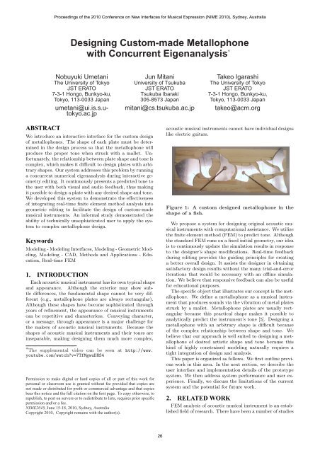
Figure 1: A custom designed metallophone in the<br />
shape of a fish.<br />
We propose a system for designing original acoustic musical<br />
instruments with computational assistance. We utilize<br />
the finite element method (FEM) to predict tone. Although<br />
the standard FEM runs on a fixed initial geometry, our idea<br />
is to continuously update the simulation results in response<br />
to the designer’s shape modifications. Real-time feedback<br />
during editing provides the guiding principles for creating<br />
a better overall design. It assists the designer in obtaining<br />
satisfactory design results without the many trial-and-error<br />
iterations that would be necessary with an offline simulation.<br />
We believe that responsive feedback can also be useful<br />
for educational purposes.<br />
The specific object that illustrates our concept is the metallophone.<br />
We define a metallophone as a musical instrument<br />
that produces sounds via the vibration of metal plates<br />
struck by a mallet. Metallophone plates are usually rectangular<br />
because this practical shape makes it possible to<br />
analytically predict the instrument’s tone [5]. Designing a<br />
metallophone with an arbitrary shape is difficult because<br />
of the complex relationship between shape and tone. We<br />
believe that our approach is well suited to designing a metallophone<br />
of desired artistic shape and tone because this<br />
kind of highly constrained modeling naturally requires a<br />
tight integration of design and analysis.<br />
This paper is organized as follows. We first outline previous<br />
work in this area. In the next section, we describe the<br />
user interface and implementation details of the prototype<br />
system. We then address system performance and user experience.<br />
Finally, we discuss the limitations of the current<br />
system and the potential for future work.<br />
2. RELATED WORK<br />
FEM analysis of acoustic musical instrument is an established<br />
field of research. There have been a number of studies<br />
26
Proceedings of the 2010 Conference on New <strong>Interface</strong>s for Musical Expression (NIME 2010), Sydney, Australia<br />
on the use of FEM eigenanalysis for predicting the tones of<br />
various musical instruments, such as piano [9], guitar [2],<br />
and xylophone [3]. Shoofs et al. [15] used FEM eigenanalysis<br />
to determine the optimal shape of carillon bells. However,<br />
eigenanalysis have previously been used exclusively as<br />
an offline evaluation tool and has not been directly integrated<br />
into geometry editing as in our system<br />
Automatic optimization methods can be used to design<br />
objects that satisfy physical constraints. For example, Smith<br />
et al. [16] applied an optimization approach to the design<br />
of truss structures. However, automatic methods present<br />
many practical difficulties, such as explicitly specifying constraints<br />
and parameter spaces that are too large. The interactive<br />
approach offers the advantage of allowing users<br />
to use their own preferences and judgment during the design<br />
process while considering less tangible factors such as<br />
aesthetics.<br />
Various techniques have been suggested for making physical<br />
simulations interactive. One approach is to use precomputations.<br />
James and Pai [6] performed an interactive<br />
physical simulation of deformable objects by precomputing<br />
the matrices of reference boundary value problems. They<br />
also proposed modal analyses of dynamic elastic models for<br />
real-time deformation simulations [7]. Another approach<br />
is to use approximations for nonlinear elasticity to achieve<br />
large deformations quickly and stably [12]. These methods<br />
require user input as an external force in a continuously<br />
running simulation. In our system, the user directly modifies<br />
the definition of the target problem, and the system<br />
reruns the simulation with the new setting.<br />
Our goal is to aid the design process by using physical<br />
simulations. Our system shares some concepts with firstorder<br />
analysis [13], which emphasizes the importance of using<br />
simulation in the early stages of a design. Masry and<br />
Lipson [10] develop a sketch-based three-dimensional (3D)<br />
modeling interface capable of FEM analysis that has a similar<br />
objective to our own. However, first-order analysis is not<br />
very different from conventional computer-aided design and<br />
computer-aided engineering systems, in that the analysis is<br />
performed after some of the design processes have already<br />
occurred. In contrast, in our own system the analysis is<br />
performed during the design process. Several systems have<br />
been proposed for designing physical objects such as stuffed<br />
animals with the aid of interactive simulations [11]. However,<br />
the focus of those systems is mainly the user interface,<br />
and they involve relatively simple simulation procedures.<br />
3. USER INTERFACE<br />
This section describes our metallophone design system<br />
from the user’s point of view. The system basically operates<br />
as a two-dimensional (2D) modeling program in which the<br />
user interactively edits the shape of a metallophone plate<br />
using direct manipulation (Figure 3). FEM eigenfrequency<br />
analysis runs concurrently with the user manipulation and<br />
presents the predicted tone to the user with visual and audio<br />
feedback. The system also provides 3D graphics of the geometric<br />
deformation of the plate during vibration. In this<br />
way, the user, guided by artistic inspiration, can explore<br />
various plate shapes while continuously verifying that the<br />
desired tone is produced.<br />
Figure 3 shows a set of modeling operations provided by<br />
our system. A metallophone plate is represented as a closed<br />
area surrounded by straight lines and arcs, connected by<br />
corner vertices. The user drags the corner vertices to move<br />
them, and drags the arc to change its radius. The user can<br />
also add and delete corner vertices. Our current implementation<br />
does not support plates with holes. More complex<br />
2D view<br />
(Shape design)<br />
3D view<br />
(Eigenmode)<br />
Scale / frequency<br />
Figure 2: Metallophone design software. The left<br />
window is used for the original 2D design, whereas<br />
the right window shows the analyzed eigenmode as<br />
a 3D graphic. The tone is updated in real time with<br />
both audio and visual feedback for the user.<br />
curves, such as Bézier curves or NURBS, permit the creation<br />
of more diverse shapes; this is left to future development.<br />
add<br />
point<br />
drag<br />
point<br />
drag<br />
arc<br />
Figure 3: The modeling operations of our software:<br />
adding and deleting a point, dragging an arc and a<br />
point.<br />
The system continuously predicts the tone that the plate<br />
will produce when struck with a mallet and presents it to<br />
the user during the editing process. Visual feedback is given<br />
as a numerical value (Figure 2, bottom) and audio feedback<br />
is provided in the form of a sine wave, with the speaker<br />
emitting the predicted tone. As the user drags the corner<br />
vertex, the tone from the speaker and the numerical value<br />
on the screen gradually change. Audio feedback allows the<br />
user to continuously monitor the tone while editing, and<br />
visual feedback is useful for verifying the exact value. Low<br />
tones tend to be produced by large plates (and vice versa),<br />
and the user can observe and learn this phenomenon during<br />
interactive editing, which facilitates the overall design<br />
process.<br />
The system also predicts the geometric deformation of<br />
the plate during vibration and visually presents it to the<br />
user as a 3D graphic (Figure 2, right). The actual deformation<br />
is too small to be visible, so the system exaggerates<br />
it in the visualization. This helps the user decide where<br />
the plate should be attached to the base, because the plate<br />
should be attached at a point of minimal deformation. It is<br />
also useful for visually evaluating the quality of the vibrations.<br />
Vibrations perpendicular to the plate are desirable<br />
because they are excited when the mallet strikes the face<br />
vertically, whereas a plane vibration is not likely to occur<br />
during a performance, and its tone is not dominant (Figure<br />
4). Thus, the user should strive for a shape that produces<br />
perpendicular vibrations.<br />
The system only supports the design of individual plate<br />
geometry, and physical construction must be done manually<br />
(Figure 5). The user may export the plate geometry to a<br />
DXF file and then send it to a wire-electrical discharge machine<br />
for the actual cutting of the metal plate. The metal<br />
plate can also be cut manually with a band saw. Some<br />
errors always occur during this process, and the finished<br />
27
Proceedings of the 2010 Conference on New <strong>Interface</strong>s for Musical Expression (NIME 2010), Sydney, Australia<br />
Good<br />
Bad<br />
simple to implement and yield sufficiently accurate results.<br />
The use of thick plate elements will be a subject of future<br />
research.<br />
2 layers of tetrahedral elements<br />
Figure 4: Perpendicular vibration mode is desirable<br />
(left), whereas in plane vibration mode is undesirable<br />
(right)<br />
metal plate will not produce exactly the same tone as the<br />
simulated plate. It is therefore necessary to adjust the tone<br />
by rasping the plate. Our system is also useful in this regard,<br />
because it is able to predict how the tone will change<br />
when particular edges are rasped. Finally, the user attaches<br />
the plate to a wooden board at the point suggested by the<br />
vibration shape analysis.<br />
Design<br />
spectrum analyzer<br />
Adjust<br />
150mm<br />
4mm<br />
Actual<br />
creation<br />
Figure 6: The mesh used in FEM discretization. We<br />
use double-layered tetrahedral elements extruded<br />
from a triangular 2D mesh.<br />
4.2 Mesh Deformation<br />
To continuously simulate a tone during a user’s shape<br />
editing, the system adjusts the mesh to fit the shape. To<br />
adjust the mesh to fit a user-specified shape, the system<br />
first places the nodes on the boundary and then applies<br />
smoothing to the nodes inside the boundary. We use Laplacian<br />
smoothing if the mesh distortion is small (Figure 7).<br />
When the change in the boundary is large and the mesh is<br />
distorted, we employ Delaunay smoothing to suppress the<br />
mesh distortion.<br />
Cut<br />
band saw<br />
Arrange & Fix<br />
Figure 5: The process of producing a metallophone:<br />
first, cutting the metal plate; second, adjusting the<br />
tone by rasping; finally, attaching the plate to a<br />
wooden board.<br />
4. IMPLEMENTATION<br />
4.1 FEM model for eigenmode analysis<br />
In our current implementation, a metallophone plate is<br />
modeled as a thin 3D linear solid plate extruded from a 2D<br />
shape designed by the user. We discretize the solid into<br />
tetrahedral elements by first triangulating the 2D shape,<br />
then extruding each triangle to obtain a 3D prism, and finally<br />
dividing each prism into tetrahedra. We then apply<br />
FEM eigenvalue analysis to compute its tone, or eigenfrequency.<br />
The deformation caused by the vibration is computed<br />
as the eigenmode corresponding to the eigenvalue.<br />
Note that the simulation parameters must be calibrated for<br />
each specific material. We use aluminum plate with a thickness<br />
of 4mm. The simulation accuracy is very sensitive to<br />
the mesh density, because we use linear tetrahedral elements<br />
to represent a bend in a 3D plate. To alleviate this problem,<br />
known as “shear-locking” [17], we must prevent excessive<br />
distortions of the tetrahedral elements. We divide the plate<br />
into two layers, each filled with tetrahedral elements (Figure<br />
6), such that the longest edge is always shorter than<br />
two times the shortest edge. Thick plate elements might<br />
work very well here in place of tetrahedral elements, but we<br />
have chosen to use tetrahedral elements because they are<br />
Figure 7: The smoothing of mesh using Laplacian<br />
smoothing<br />
4.3 Eigenmode analysis of the metallophones<br />
We assume that the metallophone is floating in a gravityfree<br />
space without any external forces or fixed boundaries<br />
(which makes the stiffness matrix singular). Generalized<br />
eigenanalysis with a singular stiffness matrix has been investigated<br />
in the field of aerospace engineering [4, 8]. A typical<br />
method of obtaining an eigenvalue and its eigenmode<br />
consists of first shifting the stiffness matrix with the mass<br />
matrix, then calculating the distribution of the eigenvalues<br />
using the Lanczos or Jacobi method to obtain the lowest<br />
nonzero eigenvalue, and finally calculating the eigenmode<br />
by shifted inverse iteration [14]. However, the extensive<br />
calculation of the distribution of all of the eigenvalues is<br />
unnecessary for our purpose. Hence, we compute only the<br />
smallest nonzero eigenvalue, which enables real-time performance.<br />
We also take advantage of the problem setting.<br />
First, we already know that the kernel of the coefficient matrix<br />
consists of translations and rotations. Second, we can<br />
reuse the solution from the previous configuration as a good<br />
initial guess for the inverse iteration.<br />
Here is a detailed derivation of the algorithm we use. The<br />
eigenvalue problem is formulated using the FEM discretization<br />
as<br />
¯Mü + Ku = 0 (1)<br />
where u is the nodal displacement vector, ¯M is the lumped<br />
mass matrix, and K is the positive semi-definite stiffness<br />
28
Proceedings of the 2010 Conference on New <strong>Interface</strong>s for Musical Expression (NIME 2010), Sydney, Australia<br />
matrix. By splitting the displacement u into the product of<br />
a spatially varying amplitude φ and a harmonic oscillation<br />
with angular velocity ω, u(x, t) = φ(x)e iωt , and substituting<br />
this into Eq.(1), we obtain<br />
Kφ = λ ¯Mφ (2)<br />
where the eigenfrequency f = ω/(2π) = √ λ/(2π). Our<br />
goal is to calculate the smallest nonzero eigenvalue λ and<br />
its corresponding eigenvector φ.<br />
Cholesky factorization is employed to represent the lumped<br />
mass matrix as ¯M = LL T , and both sides of Eq.(2) are multiplied<br />
on the left by L −1 to obtain the standard eigenvalue<br />
problem<br />
Aψ = λψ (3)<br />
where A = L −1 KL −T and ψ = L T φ. We solve this by<br />
inverse iteration. The standard iteration procedure is modified<br />
by adding a step that removes all zero eigenvectors of<br />
A from the current solution. Because of our problem setting,<br />
we already know that the zero eigenvectors of K are<br />
φ i 0 (i = 1 . . . 6), the translations along the three coordinate<br />
axes and the rotations around them. We then apply modified<br />
Gram-Schmidt orthogonalization to L T φ i 0 (i = 1 . . . 6)<br />
to obtain the orthonormal basis vectors ψ i 0 (i = 1 . . . 6)<br />
that span the kernel of A, and define a projection P that<br />
maps a vector v to the complement space of the kernel of<br />
A by P(v) = v − ∑ (<br />
ψ i 0 ψ<br />
i<br />
0 · v) . In each step of the iteration,<br />
we apply this projection to the solution vector and<br />
normalize it. We add a small positive number ε to the diagonals<br />
of A to improve the numerical conditions. Once the<br />
shifted eigenvalue λ ′ 1 and its corresponding eigenvector ψ 1<br />
of A are computed, we finally obtain the smallest nonzero<br />
eigenvalue λ 1 = λ ′ 1 − ε and the eigenvector φ 1 = L −T ψ 1 .<br />
Reusing of the solution from the previous configuration significantly<br />
improves the convergence of the inverse iterations.<br />
The processing returns to the main thread in each iteration<br />
step to avoid freezing to user input.<br />
5. RESULTS<br />
5.1 System Performance<br />
Table 1 summearizes the performance of our system. Because<br />
the performance depends on user operations, we measured<br />
the average number of frames per second during the<br />
continuous editing of shapes. In our current implementation,<br />
the number of elements is proportional to the area of<br />
the plate, because we have limited the edge length to avoid<br />
element distortions, as described in Section 4. This causes<br />
a slight slowdown when the shape is large, but we consider<br />
it acceptable.<br />
Size (mm) #Tetrahedra FPS Frequency (Hz)<br />
100 × 30 2196 10.7 1931<br />
150 × 30 3192 4.2 860<br />
200 × 30 4524 3.3 494<br />
Table 1: The performance of our system during interactive<br />
mnipulation, tested with a 2.5GHz CPU<br />
and 2.0GB RAM. The first column shows the size<br />
of the rectangular metallophone plates, the second<br />
shows the number of tetrahedral elements, the third<br />
shows the frame per second, the fourth shows the<br />
frequencies (Hz).<br />
5.2 <strong>User</strong> Experience<br />
We asked a professional artist to design a metallophone<br />
using our software. The artist was allowed to work on<br />
the task freely and without time limitations and was provided<br />
instructions when required. We then used an electoric<br />
discharge machine to manufacture an actual metallophone<br />
based on the artist’s design. Figure 8 shows the shapes<br />
designed to correspond to the musical scale notes from C<br />
(523 Hz) to B (987 Hz). After the design of each piaces, we<br />
trimed and assembled the metallophone (Figure 1)<br />
F<br />
Designed<br />
shape<br />
Analyzed<br />
eigenmode<br />
C D E<br />
G<br />
Figure 8: Metallophone shapes designed by an<br />
artist. The upper row shows the designed 2D<br />
shapes, whereas the lower row shows their analyzed<br />
eigenmodes in 3D.<br />
The top three rows in Table 2 show that the frequencies<br />
of most of the pieces conformed well to one another for the<br />
target, the simulation, and the actual metallophone. To further<br />
improve the quality, we manually adjusted the tones<br />
of the actual metallophone pieces by trimming their edges<br />
(except for the piece corresponding to F). As mentioned in<br />
Section 3, our metallophone design software was also useful<br />
for this adjustment process, because it was able to predict<br />
the tone changes caused by edge trimming. The bottom row<br />
in Table 2 lists the frequencies of the actual metallophone<br />
after manual adjustment. Although inharmonic overtones<br />
make the timbre unclear, we found that the sounds produced<br />
by an actual metallophone were of acceptable quality<br />
for a hobbyist.<br />
Scale C D E F G A B<br />
Targeted 523 587 659 698 783 880 987<br />
Simulated 525 588 661 699 786 880 989<br />
Measured 506 604 621 698 787 860 993<br />
Adjusted 523 587 659 698 783 881 987<br />
Table 2: Target, simulated, measured, and adjusted<br />
frequencies (Hz) of the metallophone for each note<br />
in the scale, illustrating the accuracy of our analysis.<br />
We interviewed the artist afterward to obtain subjective<br />
feedback. The artist reported that the design took roughly<br />
5 hours to complete, with most of the time being devoted<br />
to the C and D pieces. This was mainly because these lower<br />
tones required larger areas than the others, which greatly<br />
slowed the response of the analysis. One of the difficulties<br />
the artist encountered during the design process was<br />
needing to maintain an overall balance in shape among the<br />
pieces while keeping their tones true to the intended tone.<br />
This was a major design constraint. Another difficulty was<br />
that sometimes a small modification of the shape resulted<br />
in a large change tone, necessitating high responsiveness<br />
of the analysis. Finally, the artist noted that the relationship<br />
between the shape and tone of the metallophone was<br />
still difficult to understand, even after participating in this<br />
study. Nevertheless, the artist at least learned that larger<br />
A<br />
B<br />
29
Proceedings of the 2010 Conference on New <strong>Interface</strong>s for Musical Expression (NIME 2010), Sydney, Australia<br />
pieces tend to produce lower tones, having previously believed<br />
the opposite to be true.<br />
6. LIMITATIONS AND FUTURE WORK<br />
Our current system only computes the smallest nonzero<br />
eigenvalue and its eigenmode. This is sufficient for predicting<br />
the basic tone, but the computing higher order eigenvalues<br />
and eigenmodes is necessary to more accurately predict<br />
the resulting timbre. We plan to address this problem in<br />
the future. Another interesting possibility is to design a special<br />
metallophone plate that produces different tones when<br />
struck with a mallet in different positions.<br />
The present implementation uses volumetric tetrahedral<br />
elements to model the metallophone plate. However, modeling<br />
with locking-free thick plate elements [1] might be more<br />
efficient for this purpose. The simulation for an overtone is<br />
computationally more demanding, and thick plate elements<br />
might be necessary in this case. One advantage of volumetric<br />
elements is that they are able to support truly 3D form<br />
factors, such as those in a sculpture; this is another possible<br />
direction for future research.<br />
Interactive eigenanalysis could potentially be extended to<br />
the design of other musical instruments. We are planning<br />
to develop a system for designing a wind instrument, such<br />
as an ocarina. In this case, we would need to perform eigenanalysis<br />
on a sound wave equation. Finally, we believe that<br />
interactive shape design with concurrent FEM analysis will<br />
be useful for more general design problems, and we plan to<br />
test it in other domains.<br />
7. ACKNOWLEDGMENTS<br />
This project was partially supported by 2008 IPA Exploratory<br />
Software Project (Project Manager: Ikuo Takeuchi),<br />
Information-Technology Promotion Agency, Japan. We would<br />
like to thank Yuki Tsujita for designing the fish shaped metallophone,<br />
Greg Saul for his help in the construction of the<br />
metallophone, JST ERATO project members for valuable<br />
suggestions and help, and anonymous reviewers for their<br />
constructive feedback.<br />
[7] D. L. James and D. K. Pai. Dyrt: dynamic response<br />
textures for real time deformation simulation with<br />
graphics hardware. ACM Trans. Graph.,<br />
21(3):582–585, 2002.<br />
[8] A. Jennings. Natural Vibrations of a Free Structure.<br />
Aircraft Engng, 34:81–83, 1962.<br />
[9] J. Kindel and I. Wang. Vibrations of a piano<br />
soundboard: Modal analysis and finite element<br />
analysis. The Journal of the Acoustical Society of<br />
America, 81:S61, 1987.<br />
[10] M. Masry and H. Lipson. A sketch-based interface for<br />
iterative design and analysis of 3d objects. In<br />
Proceedings of Eurographics workshop on<br />
Sketch-Based <strong>Interface</strong>s, pages 109–118, Dublin,<br />
Ireland, Aug 2005.<br />
[11] Y. Mori and T. Igarashi. Plushie: an interactive<br />
design system for plush toys. ACM Trans. Graph.,<br />
26(3):45, 2007.<br />
[12] M. Müller, J. Dorsey, L. McMillan, R. Jagnow, and<br />
B. Cutler. Stable real-time deformations. In<br />
Proceedings of the 2002 ACM<br />
SIGGRAPH/Eurographics symposium on Computer<br />
animation, pages 49–54, 2002.<br />
[13] H. Nishigaki, S. Nishiwaki, T. Amago, and<br />
N. Kikuchi. First order analysis for automotive body<br />
structure design. In ASME DETC, 2000.<br />
[14] Y. Saad. Numerical Methods for Large Eigenvalue<br />
Problems (Algorithms and Architectures for Advanced<br />
Scientific Computing). Manchester Univ Pr, 4 1995.<br />
[15] A. Schoofs, F. Van Asperen, P. Maas, and A. Lehr. A<br />
Carillon of Major-Third Bells. I. Computation of Bell<br />
Profiles using Structural Optimization. Music<br />
Perception, 4(3):255–266, 1987.<br />
[16] J. Smith, J. Hodgins, I. Oppenheim, and A. Witkin.<br />
Creating models of truss structures with optimization.<br />
ACM Trans. Graph., 21(3):295–301, 2002.<br />
[17] O. Zienkiewicz, R. Taylor, and J. Zhu. The finite<br />
element method: its basis and fundamentals.<br />
Butterworth-Heinemann, 2005.<br />
8. ADDITIONAL AUTHORS<br />
Kenshi Takayama (The University of Tokyo, JST ER-<br />
ATO, email: kenshi@ui.is.s.tokyo.ac.jp)<br />
9. REFERENCES<br />
[1] K. Bathe and E. Dvorkin. A formulation of general<br />
shell elements- the use of mixed interpolation of<br />
tensorial components. International Journal for<br />
Numerical Methods in Engineering, 22:697–722, 1986.<br />
[2] E. Bécache, A. Chaigne, G. Derveaux, and P. Joly.<br />
Numerical simulation of a guitar. Computers and<br />
Structures, 83(2-3):107–126, 2005.<br />
[3] J. Bretos and C. Santamara. Finite element analysis<br />
and experimental measurements of natural<br />
eigenmodes and random responses of wooden bars<br />
used in musical instruments. Applied Acoustics,<br />
56(3):141–156, 1999.<br />
[4] H. Cox. Vibration of missiles: Matric formulation of<br />
the problem involving free and harmonically forced<br />
flexural vibrations. Aircraft Engineering and<br />
Aerospace Technology, 33, 1961.<br />
[5] N. H. Fletcher and T. D. Rossing. The physics of<br />
musical instruments. 6 1998.<br />
[6] D. L. James and D. K. Pai. Artdefo: accurate real<br />
time deformable objects. In Proceedings of<br />
SIGGRAPH ’99, pages 65–72, 1999.<br />
30