TEST SIGNALS for Setting up Subwoofer-based Systems - Neumann
TEST SIGNALS for Setting up Subwoofer-based Systems - Neumann
TEST SIGNALS for Setting up Subwoofer-based Systems - Neumann

Create successful ePaper yourself
Turn your PDF publications into a flip-book with our unique Google optimized e-Paper software.
<strong>TEST</strong> <strong>SIGNALS</strong> <strong>for</strong> <strong>Setting</strong> <strong>up</strong> <strong>Subwoofer</strong>-<strong>based</strong> <strong>Systems</strong><br />
georg neumann gmbh · ollenhauerstr. 98 · 13403 berlin · germany<br />
tel +49 (0)30 /41 77 24-0 · fax -50 · headoffice@neumann.com · www.neumann.com
1. Introduction<br />
<strong>Neumann</strong> loudspeakers will give their best acoustical per<strong>for</strong>mance when they have been set <strong>up</strong> correctly. The<br />
per<strong>for</strong>mance of a loudspeaker changes when it is placed into an acoustical space. Some of these changes can be<br />
corrected using the acoustical controls built into the loudspeaker. Some of the changes cannot be equalized and require<br />
a change of location or some <strong>for</strong>m of acoustical treatment added to the room.<br />
To help set <strong>up</strong> the loudspeakers some (.mp3 <strong>for</strong>matted) audio test signals have been prepared. The test signals and<br />
their appropriate use are described and each test signal can be downloaded by clicking on the link.<br />
Some of the test procedures described below require two people: one to adjust the controls on the subwoofer and the<br />
other sitting in the listening position.<br />
2. Positioning the Loudspeaker and <strong>Subwoofer</strong> Cabinets in the Room<br />
Be<strong>for</strong>e setting the relative levels and phase of the loudspeakers and subwoofers, correctly position them within the<br />
room and then adjust the equalizer controls to compensate <strong>for</strong> that positioning. The acoustical controls of the<br />
loudspeakers should be set according to their instruction manuals.<br />
Positioning the loudspeakers and subwoofers<br />
<strong>Subwoofer</strong>s are typically positioned close to a wall (
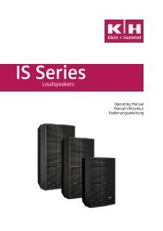
Frequency Response<br />
dB<br />
Bass Managed System<br />
0<br />
-10<br />
-20<br />
-30<br />
10 50 100 500 1k 5k 10k 20k Hz<br />
It is important that the loudspeakers are correctly positioned be<strong>for</strong>e setting the level and phase controls on the<br />
subwoofer, as any later change in position will require the level and phase to be readjusted.<br />
<strong>Setting</strong> the subwoofer’s acoustical controls<br />
The in-room response of the subwoofer can be checked using the range of test tone tracks from 15 to 90 Hz:<br />
• While sitting in the listening position, start at 90 Hz and gradually decrease the frequency, listening carefully <strong>for</strong><br />
any changes in the sound level. It is likely that there will be peaks at certain frequencies, caused by constructive<br />
interference or strong resonances.<br />
• Increases in level below 35 Hz can be corrected using the Low Cut control. Adjust it so that this very low region<br />
sounds to be at the same level as the rest of the response.<br />
• For increases in level above 35 Hz, play a tone at the problem frequency, and switch the parametric equalizer on.<br />
Set the Q to its maximum value, 8, and the gain to its minimum value, -12dB. Adjust the frequency control to focus<br />
on the centre frequency of the peak. Then adjust the Q and the gain in order to give an overall flat sounding<br />
frequency response in this area.<br />
• If there is a decrease in level rather than a peak, the equalizer can be used to increase the offending frequency in<br />
the same way.<br />
3. Pink noise from 60 Hz <strong>up</strong>wards, with a 10 Hz wide cut centered on 80 Hz<br />
This test signal “01 - Pink noise with 80Hz cut.mp3” is used to set the level of a subwoofer relative to the level of a<br />
main loudspeaker. Play the test signal through the loudspeaker/subwoofer combination and repeatedly enable and<br />
disable the subwoofer using the Bass Management control. Adjust the level of the subwoofer until the level of bass<br />
energy does not change whether the subwoofer is disabled or not. Repeat this process <strong>for</strong> each loudspeaker/subwoofer<br />
combination in the system, but this time adjust the level of the loudspeaker not the subwoofer.<br />
<strong>TEST</strong> <strong>SIGNALS</strong> <strong>for</strong> <strong>Setting</strong> <strong>up</strong> <strong>Subwoofer</strong>-<strong>based</strong> <strong>Systems</strong> 2
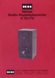
4. Pink noise from 75 – 85 Hz<br />
This test signal “02 - Pink noise 75Hz-85Hz.mp3” is used to set the phase of a subwoofer relative to a main<br />
loudspeaker. Play the test signal through the loudspeaker/subwoofer combination and adjust the phase controls<br />
(0°, 45°, 90°, and 135°, with and without the 180° switch) on the subwoofer until the lowest level is observed at the<br />
listening position. The level can be measured using a microphone and mixing console metering, a sound level meter,<br />
acoustic test equipment, or simply listen to it. Once the worst case has been found, flip the 0°/180°switch to the other<br />
setting. Verify that the setting is appropriate by repeating this process <strong>for</strong> each loudspeaker/subwoofer combination in<br />
the system.<br />
SPL<br />
(dB)<br />
75 85<br />
f (Hz)<br />
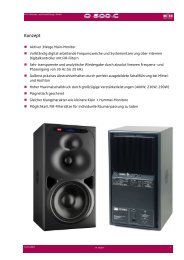
5. Pink noise 60 – 120 Hz<br />
This test signal “03 - Pink noise 60-120Hz.mp3” is used to verify the settings resulting from the above two<br />
procedures. It can reveal problems at the crossover frequency. When the bass management in the subwoofer is<br />
disabled, there should be no significant audible difference in the level of pink noise sound. If there is a difference in<br />
level, the above two level and phase procedures should be repeated. There will always be a small difference in tonality<br />
when the bass management is enabled or disabled as the loudspeaker and subwoofer will have different co<strong>up</strong>ling to the<br />
room due to their different locations.<br />
Additionally, when played loud, this test signal can be used <strong>for</strong> testing <strong>for</strong> rattles in the room. Find the source of the<br />
rattle and stop it by adding damping material, tightening <strong>up</strong> the screws, or applying (duct/gaffer) tape.<br />
SPL<br />
(dB)<br />
60 120<br />
f (Hz)<br />
<strong>TEST</strong> <strong>SIGNALS</strong> <strong>for</strong> <strong>Setting</strong> <strong>up</strong> <strong>Subwoofer</strong>-<strong>based</strong> <strong>Systems</strong> 3
6. Broadband pink noise<br />
Pink noise has equal power in each octave so the power density decreases at a rate of 3 dB per octave. The spectrum of<br />
pink noise is similar to that of the long-term average of typical music signals, and is more “loudspeaker-friendly” than<br />
white noise.<br />
This test signal “04 - Pink noise.mp3” is very good at revealing tonal differences between loudspeakers or subwoofers<br />
located in different positions in the room or between different loudspeakers or subwoofers. Ideally the sound should be<br />
the same from each loudspeaker or subwoofer in the system.<br />
It is also possible to hear the additional bass extension of the system when the bass management in the subwoofer is<br />
enabled.<br />
SPL<br />
(dB)<br />
10<br />
f (Hz)<br />
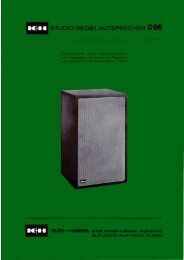
7. Low-passed Dirac impulse train<br />
An impulse is ideally infinitely narrow and infinitely tall. A Dirac impulse is a digital representation of an impulse and<br />
looks like this: 1 0 0 0 0 0 0 0. A Dirac impulse train is a set of equally-spaced Dirac impulses and looks like this:<br />
1 0 1 0 1 0 1 0. This signal is then low-pass filtered so it can be used to reveal problems such as 360° phase difference.<br />
In some situations it is possible <strong>for</strong> the main loudspeaker and subwoofer to be in-phase at the crossover frequency, but<br />
have a delay between them of one or more cycles at the listening position. This causes impulsive sounds to be smeared<br />
in the time domain. The following plots show a low-pass filtered Dirac impulse with and without a one cycle delay at<br />
80 Hz (12.5 ms) between the loudspeaker and subwoofer at the listening position.<br />
<strong>TEST</strong> <strong>SIGNALS</strong> <strong>for</strong> <strong>Setting</strong> <strong>up</strong> <strong>Subwoofer</strong>-<strong>based</strong> <strong>Systems</strong> 4
Impulse response with no delay<br />
Impulse response with 12.5ms (80 Hz) delay<br />
between the loudspeaker and subwoofer<br />
This test signal “05 - Low passed Dirac impulse train.mp3” can be used to identify if there is a 360° phase change<br />
between the loudspeaker and the subwoofer. To overcome this audible problem, reduce the difference in the distances<br />
of the loudspeaker and subwoofer cabinets from the listening position, and then set the phase and level using the first<br />
two test signals shown above.<br />
8. Kick drum track<br />
This test signal “06 - Kick drum.mp3” can be used in the same way as the low-pass filtered Dirac impulse train. It is a<br />
real-world version of the artificial low-pass filtered Dirac impulse train presented above. It is additionally useful <strong>for</strong><br />
observing the low frequency transient per<strong>for</strong>mance of the subwoofer and <strong>for</strong> listening <strong>for</strong> rattles in the room.<br />
<strong>TEST</strong> <strong>SIGNALS</strong> <strong>for</strong> <strong>Setting</strong> <strong>up</strong> <strong>Subwoofer</strong>-<strong>based</strong> <strong>Systems</strong> 5
Georg <strong>Neumann</strong> GmbH reserve the right to change product specifications without notice. Exceptions and omissions excluded.<br />
Reproduction in any manner whatsoever without the written permission of Georg <strong>Neumann</strong> GmbH is strictly <strong>for</strong>bidden.<br />
Georg <strong>Neumann</strong> GmbH.<br />
Ollenhauerstrasse 98, 13403 Berlin, Germany.<br />
Tel: +49 (30) 41 77 24-0<br />
Fax: +49 (30) 41 77 24-50<br />
E-Mail: headoffice@neumann.com<br />
Web: www.neumann.com<br />
Version: 03<br />
Date: 5-May-2011<br />
Language: English