PC 50 - bursr.com
PC 50 - bursr.com
PC 50 - bursr.com

You also want an ePaper? Increase the reach of your titles
YUMPU automatically turns print PDFs into web optimized ePapers that Google loves.
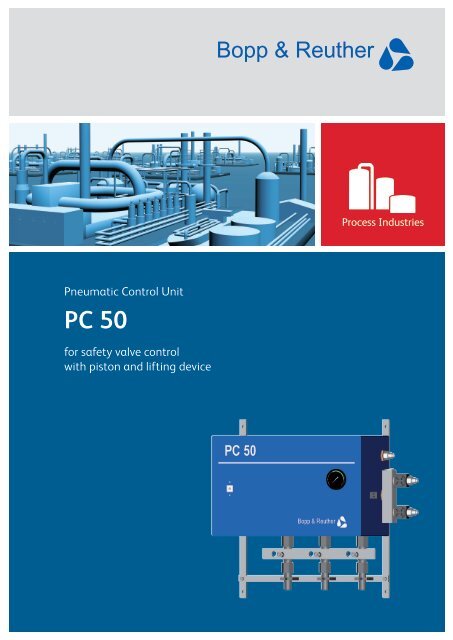
Pneumatic Control Unit<br />
<strong>PC</strong> <strong>50</strong><br />
for safety valve control<br />
with piston and lifting device
2<br />
Controlled safety valves<br />
Controlled safety valves are used primarily where standard<br />
spring-loaded safety valves cannot meet stringent operating<br />
conditions. Typical applications are systems with high operating<br />
pressures, increased tightness requirements, limited<br />
opening and reseating parameters, critical applications.<br />
Operation of controlled safety valves<br />
In addition to the safety valve spring the controlled safety<br />
valve is equipped with an air pressure cylinder piston. After<br />
start-up of the control unit the loading air is built up above<br />
the piston. The space below the piston can be operated either<br />
with continuously present lifting air or without lifting air.<br />
The control unit <strong>PC</strong> <strong>50</strong> operates in accordance with the closed<br />
circuit principle, i.e. the loading air discharges by reaching<br />
the engage pressure (usually set pressure). The pressure switches<br />
work as redundant multiple monitoring (e.g. 3 control<br />
lines in a 1 out of 3 principle). Once triggered, the loading air<br />
is released thus removing the additional closing force and<br />
the safety valve opens supported by the lifting air present<br />
below the piston or without lifting air and as a spring loaded<br />
safety valve with its own opening characteristics. In case of<br />
air supply failure controlled safety valves operate exactly like<br />
direct spring loaded safety valves. The control unit <strong>PC</strong> <strong>50</strong><br />
and the controlled safety valves fully meet the requirements<br />
according to DIN EN ISO 4126-5, AD 2000-A2 and TRD 421.<br />
Pneumatic Control Unit <strong>PC</strong> <strong>50</strong><br />
The use of the pneumatic control <strong>PC</strong> <strong>50</strong> is to control safety<br />
valves with modular differential surface double acting<br />
piston types .26ak (see page 5) or safety valve SiZ 2<strong>50</strong>7<br />
with integrated differential surface piston.<br />
Benefits <strong>PC</strong> <strong>50</strong><br />
• Quick response times<br />
• Minimal opening and reseating difference<br />
• High setting accuracy (low tolerance)<br />
• Good repeat accuracy<br />
• High tightness of the safety valve up to set-pressure<br />
• Stabilized function of the safety valve<br />
• Testing of reliability during operation by integrated test<br />
valve group with locking bar<br />
• No air consumption during working condition<br />
• Minimised down times<br />
• Reduced and restricted hysteresis<br />
Special qualities of the pressure switches<br />
• Frictionless force balanced design<br />
• High setting accuracy of the set-pressure<br />
• Good repeat accuracy of the set-pressure<br />
Benefits of controlled safety valves<br />
• Improvement of the static performance, e.g. increased<br />
tightness up to valve opening, high setting accuracy, and<br />
precise repetition of the set pressure thus improving operating<br />
efficiency.<br />
• Improvement of the dynamic performance, e.g. reduction<br />
of the opening and reseating hysteresis, stabilisation of<br />
the valve blow-off, controlled safety valve opening below<br />
the set pressure, controlled overflow with pressure maintenance<br />
improving operating efficiency and reducing down<br />
time.<br />
• Requirements in high operating pressure or the size of<br />
the safety valve, may require the use of controlled safety<br />
valves while still guaranteeing operational safety.<br />
• With the use of the control unit, the operating pressures<br />
can be staggered in multiple valve applications increasing<br />
the level of control on the system and avoiding unnecessary<br />
loss of medium.<br />
• In-service inspection (e.g. plant supervision test) is possible<br />
without additional equipment. The setting of the control<br />
unit (pressure switch and opening force reserve) as well as<br />
the safety valve set pressure may be tested while installed<br />
in the plant.<br />
Approvals<br />
• TÜV type approval<br />
• Safety devices against overpressure TRD 421<br />
• CE approval acc. PED 97/23/EG<br />
Controlled safety valves with <strong>PC</strong> <strong>50</strong>
Flow diagram <strong>PC</strong> <strong>50</strong> in operating position with one safety valve<br />
List of <strong>com</strong>ponents <strong>PC</strong> <strong>50</strong> (see Flow diagram above)<br />
Part Description<br />
1 Pressure switch<br />
2 Shut off valve with test connection<br />
3 Pressure reducer with fine filter<br />
3a Ball valve<br />
6 Quick air vent valve (lifting)<br />
7 Throttle<br />
8 Quick air vent valve (loading air)<br />
9 Time delay valve<br />
10 Locking bar<br />
12 Key lever valve<br />
16 Pressure gauge for supply air<br />
17 Pressure gauge for control air<br />
18 Pressure gauge for loading air<br />
20 3-way ball valve<br />
21 Control air line<br />
22 Control air line<br />
23 Lifting air connection<br />
24 Loading air connection<br />
25 Pressure tapping line<br />
Optional equipment <strong>PC</strong> <strong>50</strong><br />
Description<br />
Brass and bronze free unit<br />
Hand lever valve with test gauge for testing of the safety valve<br />
Electrical heating (with/without explosion-proof)<br />
2nd thermostat for remote control (with/without explosion proof)<br />
Solenoid valve for remote operation (with /without explosion proof)<br />
Double pressure isolation<br />
Pressure transmitter for protection of the pressure switch<br />
(protection against corrosive or viscous medium)<br />
Pressure tapping line with flange or threaded connection<br />
Electric signal for control unit operation (at set pressure)<br />
Electric monitoring of the control mechanism<br />
3a 3<br />
12 16 17 17 17 18<br />
9<br />
6<br />
1 1 1<br />
8<br />
3
4<br />
Control Unit <strong>PC</strong> <strong>50</strong> - Dimensions<br />
dimensions <strong>PC</strong> <strong>50</strong><br />
Connections<br />
Item Description Dimensions of Connections, Explanations<br />
1 Supply air connection G 1/2 female; supply air pressure range: 2,5 to 10 bar(g)<br />
2 Loading air connection G 3/4 female; loading air pressure range: 2,5 to 5 bar(g)<br />
3 Lifting air connection G 1/2 female<br />
4 Makers plate<br />
5 System pressure shut-off valve with testing connection According to DIN 16271<br />
6 Pressure tapping line Weld end acc. to DIN 2559 pipe size of 26,9 x 3,2 material 13CrMo44<br />
(1.7335)<br />
7 Mounting frame For installation of the control unit in a vibration free site<br />
8 Indication of function Shows the operation status of the control unit<br />
10 Locking bar Allows the closing of only one shut-off valve<br />
11 Lifting air valve Position of three-way valve acc. connection mode (page 7 type code 3)<br />
Technical Data<br />
Time-lag less than 0,15 sec.<br />
Switch reset value up to 3% of the end of scale value of the pressure switch (see type code page 7)<br />
Repeat accuracy > 99,<strong>50</strong>%<br />
Setting accuracy > 99%
Pneumatic piston .26ak<br />
Test connection<br />
Loading air connection<br />
Loading piston<br />
Lifting piston<br />
Lifting air connection<br />
Spring<br />
Blocking nut<br />
Spindle coupling<br />
Pneumatic piston<br />
mounting plate<br />
Pneumatic piston .26ak sectional view<br />
Lifting valve assembly LG2 and LG3<br />
Lifting valve assembly LG2<br />
• Differential surface double acting piston for accurate<br />
performance (area of loading piston larger than area of<br />
lifting piston).<br />
• On failure of supply air the control air is vented off the<br />
pneumatic system, the piston spring is forcing apart the<br />
piston halves and the piston stem is free (flying piston).<br />
The valve operates as a spring-loaded safety valve.<br />
• Five piston sizes cover all valve dimensions and pressure<br />
ranges.<br />
• The piston integrated blocking nut allows for safety valve<br />
gagging for e.g. pressure system hydro test.<br />
• A post installation modification of existing spring loaded<br />
safety valves is possible to optimize the functional performance,<br />
e.g. in case of increasing operating pressures.<br />
• The piston assembly .26ak is an approved optional design<br />
for Bopp & Reuther safety valves with TÜV-type test and<br />
CE marking.<br />
• The lifting valve assembly LG2 has one loading air inlet<br />
and one lifting air inlet, with outlets for two valves‘ loading<br />
and lifting air. The LG3 has outlets for three valves‘<br />
loading and lifting air.<br />
• The LG3 is required for the connection of three safety<br />
valves to one <strong>PC</strong> <strong>50</strong> control unit with easy operation.<br />
The LG2 may be used for two safety valves.<br />
• The 3/2-way valves built in the lifting valve assembly<br />
enable selection of all pneumatic system connection<br />
mode (see type code page 7), i.e. for each valve separate<br />
lifting air on/off.<br />
• Lifting of a single safety valve is possible without change<br />
of production function of the 2nd or 3rd valve.<br />
• In case of long pipe runs between control unit and<br />
multiple valves the piping effect may be reduced with a<br />
lifting and loading air manifold within short distance of<br />
the safety valves.<br />
5
6<br />
Example of a steam generator application<br />
In the above application two controlled safety valves are<br />
installed on the drum and one controlled safety valve on the<br />
superheater. The set pressure of the superheater safety valve<br />
is lower <strong>com</strong>pared to the drum safety valve and is in operation<br />
with lifting air on (connection mode N, see type code page 7).<br />
In order to ensure that no condensate will flow back to the<br />
main pressure system line the control unit must be placed at a<br />
lower elevation than the main steam pipe.<br />
Pressure tapping lines are typically located on the higher elevation<br />
of the pressure system, offset to each other and water<br />
seals are to be used when utilizing hot mediums. The pressure<br />
tapping lines shall be installed in horizontal direction or downwards<br />
to the steam pipe. The vertical upward tapping line<br />
part is always hot and has condensate return which drips in<br />
the steam pipe. These hot segments of the pressure tapping<br />
lines have to be insulated. Remaining pressure tapping lines<br />
are generally not be insulated.<br />
The connection mode of the drum valves is arrangement T<br />
(see type code page 7), i.e. loading air only. The pressure<br />
tapping lines are connected to the drum and the superheater.<br />
In case the steam system pressure triggers the set pressure of<br />
any pressure switch (1 out of 3), the loading air is vented from<br />
safety valve cylinders. The superheater safety valve opens first<br />
supported by the lifting air, while the drum safety valves are<br />
still closed due to higher spring setting.<br />
The sole opening of the superheater safety valve covers many<br />
relief cases with short pressure increase and cooling of the<br />
steam generation system is further ensured, because steam is<br />
relieved at the system end.<br />
Should the pressure in the steam generator increase further,<br />
the drum safety valves open against spring setting and the<br />
total generated steam capacity is discharged to retain safe<br />
pressure levels.
Type code<br />
1 Product type <strong>PC</strong> <strong>50</strong><br />
2 Pressure Range<br />
3 Connection mode<br />
4<br />
5<br />
Key lever valve for<br />
main valve test<br />
Magnetic lifting<br />
device<br />
6 Electrical heating<br />
7 Special design<br />
8<br />
9<br />
Pressure tapping<br />
connection<br />
Materials of<br />
construction<br />
06 >0,1 to 0,25 bar (2,5 bar*)<br />
07 >0,25 to 0,4 bar (2,5 bar*)<br />
08 >0,4 to 0,6 bar (2,5 bar*)<br />
09 >0,6 to 1 bar (2,5 bar*)<br />
10 >1 to 4 bar<br />
11 >4 to 6 bar<br />
12 >6 to 10 bar<br />
13 >10 to 16 bar<br />
14 >16 to 25 bar<br />
15 >25 to 40 bar<br />
16 >40 to 60 bar<br />
17 >60 to 100 bar<br />
18 >100 to 1<strong>50</strong> bar (160 bar*)<br />
19 >1<strong>50</strong> to 200 bar (2<strong>50</strong> bar*)<br />
20 >200 to 2<strong>50</strong> bar (400 bar*)<br />
*<br />
for the calculation of the pressure switch<br />
reset value instead of the scale final value<br />
N1 1 safety valve operated with loading air<br />
and lifting air<br />
T1 1 safety valve operated with loading air<br />
and without lifting air<br />
N2 2 safety valves operated with loading air<br />
and lifting air<br />
T2 2 safety valves operated with loading air<br />
and without lifting air<br />
TN 2 safety valves operated with loading air<br />
1 safety valves operated with lifting air and<br />
1 safety valve operated without lifting air<br />
SA safety shut-off valve<br />
0 without<br />
1 with<br />
0 without<br />
1 with<br />
2 explosion proof<br />
0 without<br />
1 with<br />
2 with additional thermostat<br />
3 explosion proof<br />
4 explosion proof with additional thermostat<br />
0 without<br />
1 with<br />
0 without test valve group<br />
1 weld end<br />
2 flange acc. to DIN/EN<br />
3 flange acc. to ASME<br />
0 Standard<br />
1 brass and bronze free<br />
2 non-magnetic<br />
Order code:<br />
Please<br />
specify:<br />
Ordering example<br />
<strong>PC</strong> <strong>50</strong><br />
16<br />
T1<br />
0<br />
1<br />
2<br />
0<br />
1<br />
1<br />
<strong>PC</strong><strong>50</strong>16.T1.012.011<br />
Setting for pressure switches:<br />
<strong>50</strong> / 45 / 45 bar (ü)<br />
7
Bopp & Reuther makes industrial processes safe and efficient.<br />
We develop and manufacture shut off valves, safety and<br />
control valves for the process industry, conventional power<br />
stations, the nuclear industry and other applications. Our<br />
products are supported by a worldwide service network.<br />
Bopp & Reuther<br />
Sicherheits- und Regelarmaturen GmbH<br />
Carl-Reuther-Straße 1<br />
68305 Mannheim<br />
Germany<br />
Phone +49 621 76220-100<br />
Fax +49 621 76220-120<br />
www.<strong>bursr</strong>.<strong>com</strong><br />
sales@<strong>bursr</strong>.<strong>com</strong><br />
MANNHEIM<br />
FRANKFURT<br />
70 km<br />
N<br />
W O<br />
© Bopp & Reuther Sicherheits- und Regelarmaturen GmbH. All rights reserved. Bopp & Reuther reserves the right to make technical changes without prior notice. All text and images are protected<br />
by copyright. Reproduction of any part of this document is strictly prohibited. We cannot be held responsible for any omissions or inaccuracies as a result of printing or <strong>com</strong>position errors.<br />
S<br />
04_2012 / <strong>PC</strong><strong>50</strong> en