Isolated dc-dc converters with high-output voltage for TWTA - Ivo Barbi
Isolated dc-dc converters with high-output voltage for TWTA - Ivo Barbi
Isolated dc-dc converters with high-output voltage for TWTA - Ivo Barbi

You also want an ePaper? Increase the reach of your titles
YUMPU automatically turns print PDFs into web optimized ePapers that Google loves.
<strong>Isolated</strong> <strong>dc</strong>-<strong>dc</strong> Converters <strong>with</strong> High-Output Voltage<br />
For <strong>TWTA</strong> Telecommunication Satellite Applications<br />
Roger Gules and <strong>Ivo</strong> <strong>Barbi</strong><br />
Federal University of Santa Catarina -UFSC<br />
Power Electronic Institute - INEP<br />
P.O. Box 5 119 - 88010-970 - Florian6polis-SC-Brail<br />
Phone: +55-48-33 1-9204 - Fax: +55-48-234-5422<br />
E-mail: roger@,ineD.ufsc.br Intemet: http://www.ineD.ufsc.br<br />
Abstract-Two alternatives <strong>for</strong> the implementation of an<br />
isolated <strong>dc</strong>-<strong>dc</strong> converter <strong>with</strong> <strong>high</strong> <strong>output</strong> <strong>voltage</strong> are presented.<br />
The proposed topologies are especially well adapted <strong>for</strong> the<br />
implementation of Travelling Wave Tube Amplifiers (<strong>TWTA</strong>)<br />
utilized in telecommunication satellite applications. The<br />
<strong>converters</strong> studied follow different principles and the main<br />
operation aspect of each topology is analyzed. The experimental<br />
results obtained from two prototypes <strong>with</strong> 150W of <strong>output</strong><br />
power, total <strong>output</strong> <strong>voltage</strong> of 3.2kV and an input <strong>voltage</strong><br />
variable from 26V until 44V are presented. The efficiency<br />
obtained operating <strong>with</strong> the nominal <strong>output</strong> power is <strong>high</strong>er<br />
than 93.4 YO <strong>for</strong> both structures.<br />
I. INTRODUCTION<br />
There are different applications where is necessary the<br />
use of <strong>high</strong> level DC <strong>voltage</strong>s (thousands volt). Typical<br />
examples are COz laser-based systems, X-ray equipment <strong>for</strong><br />
medical and industrial applications, cathode-ray-tubes and<br />
telecommunication equipment <strong>with</strong> vacuum tubes, like<br />
Travelling Wave Tube (TWT) utilized in communication<br />
satellite.<br />
The choice of most adequate solution depends of the<br />
design requirements of each specific application as cost,<br />
mass, volume, efficiency, reliability, etc.<br />
Other point in the choice of the converter is the <strong>high</strong><strong>voltage</strong><br />
circuit non-idealities that present an important<br />
influence in the converter operation and the topology adopted<br />
must integrate these intrinsic parameters into the operation<br />
principle. Besides the leakage inductance, the <strong>high</strong>-<strong>voltage</strong><br />
trans<strong>for</strong>mer also presents a winding capacitance referred to<br />
the primary side that due to the <strong>high</strong> number of tums in the<br />
secondary winding and the <strong>high</strong> trans<strong>for</strong>mer tums ratio,<br />
becomes important in-the converter operation. Fig. 1 presents<br />
the <strong>high</strong>-<strong>voltage</strong> trans<strong>for</strong>mer simplified model constituted by<br />
the primary leakage inductance (L d), magnetizing inductance<br />
(L,,,)and the equivalent capacitance referred to the primary<br />
side (C,) [ 1,2].<br />
-HK<br />
nl: n2<br />
Fig. 1. Simplified equivalent circuit of the <strong>high</strong> <strong>voltage</strong><br />
and <strong>high</strong> frequency trans<strong>for</strong>mer.<br />
In the particular case of communication satellite<br />
applications studied in this paper, severe requirements must<br />
be attended due to the environmental conditions, reliability,<br />
mechanical and electrical specifications.<br />
The launch cost .is very <strong>high</strong> and there is a permanent<br />
interest in the efficiency improvement and reduction of the<br />
mass and volume in satellite equipment. High efficiency is<br />
important to achieve since the primary power source of a<br />
satellite is in general a solar array and batteries, presenting an<br />
important impact on total mass, volume and cost.<br />
The final stage amplifier in the transponder of the<br />
communication satellite is the Travelling Wave Tube<br />
Amplifier (<strong>TWTA</strong>). In this kind of satellite, the payload mass<br />
and power consumption is mainly given by the presence of<br />
the <strong>TWTA</strong> which can represent about 35% of the total mss<br />
and from 70% to 90% of the overall DC power consumption<br />
[3]. There<strong>for</strong>e, the design of <strong>TWTA</strong> has been continuously<br />
improved in order to realize more light and efficient<br />
equipment.<br />
The <strong>TWTA</strong> consist of a microwave amplifier tube TWT<br />
mainly determining the radio frequency (RF) per<strong>for</strong>mance<br />
and by an Electronic Power Conditioner (EPC) <strong>for</strong> power<br />
matching of the DC interface. The <strong>high</strong> <strong>voltage</strong> <strong>dc</strong>-<strong>dc</strong><br />
converter is the most important part of the EPC because it is<br />
the critical point in the design of a <strong>high</strong> efficiency and<br />
competitive <strong>TWTA</strong>. The input <strong>voltage</strong> of the <strong>dc</strong>-<strong>dc</strong> converter<br />
is an unregulated low <strong>voltage</strong> bus (from 26V until 44V) and<br />
in order to produce the TWT supply <strong>voltage</strong>s there are<br />
multiple <strong>output</strong>s in the <strong>dc</strong>-<strong>dc</strong> converter, resulting in a total<br />
cathode-anode <strong>voltage</strong> of thousands volts.<br />
11. HIGH VOLTAGE DC-DC CONVERTERS<br />
There are different altematives <strong>for</strong> the implementation of<br />
an isolated <strong>dc</strong>-<strong>dc</strong> converter <strong>with</strong> <strong>high</strong> <strong>output</strong> <strong>voltage</strong>,<br />
however there are some operations characteristics that the<br />
converter must present in order to obtain <strong>high</strong> efficiency and<br />
reduced volume and mass. The main operation characteristics<br />
are:<br />
High switching frequency in order to reduce the reactive<br />
elements likes inductors, filter capacitors and the power<br />
trans<strong>for</strong>mer.<br />
Soft-commutation in the power switches, avoiding the<br />
reduction of the efficiency <strong>with</strong> the increment of the<br />
switching frequency.<br />
0-7803-6618-2/011$10.000 2001 IEEE 296
Integration in the converter operation of the intinsic<br />
elements of the <strong>high</strong>-<strong>voltage</strong> power trans<strong>for</strong>mer like<br />
leakage inductance and distributed capacitance, avoiding<br />
the dissipation of the energy stored in these elements.<br />
Constant switching frequency, allowing the choice of an<br />
optimum switching frequency <strong>with</strong> respect to the mass,<br />
volume and efficiency.<br />
0 Voltage source <strong>output</strong> characteristic, because the multiple<br />
<strong>high</strong>-<strong>voltage</strong> <strong>output</strong>s necessaries <strong>for</strong> to supply the TWT<br />
become unfeasible the utilization of <strong>high</strong>-<strong>voltage</strong> <strong>output</strong><br />
filter inductors <strong>for</strong> a current source <strong>output</strong> characteristic.<br />
Others operation characteristics are also desirable in <strong>TWTA</strong><br />
application:<br />
Input current source behavior that minimizes the volume<br />
of the input filter.<br />
A step-up <strong>output</strong> characteristic, allowing the reduction of<br />
the trans<strong>for</strong>mer turns ratio and minimizing the effects of<br />
the trans<strong>for</strong>mer equivalent capacitance in the converter<br />
operation.<br />
Good load regulation and support a large variation of the<br />
input <strong>voltage</strong>.<br />
Considering as choice criterion of the <strong>converters</strong> all<br />
operation characteristics presented above, two topologies<br />
were selected and studied. Two <strong>dc</strong>-<strong>dc</strong> <strong>converters</strong> connected<br />
in series (two-stage topology) compose most part of the<br />
structures developed <strong>for</strong> this application and the first<br />
topology adopted follows this principle. The second topology<br />
studied is based on a new single-stage structure <strong>for</strong> <strong>TWTA</strong><br />
applications.<br />
111. TWO-STAGE TOPOLOGY<br />
A. Proposed Circuit<br />
The first converter that composes the two-stage topology<br />
is a regulator (normally a classical buck or boost <strong>dc</strong>-<strong>dc</strong><br />
converter). The second structure is an isolated <strong>dc</strong>-<strong>dc</strong><br />
converter operating in resonant way, generating the different<br />
<strong>high</strong> <strong>voltage</strong> <strong>output</strong>s <strong>for</strong> supply the TWT. In this case, the<br />
isolated <strong>dc</strong>-<strong>dc</strong> converter operates in an optimized operation<br />
point, <strong>with</strong> constant switching frequency and fix duty-ratio.<br />
This configuration is normally utilized due to the difficulty in<br />
to obtain <strong>high</strong> efficiency in the isolated <strong>dc</strong>-<strong>dc</strong> converter.<br />
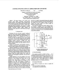
The two-stage topology studied in this work is presented<br />
in Fig.2. The first converter is a classical boost <strong>dc</strong>-<strong>dc</strong><br />
converter composed by the input inductor L power switch<br />
SI, diode D1 and a filter capacitor C The boost regulator<br />
operates <strong>with</strong> hard switching but <strong>with</strong> the utilization of a<br />
Schottky diode in its <strong>output</strong>, <strong>high</strong>-efficiency operating <strong>with</strong><br />
<strong>high</strong> switching frequency is reached.<br />
The second converter is a resonant push-pull current fed<br />
<strong>dc</strong>-<strong>dc</strong> converter composed by two power switches S and<br />
$2, an input inductor L z, a resonant capacitor C and the<br />
push-pull trans<strong>for</strong>mer. The <strong>output</strong>s are composed by fullbridge<br />
rectifier and filter capacitors. The intrinsic parameters<br />
of the trans<strong>for</strong>mer are also presented in Fig.2.<br />
The push-pull converter operates <strong>with</strong> zero current and<br />
zero <strong>voltage</strong> switching techniques (ZCWZVS). The softcommutation<br />
is not dependent of the load current because the<br />
energy stored in the magnetizing inductance per<strong>for</strong>ms the<br />
<strong>voltage</strong> transitions in the circuit capacitance.<br />
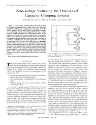
The main theoretical wave<strong>for</strong>ms of the isolated converter<br />
are presented in Fig.3.<br />
There are two resonant circuits in the operation of this<br />
converter. During the conduction of one power switch S or<br />
Sp2 (to-tl), the resonance between center tap capacitor (C T)<br />
and the trans<strong>for</strong>mer leakage inductance (L d) occurs. When<br />
both power switches are turned-off (tl-t2) there is the<br />
resonance between the magnetizing inductance and the<br />
intrinsic circuit capacitance (power switches and trans<strong>for</strong>mer<br />
equivalent capacitance). The current (i) presented in Fig.3 is<br />
the current in the center tap of the push-pull trans<strong>for</strong>mer.<br />
Input <strong>voltage</strong>: Vin=26/44V<br />
Total <strong>output</strong> <strong>voltage</strong>: Vo=32o0V<br />
Nominal <strong>output</strong> power: Po=ISOW :<br />
PI=SP2=APTZOM22LZVR<br />
SI= IRFp2Y<br />
D,= 8TQlOo<br />
Reclifis diodes = MUR 1 lo0<br />
.----_.<br />
Ferrite colc ETD39-IPITIhomton<br />
Fig.2. Power circuit implemented of the two-stage topology.<br />
297
Reference [4] presents more details about the operation<br />
of this converter.<br />
VCI<br />
I<br />
The switch conduction period is represented by the<br />
relative parameter (tr). The current and <strong>voltage</strong> ef<strong>for</strong>t<br />
increase <strong>with</strong> the reduction of the switch conduction time (tr).<br />
The relative frequency F is the relationship between the<br />
resonance frequency of the leakage inductance and the center<br />
tap capacitance, <strong>with</strong> the switching frequency. This<br />
resonance occurs during the conduction of the power switch.<br />
Fr2 is the relationship between the resonant frequency of<br />
the magnetizing inductance and equivalent circuit<br />
capacitance, <strong>with</strong> the switching frequency. This resonance<br />
occurs when both switches are tumed off.<br />
Substituting the specification and parameters in (1) yields:<br />
VCI<br />
VCI<br />
11 U 0 %<br />
Fig.3. Main theoretical wave<strong>for</strong>ms.<br />
B. Simplified Design Procedure<br />
1) Specifications andparameters<br />
The following specifications are considered in the design:<br />
Input <strong>voltage</strong>:<br />
Vi,,=26/44V<br />
Total <strong>output</strong> <strong>voltage</strong><br />
V0=3200V<br />
Output power:<br />
P0=150W<br />
Push-pull switching frequency:<br />
Fs=801
,=atan.( z.Fr .(I - t ) )=0.549<br />
<strong>voltage</strong> is presented in Fig.7. The lowest efficiency obtained<br />
<strong>with</strong> nominal <strong>output</strong> power was 93.4% <strong>for</strong> the minimum<br />
input <strong>voltage</strong>.<br />
TO* *coo 25 OMS,*<br />
715 ACqc.<br />
is:<br />
The switch RMS current is:<br />
is, = ./%- = 3.09A (13)<br />
The maximum blocking <strong>voltage</strong> across the switch (VS pk)<br />
7<br />
Zn = .,/$<br />
= 1.34<br />
a<br />
Fig.5.Power switch <strong>voltage</strong> and current (25V/2A/2p/div).<br />
vs, =-<br />
cos(,)<br />
+2.V2 =IOW<br />
With the increment of the leakage inductance L d due to<br />
the constructive characteristic of the trans<strong>for</strong>mer, the<br />
capacitor CT must be lower <strong>for</strong> the same resonant frequency<br />
F, as shown in (9). Thus the parameter Zn calculated by (14)<br />
and the <strong>voltage</strong> ef<strong>for</strong>ts increase <strong>with</strong> the increment of L d.<br />
5) Output Filter Voltage Ripple<br />
The parameterized <strong>output</strong> <strong>voltage</strong> ripple is calculated by<br />
(16) and (17).<br />
-<br />
AV=<br />
AVc,,*C;F, -<br />
_-.<br />
1 2<br />
I O z F;cos(~)<br />
a=otang( w.F,.(l- t,) )<br />
Where:<br />
I, - Average <strong>output</strong> current.<br />
CO - Filter capacitor<br />
AV,, - Output <strong>voltage</strong> ripple<br />
C. Experimental Results<br />
A laboratory prototype was implemented following the<br />
optimized design procedure developed and some wave<strong>for</strong>ms<br />
obtained from this prototype operating <strong>with</strong> the minimal<br />
input <strong>voltage</strong> and the nominal <strong>output</strong> power are presented.<br />
The details about the power circuit implemented are shown in<br />
Fig.2. A typical configuration of load resistance representing<br />
the TWT <strong>for</strong> the test of the power supply is used. The<br />
different current i d <strong>voltage</strong> level in each <strong>output</strong> and the<br />
nominal <strong>output</strong> power are defined by the kind of TWT<br />
considered in the design.<br />
Fig.5 presents the soft-commutation obtained in the<br />
power switch of the push-pull converter. Fig.6 shows the<br />
<strong>voltage</strong> and current in a rectifier diode of the push-pull. The<br />
efficiency curve of the two-stage topology (boost and Pushpull)<br />
operating <strong>with</strong> nominal <strong>output</strong> power and variable input<br />
S.<br />
Fig.6. Rectifier diode <strong>voltage</strong> and current (lOOV/50mA/2p Jdiv).<br />
9s<br />
94.5<br />
t1W) 94<br />
93.5<br />
94-s-<br />
93<br />
25 30 3s<br />
Vin (V)<br />
40 45<br />
Fig.7. Efficiency operating <strong>with</strong> nominal <strong>output</strong> power<br />
and variable input <strong>voltage</strong>.<br />
IV-SINGLE STAGE TOPOLOGY<br />
The main drawback of the two-stage topologies is the<br />
converter series connection that causes a reduction of the<br />
overall efficiency. Both <strong>converters</strong> must present a very <strong>high</strong><br />
efficiency (close to 96%) in order to maintain an adequate<br />
efficiency <strong>for</strong> a satellite communication application (<strong>high</strong>er<br />
than 92%).<br />
There<strong>for</strong>e, a single stage topology can result in a <strong>high</strong>er<br />
efficiency and a lower mass and volume than the two-stage<br />
topology. However, the isolated <strong>dc</strong>-<strong>dc</strong> converter operates<br />
<strong>with</strong> a variable operation point (non-optimum) due to the<br />
converter's regulation action. Thus, the single stage topology<br />
candidate must present all suitable operation characteristics<br />
<strong>for</strong> <strong>high</strong>-<strong>voltage</strong> applications described be<strong>for</strong>e and maintain a<br />
<strong>high</strong> efficiency in all range of the input <strong>voltage</strong>.<br />
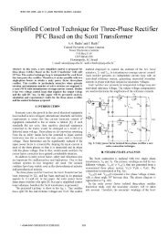
A. Proposed Circuit<br />
For the implementation of a competitive <strong>high</strong>-<strong>voltage</strong><br />
isolated <strong>dc</strong>-<strong>dc</strong> converter, a single-stage <strong>high</strong>-efficiency<br />
topology is proposed. The power circuit adopted, presented in<br />
299
-____.<br />
Fig.8, is. based -on the current-fed push-pull <strong>dc</strong>-<strong>dc</strong><br />
converter operating <strong>with</strong> PWM modulation, active clamping<br />
and ZVS commutation [SI.<br />
Two main switches (S p1 and SP2), two auxiliary clamping<br />
switches (Sal and Sa), a clamping capacitor C G and a pushpull<br />
trans<strong>for</strong>mer compose the converter. The current feeding<br />
is provided by the <strong>voltage</strong> source V in in series <strong>with</strong> the input<br />
inductor Li,. The <strong>output</strong>s are <strong>for</strong>med by full-bridge rectifiers<br />
and by filter capacitors. The anti-parallel diode and intrinsic<br />
capacitance of the MOSFET are used in the circuit operation.<br />
The intrinsic parameters of the trans<strong>for</strong>mer are also presented<br />
in Fig.8.<br />
The main operation wave<strong>for</strong>ms are shown in Fig.9.<br />
Fig.8. Power circuit implemented of the single-stage topology.<br />
- - - __<br />
The- active clamping allows the operation <strong>with</strong> softcommutation<br />
in all switches until a minimum load and the<br />
<strong>voltage</strong> across the blocking switch is equal the clamping<br />
<strong>voltage</strong>.<br />
An important characteristic of this structure is to operate<br />
<strong>with</strong> a main switch duty-ratio (D) <strong>high</strong>er than and lower than<br />
0.5 (<strong>with</strong> overlapping and <strong>with</strong>out overlapping). The<br />
auxiliary switches operate in a complementary way in<br />
relation the respective main switch.<br />
For a main switch duty-ratio lower than 0.5, the converter<br />
operates like a sepic <strong>dc</strong>-<strong>dc</strong> converter and <strong>with</strong> a step-down<br />
<strong>output</strong> characteristic. For the operation <strong>with</strong> a main switch<br />
duty-cycle <strong>high</strong>er than 0.5, the converter operates like an<br />
isolated boost converter <strong>with</strong> a step-up <strong>output</strong> characteristic.<br />
There<strong>for</strong>e, this converter does not present inrush current <strong>for</strong> a<br />
progressive variation of the duty-cycle and support a large<br />
variation of the input <strong>voltage</strong>.<br />
There is the resonance between the leakage inductance<br />
and the parasitic trans<strong>for</strong>mer capacitance when both main<br />
switches are conducting. During this period the input<br />
inductance (Lin) stores energy and the oscillations does not<br />
present influence in the converter's operation.<br />
I .<br />
"spl " Sal ' Spl<br />
Gat ,<br />
, ' Sp2 Sa2 I'SP2 '* I<br />
' -4.T " M.T,, 4.T , , .PI 4" '<br />
T ><br />
D.T<br />
>'<br />
Fig.9. Main theoretidl wave<strong>for</strong>ms.<br />
t<br />
B. Simplified Design Procedure<br />
1) Specifications and parameters<br />
The following specifications are considered in the design:<br />
Input <strong>voltage</strong>:<br />
Vin=26144V<br />
Total <strong>output</strong> <strong>voltage</strong><br />
V,=3200V<br />
Output power:<br />
P,=150W<br />
Push-pull switching frequency: FS=80k&<br />
The parameters of the implemented circuit are:<br />
Magnetizing inductance:<br />
Lm=85W<br />
Leakage inductance:<br />
Ld26@<br />
Winding capacitance:<br />
Cp=8.75nF<br />
2) Operation point of the Push-pull converter<br />
The <strong>output</strong> <strong>voltage</strong> referred to the primary side (V op)<br />
adopted in the design is equal to SOV, considering the main<br />
300
switch duty-ratio <strong>high</strong>er than 0.5 and a step-up <strong>output</strong><br />
characteristic.<br />
The static gain, operating <strong>with</strong> the minimum and<br />
maximum input <strong>voltage</strong> are determined respectively by:<br />
gm = -%- = -<br />
50<br />
= 1.9231<br />
Vin,, 26<br />
vop 50<br />
4, =-- - - = I. I364<br />
Vin,, 44<br />
(19)<br />
The nominal input current operating <strong>with</strong> the minimum<br />
and maximum input <strong>voltage</strong>, considering the operation<br />
<strong>with</strong>out losses is:<br />
Po<br />
Iin, =-=5.77A<br />
Vin (20)<br />
Po<br />
Iin, = - = 3.41A<br />
Vin m,<br />
The parameter y represents a reduction of the effective<br />
converter duty-ratio due to the presence of the active<br />
clamping circuit. This characteristic is common in the most<br />
part of the ZVS-PWM <strong>converters</strong>. This parametet is<br />
proportional to the leakage inductance and input current.<br />
For the minimum and maximum input <strong>voltage</strong> results:<br />
Iin, * L, . F,<br />
Yvm = = 0.08308<br />
VOP<br />
lin, . L, . F, =<br />
Y, =<br />
0.04909<br />
VOP<br />
The nominal converter duty-ratio <strong>for</strong> the minimum and<br />
maximum input <strong>voltage</strong> is:<br />
Auxiliary switch:<br />
iSa, = lin, .&e,/-12 = 0.945A (29)<br />
4) Current ef<strong>for</strong>ts operating <strong>with</strong> the maximum input<br />
<strong>voltage</strong><br />
Main switch:<br />
iSp, = lin, . -. ,/15.y,+13-7.d, ~2.4324 (30)<br />
12<br />
Auxiliary switch:<br />
5) Soff-commutation range<br />
The minimal input current that maintains the softcommutation<br />
is defined by:<br />
Where:<br />
Z, =E (33)<br />
The soft-commutation range increase <strong>with</strong> Z , and Ld. The<br />
soft-commutation was obtained in all input <strong>voltage</strong> variation<br />
range and in an adequate load variation range.<br />
6) Output Filter Voltage Ripple<br />
The parameterized <strong>output</strong> <strong>voltage</strong> ripple is variable <strong>with</strong><br />
the static gain (4) and calculated by (34).<br />
2) Voltage ef<strong>for</strong>ts<br />
The clamping <strong>voltage</strong> operating <strong>with</strong> nominal <strong>output</strong><br />
power and minimum and maximum input <strong>voltage</strong> is:<br />
2<br />
V,, = Vin,, - = 147V<br />
l-dvm<br />
(26)<br />
L<br />
V,, = fin,, = 112.5V<br />
1 - d”X<br />
Thus the maximum blocking <strong>voltage</strong> across the active<br />
switches is equal to 147V.<br />
3) Current ef<strong>for</strong>ts operating <strong>with</strong> the minimum input<br />
<strong>voltage</strong><br />
Main switch:<br />
Where:<br />
I, - Average <strong>output</strong> current.<br />
CO - Filter capacitor<br />
AVco - Output <strong>voltage</strong> ripple<br />
C. Experimental Results<br />
A laboratory prototype was implemented following an<br />
optimized design procedure developed and some wave<strong>for</strong>ms<br />
obtained operating <strong>with</strong> the minimal input <strong>voltage</strong> and the<br />
nominal <strong>output</strong> power are presented. The details about the<br />
power circuit implemented are presented in Fig.8.<br />
Fig.10 shows the main switch current and <strong>voltage</strong><br />
wave<strong>for</strong>ms. The soft-commutation is obtained and the<br />
maximum switch <strong>voltage</strong> is equal the clamping <strong>voltage</strong>.<br />
The auxiliary switch <strong>voltage</strong> and current wave<strong>for</strong>ms are<br />
presented in Fig. 1 1. The auxiliary switch also presents soft-<br />
301
commutation and the RMS current and the conduction losses<br />
are very low.<br />
The efficiency curve operating <strong>with</strong> nominal <strong>output</strong><br />
power and variable input <strong>voltage</strong> is present in Fig.12. The<br />
lowest efficiency obtained <strong>with</strong> nominal <strong>output</strong> power was<br />
94.1 Yo.<br />
TeK StOL 25 OMS/5<br />
2<br />
503 ncqs<br />
FiglO. Main switch <strong>voltage</strong> and current (5OV/2A/2pddiv).<br />
TeK 5tOP 25 OMW5<br />
114 ncqs<br />
I<br />
The proposed <strong>converters</strong> are suitable <strong>for</strong> low input <strong>voltage</strong><br />
applications, because the blocking <strong>voltage</strong> switch is <strong>high</strong>er<br />
than two times the input <strong>voltage</strong> <strong>for</strong> both structures.<br />
The operation characteristics were verified by the<br />
implementation of the laboratory prototypes operating <strong>with</strong> a<br />
variable input <strong>voltage</strong> (26V/ 44V) and <strong>with</strong> 3.2kV of total<br />
<strong>output</strong> <strong>voltage</strong>. The lowest efficiency obtained operating <strong>with</strong><br />
the nominal <strong>output</strong> power is equal to 94.1% <strong>for</strong> the singlestage<br />
topology and equal to 93.4% <strong>for</strong> the two-stage<br />
topology. The single-stage topology proposed presents a<br />
lower mass and volume and <strong>high</strong>er efficiency than the two<br />
stages-topology studied.<br />
The <strong>output</strong> <strong>voltage</strong> ripple of the single-stage topology<br />
operating in the worst operation condition (<strong>high</strong>er static gain)<br />
was 30% <strong>high</strong>er than the two-stage topology <strong>with</strong> the same<br />
<strong>output</strong> filter.<br />
REFERENCES<br />
a<br />
I I I II/F I I I I<br />
Fig.11. Auxiliary switch <strong>voltage</strong> and current (50V/2A/2pddiv).<br />
94.9<br />
94.7<br />
94.5<br />
943<br />
94.1<br />
*<br />
93.7 93*9<br />
25 30 35 40 45<br />
Vin (V)<br />
Fig. 12. Efficiency operating <strong>with</strong> nominal <strong>output</strong> power<br />
and variable input <strong>voltage</strong>.<br />
V. CONCLUSIONS<br />
[ ‘1 B. Tala-Ighil, J-M. Nyobe-Yome and C. Glaize, “High-Voltage Variable-<br />
Frequency Double-Resonant DC-DC Converters Utilizing the<br />
l<br />
Tmsfomer Parasitic Elements,” Proceedings of the European Space<br />
Power Conference, Austria, p. 245-250, Aug. 1993.<br />
[ 1 J. Uceda, C. Blanco, M. A. Ptrez and M. RICO, “Design of the Delay<br />
Line Power Supply of a TWT,” Proceedings of the European Space<br />
Power Conference, Spain, p. 2123-2128, Aug. 1995.<br />
[3] LCeruti, M. Gambarara and D.Vigano, ‘Yew Generation EPC <strong>for</strong><br />
Medium Power TWTs,” Proceedings of the European Space Power<br />
Conference, Spain, p. 299-316, Sep. 1998.<br />
[4] A. H Weinberg and L.Ghislanzoni, “A New Zero-Voltage Zero-Current<br />
Power Switching Technique,” IEEE Transactions on Power Electronics,<br />
vol. 7, no. 8, p. 655-665, Oct. 1992.<br />
[5] F. J. Nome and 1. <strong>Barbi</strong>, “A ZVS Clamping Mode Current-Fed Push Pull<br />
DC-DC Converter,” ISIE’98, Pretoria, South Afric, pp. 617-621, Ju1.1998,<br />
[6] I. Arens and F. Tonicello, “ Conductance Control <strong>with</strong> a Boost Regulator<br />
<strong>for</strong> a High-Voltage Power Conditioner <strong>for</strong> a <strong>TWTA</strong>,” Proceedings ofthe<br />
European Space Power Conference, Ita&. p. 343-350, Sep. 1991.<br />
r71 P. Delporte, P. Fa9 and E. Pequet, “EPC and <strong>TWTA</strong> <strong>for</strong><br />
Telecommunication Satellites,” Proceedings of the European Space<br />
Power Conference, Spain, p. 305-310, Sep. 1998.<br />
Two alternatives <strong>for</strong> the implementation of a <strong>high</strong>efficiency<br />
isolated <strong>dc</strong>-<strong>dc</strong> converter <strong>with</strong> <strong>high</strong>-<strong>output</strong> <strong>voltage</strong><br />
<strong>for</strong> <strong>TWTA</strong> application were proposed and studied. Both<br />
structures present several operation characteristics suitable<br />
<strong>for</strong> <strong>high</strong> <strong>output</strong> <strong>voltage</strong> applications supplied by an<br />
unregulated input <strong>voltage</strong>.<br />
302