

X200 Series Variable Frequency Drive | Industrial ... - Dart Controls
X200 Series Variable Frequency Drive | Industrial ... - Dart Controls
X200 Series Variable Frequency Drive | Industrial ... - Dart Controls

You also want an ePaper? Increase the reach of your titles
YUMPU automatically turns print PDFs into web optimized ePapers that Google loves.
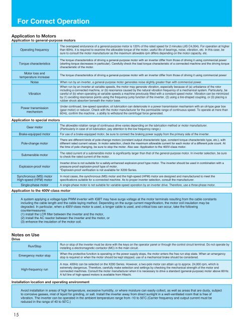
For Correct Operation<br />
Application to Motors<br />
Application to general-purpose motors<br />
Operating frequency<br />
The overspeed endurance of a general-purpose motor is 120% of the rated speed for 2 minutes (JIS C4,004). For operation at higher<br />
than 60Hz, it is required to examine the allowable torque of the motor, useful life of bearings, noise, vibration, etc. In this case, be<br />
sure to consult the motor manufacturer as the maximum allowable rpm differs depending on the motor capacity, etc.<br />
Torque characteristics<br />
Motor loss and<br />
temperature increase<br />
Noise<br />
Vibration<br />
Power transmission<br />
mechanism<br />
The torque characteristics of driving a general-purpose motor with an inverter differ from those of driving it using commercial power<br />
(starting torque decreases in particular). Carefully check the load torque characteristic of a connected machine and the driving torque<br />
characteristic of the motor.<br />
The torque characteristics of driving a general-purpose motor with an inverter differ from those of driving it using commercial power<br />
When run by an inverter, a general-purpose motor generates noise slightly greater than with commercial power.<br />
When run by an inverter at variable speeds, the motor may generate vibration, especially because of (a) unbalance of the rotor<br />
including a connected machine, or (b) resonance caused by the natural vibration frequency of a mechanical system. Particularly, be<br />
careful of (b) when operating at variable speeds a machine previously fitted with a constant speed motor. Vibration can be minimized<br />
by (1) avoiding resonance points using the frequency jump function of the inverter, (2) using a tire-shaped coupling, or (3) placing a<br />
rubber shock absorber beneath the motor base.<br />
Under continued, low-speed operation, oil lubrication can deteriorate in a power transmission mechanism with an oil-type gear box<br />
(gear motor) or reducer. Check with the motor manufacturer for the permissible range of continuous speed. To operate at more than<br />
60Hz, confirm the machine , s ability to withstand the centrifugal force generated.<br />
Application to special motors<br />
The allowable rotation range of continuous drive varies depending on the lubrication method or motor manufacturer.<br />
Gear motor<br />
(Particularly in case of oil lubrication, pay attention to the low frequency range.)<br />
Brake-equipped motor For use of a brake-equipped motor, be sure to connect the braking power supply from the primary side of the inverter.<br />
Pole-change motor<br />
There are different kinds of pole-change motors (constant output characteristic type, constant torque characteristic type, etc.), with<br />
different rated current values. In motor selection, check the maximum allowable current for each motor of a different pole count. At<br />
the time of pole changing, be sure to stop the motor. Also see: Application to the 400V-class motor.<br />
Submersible motor<br />
Explosion-proof motor<br />
The rated current of a submersible motor is significantly larger than that of the general-purpose motor. In inverter selection, be sure<br />
to check the rated current of the motor.<br />
Inverter drive is not suitable for a safety-enhanced explosion-proof type motor. The inverter should be used in combination with a<br />
pressure-proof explosion-proof type of motor.<br />
*Explosion-proof verification is not available for <strong>X200</strong> <strong>Series</strong>.<br />
Synchronous (MS) motor<br />
High-speed (HFM) motor<br />
Single-phase motor<br />
In most cases, the synchronous (MS) motor and the high-speed (HFM) motor are designed and manufactured to meet the<br />
specifications suitable for a connected machine. As to proper inverter selection, consult the manufacturer.<br />
A single-phase motor is not suitable for variable-speed operation by an inverter drive. Therefore, use a three-phase motor.<br />
Application to the 400V-class motor<br />
A system applying a voltage-type PWM inverter with IGBT may have surge voltage at the motor terminals resulting from the cable constants<br />
including the cable length and the cable laying method. Depending on the surge current magnification, the motor coil insulation may be<br />
degraded. In particular, when a 400V-class motor is used, a longer cable is used, and critical loss can occur, take the following<br />
countermeasures:<br />
(1) install the LCR filter between the inverter and the motor,<br />
(2) install the AC reactor between the inverter and the motor, or<br />
(3) enhance the insulation of the motor coil.<br />
Notes on Use<br />
<strong>Drive</strong><br />
Run/Stop<br />
Emergency motor stop<br />
High-frequency run<br />
Run or stop of the inverter must be done with the keys on the operator panel or through the control circuit terminal. Do not operate by<br />
installing a electromagnetic contactor (MC) in the main circuit.<br />
When the protective function is operating or the power supply stops, the motor enters the free run stop state. When an emergency<br />
stop is required or when the motor should be kept stopped, use of a mechanical brake should be considered.<br />
A max. 400Hz can be selected on the <strong>X200</strong> <strong>Series</strong>. However, a two-pole motor can attain up to approx. 24,000 rpm, which is<br />
extremely dangerous. Therefore, carefully make selection and settings by checking the mechanical strength of the motor and<br />
connected machines. Consult the motor manufacturer when it is necessary to drive a standard (general-purpose) motor above 60Hz.<br />
A full line of high-speed motors is available from Hitachi.<br />
Installation location and operating environment<br />
Avoid installation in areas of high temperature, excessive humidity, or where moisture can easily collect, as well as areas that are dusty, subject<br />
to corrosive gasses, mist of liquid for grinding, or salt. Install the inverter away from direct sunlight in a well-ventilated room that is free of<br />
vibration. The inverter can be operated in the ambient temperature range from -10 to 50˚C.(Carrier frequency and output current must be<br />
reduced in the range of 40 to 50˚C.)<br />
15


