SJ700 Series Brochure - Hitachi America, Ltd.
SJ700 Series Brochure - Hitachi America, Ltd.
SJ700 Series Brochure - Hitachi America, Ltd.
Create successful ePaper yourself
Turn your PDF publications into a flip-book with our unique Google optimized e-Paper software.
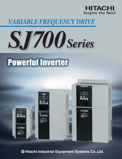
STANDARD SPECIFICATIONSModel Name Indication<strong>SJ700</strong>-055 HFEF2<strong>Series</strong> NameApplicable MotorCapacity004: 0.4kW(1/2HP)|4000: 400kW(500HP)Power SourceL : 3-phase 200V classH : 3-phase 400V classF : With keypadU : US versionE : European versionNote:Japanese versionF : Integrated EMC filterVersionModel ConfigurationApplicableMotorkW (HP)0.4(1/2)0.75(1)1.5(2)2.2(2)3.7(5)4.0(5)5.5(7.5)7.5(7.5)11(15)3-phase 200VAvailable3-phase 400VPlan modelLFUF2 LFF2 HFEF2 HFUF2 HFF215(20)18.5(25)22(30)30(40)37(50)45(60)55(75)75(100)90(125)110(150)132(175)150(200)185(250)315(400)400(550)6
SPECIFICATIONSGeneralSpecificationsControlInputsignalOutputsignalMonitoring on displayOther functionsProtective functionsEnvironmentalconditionsOptionsItemsControl methodOutput frequency range (*6)Frequency accuracyFrequency resolutionV/f characteristicsSpeed fluctuationAcceleration/deceleration timeStarting TorqueCarrier frequency rangeDC brakingFrequencysettingOperatorExternal signalExternal portOperatorForward /reverseExternal signalStart /stopExternal portTerminalsIntelligent input terminalsThermistor inputIntelligent output terminalsFunctionsTerminalsFunctionsMonitor output terminalsAmbient operating/storage temperature(*7)/ humidityLocationDigital input expansion cardFeedback expansion cardNetwork interface cardOthersGeneralSpecificationsLine to line sine wave pulse-width modulation (PWM) control0.1-400.0Hz(185kW and over:0.1-120Hz)Digital: ±0.01% of the maximum frequency, Analog: ±0.2%(25±10ûC)Digital setting: 0.01Hz, Analog setting: (Maximum frequency)/4,000 (O terminal: 12bit 0-10V, O2 terminal: 12bit -10-+10V)V/f optionally variable (30-400Hz of base frequency), V/f control (constant torque, reduced torque), Sensorless vector control±0.5% (sensorless vector control)0.01-3,600sec. (Linear/curve, accel./decel. selection), Two-stage accel./decel.200% at 0.3Hz (Sensorless vector control), 150% at around 0Hz (Sensorless vector control, 0Hz domain with motor one frame size down)0.5-15.0kHz(185kW and over:0.5-3.0kHz)Performs at start: under set frequency at deceleration, via an external input (braking force, time, and operating frequency).Up and Down keysDC 0-10V, -10-+10V (input impedance 10k½), 4-20mA (input impedance 100½)Setting via RS485 communicationStart/stop commands (forward/reverse switching by parameter setting)Forward-operation start/stop commands (reverse-operation start/stop possible when relevant commands are assigned to intelligent input terminals)3-wireinput possible (when relevant commands are assigned to control circuit terminals)Setting via RS485 communication8 terminals, NO/NC switchable, sink logic/source logic switchableReverse operation (RV), Multi-speed 1 setting (CF1), Multi-speed 2 setting (CF2), Multi-speed 3 setting (CF3), Multi-speed 4 setting (CF4), Jogging (JG),external DC braking (DB), 2nd motor control (SET), 2-stage acceleration/deceleration (2CH), free-run stop (FRS), external trip (EXT), unattended startprotection (USP), commercial power supply switching (CS), software lock (SFT), analog input switching (AT), 3rd motor control (SET3), reset (RS), startingby 3-wire input (STA), stopping by 3-wire input (STP), forward/reverse switching by 3-wire input (F/R), PID disable (PID), PID integration reset (PIDC),control gain switching (CAS), acceleration by remote control (UP), deceleration by remote control (DWN), data clearance by remote control (UDC), forcibleoperation (OPE), Multi-speed bit 1 (SF1), Multi-speed bit 2 (SF2), Multi-speed bit 3 (SF3), Multi-speed bit 4 (SF4), Multi-speed bit 5 (SF5), Multi-speed bit 6(SF6), Multi-speed bit 7 (SF7), overload restriction selection (OLR), torque limit selection (enabling/disabling) (TL), torque limit 1 (TRQ1), torque limit 2(TRQ2), P/PI switching (PPI), braking confirmation (BOK), orientation (ORT), LAD cancellation (LAC), clearance of position deviation (PCLR), permissionof 90ûshift phase (STAT), trigger for frequency addition (A145) (ADD), forcible-terminal operation (F-TM), permission of torque command input (ATR),cumulative power clearance (KHC), servo-on (SON), pre-excitation (FOC), general-purpose input 1 (MI1), general-purpose input 2 (MI2), general-purposeinput 3 (MI3), general-purpose input 4 (MI4), general-purpose input 5 (MI5), general-purpose input 6 (MI6), general-purpose input 7 (MI7), general-purposeinput 8 (MI8), analog command holding (AHD), no assignment (no)1 terminal (PTC characteristics)5 open-collector output terminals, NO/NC switchable, sink logic/source logic switchable 1 relay (1c-contact) output terminal: NO/NC switchableRunning (RUN), constant-speed reached (FA1), set frequency overreached (FA2), overload notice advance signal (1) (OL), output deviation for PID control(OD), alarm signal (AL), set frequency reached (FA3), over-torque (OTQ), instantaneous power failure (IP), undervoltage (UV), torque limited (TRQ),operation time over (RNT), plug-in time over (ONT), thermal alarm signal (THM), brake release (BRK), braking error (BER), 0 Hz detection signal (ZS),speed deviation maximum (DSE), positioning completed (POK), set frequency overreached 2 (FA4), set frequency reached 2 (FA5), overload noticeadvance signal (2) (OL2), PID feedback comparison (FBV), communication line disconnection (NDc), logical operation result 1 (LOG1), logical operationresult 2 (LOG2), logical operation result 3 (LOG3), logical operation result 4 (LOG4), logical operation result 5 (LOG5), logical operation result 6 (LOG6),capacitor life warning (WAC), cooling-fan speed drop (WAF), starting contact signal (FR), heat sink overheat warning (OHF), low-current indication signal(LOC), general-purpose output 1 (M01), general-purpose output 2 (M02), general-purpose output 3 (M03), general-purpose output 4 (M04), generalpurposeoutput 5 (M05), general-purpose output 6 (M06), inverter ready (IRDY), forward rotation (FWR), reverse rotation (RVR), major failure (MJA), alarmcode 0 to 3 (AC0 to AC3)Analog voltage output, analog current output, pulse-string output (e.g., A-F, D-F [n-fold, pulse output only], A, T, V, P)Output frequency, output current, output torque, frequency conversion data, trip history, input/output terminal status, electric power, and othersFree V/f setting (7 breakpoints), frequency upper/lower limit, jump (center) frequency, acceleration/deceleration according to characteristic curve, manualtorque boost level/breakpoint, energy-saving operation, analog meter adjustment, start frequency setting, carrier frequency adjustment, electronic thermalfunction (available also for free setting), external start/end frequency/frequency rate, analog input selection, retry after trip, restart after instantaneous powerfailure, output of various signals, starting with reduced voltage, overload restriction, initial-value setting, automatic deceleration at power failure, AVRfunction, fuzzy acceleration/deceleration, online/offline auto-tuning, high-torque multi-motor operation (sensorless vector control of two motors by oneinverter)Overcurrent protection, overvoltage protection, undervoltage protection, electronic thermal protection, temperature error protection, instantaneous powerfailure protection, phase loss input protection, braking-resistor overload protection, ground-fault current detection at power-on, USP error, external trip,emergency stop trip, CT error, communication error, option board error, and others-10-50ûC / -20-65ûC / 20-90%RH (No condensation)Altitude 1,000m or less, indoors (no corrosive gases or dust)SJ-DG (4digits BCD, 16bits binary)SJ-FB (vector control loop speed sensor)SJ-DN(DeviceNetTM), SJ-PBT(PROFIBUSR)EMI filters, input/output reactors, radio noize filters, braking resistors, braking units, LCR filter, communication cables*1: The protection method conforms to JEM 1030.*2: The applicable motor refers to <strong>Hitachi</strong> standard 3-phase motor (4-pole).To use other motors, be sure to prevent the rated motor current (50Hz) from exceeding the rated output current of the inverter.*3: The output voltage decreases as the main power supply voltage decreases except for the use of AVR function.*4: Braking resistor is not integrated in the inverter. Please install optional braking resistor or dynamic braking unit when large braking torque is required.*5: Conforms to the test method specified in JIS C0040(1999).*6: To operate the motor beyond 50/60Hz, please consult with the motor manufacturer about the maximum allowable rotation speed.*7: Storage temperature refers to the temperature in transportation.*8: Please be sure to connect DC reactor attached to 1850HF, 3150HF and 4000HF.7
DIMENSIONS<strong>SJ700</strong>-004037 LFUF2,LFF2<strong>SJ700</strong>-007037HFEF2, HFUF2, HFF2<strong>SJ700</strong>-055110 LFUF2,LFF2 /HFEF2, HFUF2,HFF2 <strong>SJ700</strong>-150220 LFUF2,LFF2 /HFEF2, HFUF2,HFF2 <strong>SJ700</strong>-300 LFUF2,LFF2 /HFEF2, HFUF2, HFF2<strong>SJ700</strong>-370450 LFUF2,LFF2<strong>SJ700</strong>-370550 HFEF2, HFUF2,HFF2 <strong>SJ700</strong>-550 LFUF2,LFF2 [Unit : mm(inch)]Inches for reference only.8
DIMENSIONS<strong>SJ700</strong>-750, HFEF2, HFUF2, HFF2 <strong>SJ700</strong>-1100HFF2 [Unit : mm(inch)]Inches for reference only.9
DIMENSIONS<strong>SJ700</strong>-1850HFEF2,HFUF2,HFF2Attachment DC reactor(DCL-H-185)3-15(0.59)2-M12 Eyebolts15(0.59)ExhaustDigital Operator170(6.69)200(7.87)200(7.87)4-1118(0.430.70)965(37.99)995(39.17)For M16300(11.81)Grounding TerminalM6MAX 270(10.62) MAX 240(9.44)P PDNPMAX 500(19.68)15(0.59)15(0.59)57.5(22.63) 290(11.41) 290(11.41) 57.5(2.26)Air Intake370(14.56)695(27.36)4-M12 Screw Holes For Eyebolts<strong>SJ700</strong>-3150HFEF2,HFUF2,HFF2Attachment DC reactor(DCL-H-315)3-15(0.59)2-M12 Eyebolts15(0.59)2-M12 Screw HolesExhaust325(12.79)285(11.22)4-10(0.39)Digital Operator285(11.22)325(12.79)NPGrounding TerminalM101270(50.0)1300(51.18)100(3.93) 100(3.93)50 50(1.96) (1.96)22-14(0.55)6(0.23)2-M10 Eyebolts41.5(1.63)PPD36(1.41)393(15.47)294(11.57)15(0.59)50(1.96) 290(11.41) 290(11.41) 50(1.96)680(26.77)15(0.59)450(17.71)Air IntakeGrounding TerminalM10430(16.92)max4-M12 Screw Holes For Eyebolts<strong>SJ700</strong>-4000HFEF2,HFUF2,HFF2Attachment DC reactor(DCL-H-400)4-15(0.59)2-M16 Eyebolts 2-M16 Screw HolesDigital Oprator75(2.95)15(0.59)300(11.81) 300(11.81) 300(11.81)1050(41.33)1670(65.74) 15(0.59)15(0.59) 1700(66.92)75(2.95)Exhaust450(17.71)Air Intake4-M16 Screw Holes For EyeboltsP325(12.79)285(11.22) 4-10(0.39)100(3.93) 100(3.93)50 50(1.96) (1.96)PD36(1.41)285(11.22)325(12.79)22-14(0.55)6(0.23)430(16.92)M10Grounding Terminal450(17.71)max2-M8 Eyebolts41.5(1.63)331(13.03)[Unit : mm(inch)]Inches for reference only.10
OPERATION and PROGRAMMING<strong>SJ700</strong> <strong>Series</strong> can be easily operated with the digital operator provided as standard. The digital operator can also be detached andcan be used for remote-control. Multilingual (English, French, German, Italian , Spanish and Portuguese) operator with copyfunction (SRW-0EX) and digital operator with potentiometer are also available as options.11Parameter DisplayDisplays frequency, motor current,rotational speed of the motor, andan alarm code.Monitor LEDsShows drive status.RUN key enable LEDLights up when the inverteris ready to respond to theRUN key.RUN KeyPress to run the motor.STOP/RESET KeyPress to stop the drive orreset an alarm.Function KeyPress to set or monitor aparameter value.Setting the output frequency1or the value previouslymonitored is displayed.Press2Function code appears.Pressuntil3appears.Power onFUNC key.appears.Press FUNC key.4Preset value is displayed.5Newly set value is displayed.6Returns to andthe setting is complete.Press to set desired value.Press STR keyto store the value.To run the motor, go back to monitormode or basic setting mode.The contents of a basic mode display.(default)If a desired parameter is not displayed, check thesetting of function "b037" (function code displayrestriction). To display all parameters, specify "00" for"b037".No.1234567891011121314151617181920212223242526272829Display coded001 to d104F001F002F003F004A001A002A003A004A005A020A021A022A023A044A045A085b001b002b008b011b037b083b084b130b131C021C022C036Power LEDLights when the power inputto the drive is ON.ALARM LEDLights to indicate that theinverter has tripped.Display Unit LEDsIndicates the unit associatedwith the parameter display.Store KeyPress to write the new valueto the EEPROM.Up/Down KeysPress up or down to sequencethrough parameters and functionsshown on the display, andincrement/decrement values.ItemMonitor displayOutput frequency settingAcceleration (1) time settingDeceleration (1) time settingOperation direction settingFrequency source settingRun command source settingBase frequency settingMaximum frequency setting[AT] selectionMulti-speed frequency settingMulti-speed 1 settingMulti-speed 2 settingMulti-speed 3 setting1st control methodV/f gain settingOperation mode selectionSelection of restart modeAllowable under-voltage power failure timeRetry-after-trip selectionRetry wait time after tripFunction code display restrictionCarrier frequency settingInitialization mode selectionSelection of overvoltage suppression functionSetting of overvoltage suppression levelSetting of intelligent output terminal 11Setting of intelligent output terminal 12Alarm relay active state
TERMINALSMAIN CIRCUIT TERMINALSTerminal DescriptionTerminal SymbolTerminal NameTerminal SymbolTerminal NameR(L1), S(L2), T(L3)Main power supply input terminalsP(+), N(-)External braking unit connection terminalsU(T1), V(T2), W(T3)Inverter output terminals(G)Ground connection terminalPD(+1), P(+)DC reactor connection terminalsR0(R0), T0(T0)Control power supply input terminalsP(+), RB(RB)External braking resistor connection terminalsScrewDiameter andTerminal WidthWW:Terminal widthModel Screwdiameter Terminal widthmm004~037LFUF2,LFF2/007~037HFEF2,HFUF2,HFF2055,075LFUF2,LFF2,HFEF2,HFUF2,HFF2110LFUF2,LFF2,HFEF2,HFUF2,HFF2150,185LFUF2,LFF2,150-300HFEF2,HFUF2,HFF2220,300LFUF2,LFF2370,450LFUF2,LFF2,370-550HFEF2,HFUF2,HFF2550LFUF2LF2,LFF2750,900HFEF2,HFUF2,HFF21100HFEF2/,HFUF2,HFF2/1320HFEF2,HFF2/1500HFUF21850HFEF2,HFUF2,HFF23150HFEF2,HFUF2,HFF24000HFEF2,HFUF2,HFF2R0T0 terminals (All models)M4M5M6M6M8M8M10M10M10M16M16M12M413181823 *12329 *2402940 *351 *345509*1 Ground Screw diameter is M6*2 Ground Screw diameter is M8*3 Ground Screw diameter is M12Terminal Arrangement004037LFUF2LFF2/007037HFEF2HFUF2HFF2R0T0R(L1)PD(+1)S(L2)P(+)T(L3)N(-)U(T1)V(T2)RB(RB (G)W(T3)(G)(G)R(L1)R0(R0)S(L2)T0(T0)T(L3)PD(+1)P(+)P(+)N(-)U(T1)V(T2)W(T3)(G)055-220LFUF2,LFF2,HFEF2,HFUF2,HFF2R(L1)(G)S(L2)T(L3)PD(+1)P(+)N(-)U(T1)RB(RBV(T2)W(T3)(G)R0(R0)T0(T0)(G)R(L1)R0(R0)S(L2)T0(T0)T(L3)P(+)PD(+1) P(+)N(-) U(T1)V(T2)W(T3)(G)300-370LFUF2,LFF2300-550HFEF2, HFUF2,HFF2(G)R(L1)S(L2)T(L3)PD(+1)P(+)N(-)U(T1)R0(R0)V(T2)T0(T0)W(T3)(G)(G)R(L1)R0(R0)S(L2)T0(T0)T(L3)PD(+1)P(+)P(+)N(-)U(T1)V(T2)W(T3)(G)450-550LFUF2,LFF2750-1100HFEF2,HFUF2,HFF21320HFEF2,HFF2/1500HFUF2R0(R0)T0(T0)R(L1)S(L2)T(L3)PD(+1)P(+)N(-)U(T1)V(T2)W(T3)(G)(G)12
TERMINALSCONTROL CIRCUIT TERMINALSTerminal DescriptionSymbol Name Explanation of Terminals RatingsPower SupplyLHCommon Terminal for AnalogPower SourcePower Source for FrequencySettingCommon terminal for H, O, O2, OI, AM, and AMI. Do not ground. -Power supply for frequency command inputDC 10V, 20mA max.OFrequency Command TerminalMaximum frequency is attained at DC 10V in DC 0-10V range. Set the voltage at A014 tocommand maximum frequency below DC 10V.Input impedance: 10k½, Allowableinput voltage range: DC -0.3-+12VAnalogFrequency SettingO2Frequency Command ExtraTerminalO2 signal is added to the frequency command of O or OI in DC 0-±10V range. Bychanging configuration, frequency command can be input also at O2 terminal.Input impedance:10k½, Allowableinput voltage range: DC 0-±12VOIFrequency Command TerminalMaximum frequency is attained at DC 20mA in DC 4-20mA range.When the intelligent terminal configured as AT is on, OI signal is enabled.Input impedance: 100½, Allowableinput voltage range: DC 0-24mAMonitor OutputAMAMIAnalog Output Monitor (Voltage)Analog Output Monitor (Current)Selection of one function from:Output frequency, output current, torque, output voltage, input power, electronic thermalload ratio, and LAD frequency.DC 0-10V, 2mA max.DC 4-20mA, 250½ max.Monitor OutputFMDigital Monitor (Voltage)[DC0-10V output (PWM output)] Selection of one function from: Output frequency, outputcurrent, torque, output voltage, input power, electronic thermal load ratio, and LAD frequency.[Digital pulse output (Pulse voltage DC 0/10V)] Outputs the value of output frequency asdigital pulse (duty 50%)Digital output frequencyrange: 0-3.6kHz, 1.2mA max.Power SupplyP24CM1Power Terminal for InterfaceCommon Terminal for InterfaceInternal power supply for input terminals. In the case of source type logic, common terminalfor contact input terminals.Common terminal for P24, TH, and FM. In the case of sink type logic, common terminal forcontact input terminals. Do not ground.DC 24V, 100mA max.-DigitalContactInputRunCommandFunctionsFW12345678Forward Command InputIntelligent Input TerminalsThe motor runs forward when FW terminal is ON,and stops when FW is OFF.Assign 8 functions to terminals.(Refer to the standard specifications for the functions.)[Input ON condition]Voltage between each terminaland PLC: DC 18V min.[Input OFF condition]Voltage between each terminaland PLC: DC 3V max.Input impedance between eachterminal and PLC: 4.7½CommonTerminalPLCCommon Terminal forIntelligent Input Terminals,Common Terminal forExternal Power Supply forPLCs, etc.Select sink or source logic with the short-circuit bar on the control terminals.Sink logic: Short P24 to PLC /Source logic: Short CM1 to PLC.When applying external power source, remove the short-circuit bar and connect PLC terminalto the external device.Allowable maximum voltagebetween each terminal andPLC: DC 27VOpenCollectorOutputState1112131415Intelligent Output TerminalsAssign 5 functions to open collector outputs.When the alarm code is selected at C062, terminal 11-13 or 11-14 are reserved for errorcodes of inverter trip.(Refer to the standard specifications for the functions.)Both sink and source logic are always applicable between each terminal and CM1.Decrease in voltage betweeneach terminal and CM2:4V max. during ONAllowable maximum voltage: DC 27VCM2Common Terminal forIntelligent Output TerminalsCommon terminal for intelligent output terminal 11-15.Allowable maximum current: 50mAAnalogAnalogInputSensorTHThermistor Input TerminalsThe inverter trips when the external thermistor detects abnormal temperature.Common terminal is CM1.[Recommended thermistor characteristics]Allowable rated power: 100mW or over.Impedance in the case of abnormal temperature: 3k½Note: Thermal protection level can be set between 0 and 9999½.Allowable input voltage range[Input Circuit]THThermistorCM1DC0-8VDC8V10k½1k½DigitalRelayOutputState/AlarmAL0AL1AL2Alarm Output TerminalsIn default setting, an alarm is activated when inverter output is turned off by a protectivefunction.Maximum capacity of relaysAL1-AL0:AC 250V, 2A(R load)/0.2A(L load)DC 30V, 8A(R load)/0.6A(L load)AL2-AL0:AC 250V, 1A(R load)/0.2A(L load)DC 30V, 1A(R load)/0.2A(L load)Minimum capacity of relaysAL1-AL0, AL2-AL0:AC100V, 10mA DC5V, 100mATerminal ArrangementLHOO2 AM FM TH FW 8OI AM1 P24 PLC CM1Screw diameter:M3CM1 5 37 6 4 2Terminal Width:6.4mm114 13 11 AL115 CM2 12 AL0 AL213
PROTECTIVE FUNCTION LIST FUNCTIONSMONITORINGFUNCTIONS and MAIN PROFILE PARAMETERSMonitor ModeSetting ModeExpanded FunctionA GROUP: STANDARD FUNCTIONSBasic settingsAnalog input and othersCoded001d002d003d004d005d006d007d008d009d010d012d013d014d015d016d017d018d019d022d023d024d025d026d027d028d029d030d080d081d086d090d102d103d104F001F002F202F302F003F203F303F004A---b---C---H---P---U----CodeA001A002A003A203A303A004A204A304A005A006A011A012Output frequency monitorOutput current monitorRotation direction minitoringProcess variable (PV), PID feedback monitorIntelligent input terminal statusIntelligent output terminal statusScaled output frequency monitoringActual-frequency monitoringTorque command monitoringTorque bias monitoringTorque monitoringOutput voltage monitoringPower monitoringCumulative power monitoringCumulative operation RUN time monitoringCumulative power-on time monitoringHeat sink temperature monitoringMotor temperature monitoringLife-check monitoringProgram counterProgram number monitoringUser monitor 0User monitor 1User monitor 2Pulse counterPosition setting monitorPosition feedback monitorTrip CounterTrip monitoring 1-6Programming error monitoringDC voltage monitoringBRD load factor monitoringElectronic thermal overload monitoringOutput frequency settingFunction NameAcceleration (1) time settingAcceleration (1) time setting, 2nd motorAcceleration (1) time setting, 3rd motorDeceleration (1) time settingDeceleration time setting, 2nd motorDeceleration time setting, 3rd motorKeypad Run key routingA Group: Standard functionsb Group: Fine tuning functionsC Group: Intelligent terminal functionsH Group: Motor constants functionsP Group: Expansion card functionsU Group: User-selectable menu functionsFrequency source settingRun command source settingBase frequency settingBase frequency setting, 2nd motorBase frequency setting, 3rd motorMaximum frequency settingMaximum frequency setting, 2nd motorMaximum frequency setting, 3rd motor[AT] selection[O2] selectionFunction NameO-L input active range start frequencyO-L input active range end frequency*1 This setting is valid only when the OPE-SR is connected.Monitored data or setting0.00 to 99.99, 100.0 to 400.0 (Hz)0.0 to 999.9, 1000 to 9999 (A)F (forward rotation), o (stopped), r (reverse rotation)0.00 to 99.99, 100.0 to 999.9, 1000. to 9999. 1000 to 9999 (10000 to 99990), 100 to 999 (10000 to 999000)FW8 7 6 54 3 2 1AL 15 14 13 12 11(Example) FW, 7, 2, 1:ON8, 6, 5, 4, 3 : OFF(Example) 12, 11 : ONAL, 15, 14, 13 :OFF0.00 to 99.99, 100.0 to 999.9, 1000. to 9999., 1000 to 3996 (10000 to 39960)-400. to -100., -99.9 to 0.00 to 99.99, 100.0 to 400.0 (Hz)-200. to +200. (%)-200. to +200. (%)-200. to +200. (%)0.0 to 600.0 (V)0.0 to 999.9 (kW)0.0 to 999.9, 1000. to 9999.1000 to 9999 (10000 to 99990), 100 to 999 (100000 to 999000)0. to 9999., 1000 to 9999 (10000 to 99990), 100 to 999 (10000 to 999000) (hr)0. to 9999., 1000 to 9999 (10000 to 99990), 100 to 999 (10000 to 999000) (hr)-020. to 200.0 ()-020. to 200.0 ()2 10to5120000 to 9999-2147483647 to 2147483647 (upper 4 digits including Ò-Ò)-2147483647 to 2147483647 (upper 4 digits including Ò-Ò)-2147483647 to 2147483647 (upper 4 digits including Ò-Ò)0to2147483647 (upper 4 digits)-1073741823 to 1073741823 (upper 4 digits including Ò-Ò)-1073741823 to 1073741823 (upper 4 digits including Ò-Ò)0. to 9999., 1000 to 6553 (10000 to 65530) (times)Factor, frequency (Hz), current (A), voltage across P-N (V),running time (hours), power-on time (hours)Warning code0.0 to 999.9 (V)0.0 to 100.0 (%)0.0 to 100.0 (%)0.0, "start frequency" to "maximum frequency" (or maximum frequency, 2nd/3rd motors) (Hz)0.0 to 100.0 (when PID function is enabled)0.01 to 99.99, 100.0 to 999.9, 1000. to 3600. (s)0.01 to 99.99, 100.0 to 999.9, 1000. to 3600. (s)0.01 to 99.99, 100.0 to 999.9, 1000. to 3600. (s)0.01 to 99.99, 100.0 to 999.9, 1000. to 3600. (s)0.01 to 99.99, 100.0 to 999.9, 1000. to 3600. (s)0.01 to 99.99, 100.0 to 999.9, 1000. to 3600. (s)00 (forward rotation), 01 (reverse rotation)01 (control circuit terminal block), 02 (digital operator), 03 (RS485), 04 (option 1), 05 (option 2)30. to "maximum frequency " (Hz)30. to "maximum frequency, 2nd motor" (Hz)30. to "maximum frequency, 3rd motor" (Hz)30. to 400. (Hz)30. to 400. (Hz)30. to 400. (Hz)0.00 to 99.99, 100.0 to 400.0 (Hz)0.00 to 99.99, 100.0 to 400.0 (Hz)ONOFFONOFFONOFFMonitored data or setting1: Capacitor on main circuit board2: Cooling-fan speed drop00 (keypad potentiometer) (*1), 01 (control circuit terminal block),02 (digital operator), 03 (RS485), 04 (option 1), 05 (option 2),06 (pulse-string input), 07 (easy sequence), 10 (operation function result)00 (switching between O and OI terminals), 01 (switching between O and O2 terminals),02 (switching between O terminal and keypad potentiometer) (*1), 03 (switching between OI terminaland keypad potentiometer) (*1), 04 (switching between O2 and keypad potentiometer) (*1)00 (single), 01 (auxiliary frequency input via O and OI terminals) (nonreversible),02 (auxiliary frequency input via O and OI terminals) (reversible), 03 (disabling O2 terminal)Default Setting-FE(CE) -FU(UL)--------------------------------= Allowed = Not permitted-F(JP)----0.00Hz 0.00Hz 0.00Hz30.00s30.00s30.00s30.00s30.00s30.00s00010150.50.50.50.50.50.00030.000.00---------------------------------30.00s30.00s30.00s30.00s30.00s30.00s00010160.60.60.60.60.60.00030.000.00-----------------------------30.00s30.00s30.00s30.00s30.00s30.00s00020260.60.60.60.60.60.00030.000.00Settingduring operation(allowed or not) Changeduring operation(allowed or not) = Allowed = Not permittedDefault Setting Setting Changeduring operation during operation-FE(CE) -FU(UL) -F(JP) (allowed or not) (allowed or not)14
Analog inputand othersMultispeed operation and JoggingV/f CharacteristicDC BrakingExternal frequencyadjustment Operation Mode and acceleration/deceleration function AVR PID ControlFrequency Upper/Lower Limit and Jump FrequencyCodeA013A014A015A016A017A019A020A220A320A021IA035A038A039A041A241A042A242A342A043A243A343A044A244A344A045A046A246A047A247A051A052A053A054A055A056A057A058A059A061A261A062A262A063A064A065A066A067A068A069A070A071A072A073A074A075A076A077A078A081A082A085A086A092A292A392A093A293A393A094A294A095A295A096A296A097A098A101A102A103A104Function NameMonitored data or settingDefault Setting-FE(CE) -FU(UL) -F(JP)O-L input active range start voltabeO-L input active range end voltabeO-L input active range start frequency selectionExternal frequency filter time constantEasy sequence function selectionMultispeed operation selectionMultispeed frequency settingMultispeed frequency setting, 2nd motorMultispeed frequency setting, 3rd motorMultispeed 1-15 settingJog frequency setting0. to "[O]-[L] input active range end voltage" (%)"[O]-[L] input active range start voltage" to 100. (%)00 (external start frequency), 01 (0 Hz)1. to 30. or 31. (500 ms filter ±0.1 Hz with hysteresis)00 (disabling), 01 (enabling)00 (binary: 16 speeds selectable with 4 terminals), 01 (bit: 8 speeds selectable with 7 terminals)0.0 or Òstart frequencyÓ to Òmaximum frequencyÓ (Hz)0.0 or Òstart frequencyÓ to Òmaximum frequency, 2nd motorÓ (Hz)0.0 or Òstart frequencyÓ to Òmaximum frequency, 3rd motorÓ (Hz)0.0 or Òstart frequencyÓ to Òn-th maximum frequencyÓ (Hz)"Start frequency" to 9.99 (Hz)00 (free-running after jogging stops [disabled during operation]), 01 (deceleration and stop after jogging0.100.0131.00000.000.000.000.001.000.100.0131.00000.000.000.000.001.000.100.0131.00000.000.000.000.001.00Jog stop modestops [disabled during operation]), 02 (DC braking after jogging stops [disabled during operation]),03 (free-running after jogging stops [enabled during operation]), 04 (deceleration and stop after joggingstops [enabled during operation]), 05 (DC braking after jogging stops [enabled during operation])00 00 00Torque boost method selectionTorque boost method selection, 2nd motorManual torque boost valueManual torque boost value, 2nd motorManual torque boost value, 3rd motorManual torque boost frequency adjustmentManual torque boost frequency adjustment, 2nd motorManual torque boost frequency adjustment, 3rd motorV/F characteristic curve selection, 1st motorV/F characteristic curve selection, 2nd motorV/F characteristic curve selection, 3rd motorV/f gain settingVoltage compensation gain setting for automatic torque boost. 1st motorVoltage compensation gain setting for automatic torque boost, 2nd motorSlippage compensation gain setting for automatic torque boost, 1st motorSlippage compensation gain setting for automatic torque boost, 2nd motorDC braking enableDC braking frequency settingDC braking wait timeDC braking force during decelerationDC braking time for decelerationDC braking/edge or level detection for [DB] inputDC braking force for startingDC braking time for startingDC braking carrier frequency settingFrequency upper limit settingFrequency upper limit setting, 2nd motorFrequency lower limit settingFrequency lower limit setting, 2nd motorJump (center) frequency setting 1Jump (hysteresis) frequency width setting 1Jump (center) frequency setting 2Jump (hysteresis) frequency width setting 2Jump (center) frequency setting 3Jump (hysteresis) frequency width setting 3Acceleration stop time frequency settingAcceleration stop time frequency settingPID function enablePID proportional gainPID integral time constantPID derivative gainPV scale conversion00(Manual torque boost) / 01(Automatic torque boost)00(Manual torque boost) / 01(Automatic torque boost)0.0 to 20.0 (%)0.0 to 20.0 (%)0.0 to 20.0 (%)0.0 to 50.0 (%)0.0 to 50.0 (%)0.0 to 50.0 (%)00 (VC), 01 (VP), 02 (free V/f), 03 (sensorless vector control), 04 (0Hz-range sensorless vector), 05 (vector with sensor)00 (VC), 01 (VP), 02 (free V/f), 03 (sensorless vector control), 04 (0Hz-range sensorless vector)00(VC), 01(VP)20. to 100. (%)0. to 255.0. to 255.0. to 255.0. to 255.00 (disabling), 01 (enabling), 02 (set frequency only)0.00 to 99.99, 100.0 to 400.0 (Hz)0.0 to 5.0 (s)0. to 100. (%)0.0 to 60.0 (s)00 (edge operation), 01 (level operation)0. to 100.(%)0.0 to 60.0(s)0.5 to 15.0(kHz)0.00 or "1st minimum frequency limit" to "maximum frequency" (Hz)0.00 or "2nd minimum frequency limit" to "maximum frequency, 2nd motor" (Hz)0.00 or "start frequency" to "maximum frequency limit" (Hz)0.00 or "start frequency" to "maximum frequency, 2nd motor limit" (Hz)0.00 to 99.99, 100.0 to 400.0 (Hz)0.00 to 10.00 (Hz)0.00 to 99.99, 100.0 to 400.0 (Hz)0.00 to 10.00 (Hz)0.00 to 99.99, 100.0 to 400.0 (Hz)0.00 to 10.00 (Hz)0.00 to 99.99, 100.0 to 400.0 (Hz)0.0 to 60.0 (s)00 (disabling), 01 (enabling), 02 (enabling inverted-data output)0.2 to 5.00.0 to 999.9, 1000. to 3600.0 (s)0.00 to 99.99, 100.0 (s)0.01 to 99.9900001.01.01.05.05.05.0000000100.100.100.100.100.000.500.000.0010.0.05.00.000.000.000.000.000.500.000.500.000.500.000.0001.01.00.001.0000001.01.01.05.05.05.0000000100.100.100.100.100.000.500.000.0010.0.05.00.000.000.000.000.000.500.000.500.000.500.000.0001.01.00.001.0000001.01.01.05.05.05.0000000100.100.100.100.100.000.500.000.0010.0.05.00.000.000.000.000.000.500.000.500.000.500.000.0001.01.00.001.00PV source settingOutput of inverted PID deviationPID variation rangeAVR function selectAVR voltage selectOperation mode selectionEnergy saving mode tuningAcceleration (2) time settingAcceleration (2) time setting, 2nd motorAcceleration (2) time setting, 3rd motorDeceleration (2) time settingDeceleration (2) time setting, 2nd motorDeceleration (2) time setting, 3rd motorSelect method to switch to Acc2/Dec2 profileSelect method to switch to Acc2/Dec2, 2nd motorAcc1 to Acc2 frequency transition pointAcc1 to Acc2 frequency transition point, 2nd motorDec1 to Dec2 frequency transition pointDec1 to Dec2 frequency transition point, 2nd motorAcceleration curve selectionDeceleration curve selectionOI-L input active range start frequencyOI-L input active range end frequencyOI-L input active range start currentOI-L input active range end current00 (input via OI), 01 (input via O), 02 (external communication),03 (pulse-string frequency input), 10 (operation result output)00(OFF), 01 (ON)0.0 to 100.0 (%)00 (always on), 01 (always off), 02 (off during deceleration)000.000000.000000.000200 V class: 200, 215, 220, 230, 240 (V) 400 V class: 380, 400, 415, 440, 460, 480 (V) 230/460 230/400 200/40000(Normal operation)/ 01(Energy-saving operation)/ 02(Fuzzy operation)0.1 to 100.00.01 to 99.99, 100.0 to 999.9, 1000. to 3600. (s)0.01 to 99.99, 100.0 to 999.9, 1000. to 3600. (s)0.01 to 99.99, 100.0 to 999.9, 1000. to 3600. (s)0.01 to 99.99, 100.0 to 999.9, 1000. to 3600. (s)0.01 to 99.99, 100.0 to 999.9, 1000. to 3600. (s)0.01 to 99.99, 100.0 to 999.9, 1000. to 3600. (s)00 (switching by 2CH terminal), 01 (switching by setting), 02 (switching only when rotation is reversed)00 (switching by 2CH terminal), 01 (switching by setting), 02 (switching only when rotation is reversed)0.00 to 99.99, 100.0 to 400.0 (Hz)0.00 to 99.99, 100.0 to 400.0 (Hz)0.00 to 99.99, 100.0 to 400.0 (Hz)0.00 to 99.99, 100.0 to 400.0 (Hz)00 (linear), 01 (S curve), 02 (U curve), 03 (inverted-U curve), 04 (EL-S curve)00 (linear), 01 (S curve), 02 (U curve), 03 (inverted-U curve), 04 (EL-S curve)0.00 to 99.99, 100.0 to 400.0 (Hz)0.00 to 99.99, 100.0 to 400.0 (Hz)0. to "[OI]-[L] input active range end current" (%)"[OI]-[L] input active range start current" to 100. (%)0050.015.0015.0015.0015.0015.0015.0000000.000.000.000.0000000.000.0020.100.0050.015.0015.0015.0015.0015.0015.0000000.000.000.000.0000000.000.0020.100.0050.015.0015.0015.0015.0015.0015.0000000.000.000.000.0000000.000.0020.100.0000= Allowed = Not permitted00Settingduring operation(allowed or not)Changeduring operation(allowed or not)15
Window comparatorOthersFree setting of V/f characteristicOthersCodeb056b060b061b062b063b064b065b066b067b068b070b071b072b078b079b082b083b084b085b086b087b088b089b090b091b092b095b096b098b099b100b101b102b103b104b105b106b107b108b109b110b111b112b113b120b121b122b123b124b125b126b127b130b131b132b133b134Function NameIntegral time setting for nonstop operation at power lossMaximum-limit level of window comparators OMinimum-limit level of window comparators OHysteresis width of window comparators OMaximum-limit level of window comparators OIMinimum-limit level of window comparators OIHysteresis width of window comparators OIMaximum-limit level of window comparators OIMinimum-limit level of window comparators O/OI/O2Hysteresis width of window comparators O/OI/O2Operation level at O disconnectionOperation level at OI disconnectionOperation level at O2 disconnectionCumulative input power data clearanceCumulative input power display gain settingStart frequency adjustmentCarrier frequency settingInitialization mode (parameters or trip history)Country code for initializationFrequency scaling conversion factorSTOP key enableRestart mode after FRSAutomatic carrier frequency reductionDynamic braking usage ratioStop mode selectionCooling fan controlDynamic braking controlDynamic braking activation levelThermistor for thermal protection controlThermal protection level settingFree-setting V/f frequency (1)Free-setting V/f voltage (1)Free-setting V/f frequency (2)Free-setting V/f voltage (2)Free-setting V/f frequency (3)Free-setting V/f voltage (3)Free-setting V/f frequency (4)Free-setting V/f voltage (4)Free-setting V/f frequency (5)Free-setting V/f voltage (5)Free-setting V/f frequency (6)Free-setting V/f voltage (6)Free-setting V/f frequency (7)Free-setting V/f voltage (7)Brake control enableBrake wait time for releaseBrake wait time for accelerationBrake wait time for stoppingBrake wait time for confirmationBrake release frequency settingBrake release current settingBraking frequencyOvervoltage suppression enableOvervoltage suppression levelAcceleration and deceleration rate at overvoltage suppressionOvervoltage suppression propotional gainOvervoltage suppression Integral time= Allowed = Not permittedMonitored data or settingDefault Setting Settingduring operation-FE(CE) -FU(UL) -F(JP) (allowed or not)0.0 to 9.999 /10.00 to 65.550. to 100. (lower limit : b061 + b062*2) (%)0. to 100. (lower limit : b060 - b062*2) (%)0. to 10. (lower limit : b061 - b062 / 2) (%)0. to 100. (lower limit : b064 + b066*2) (%)0. to 100. (lower limit : b063 - b066*2) (%)0. to 10. (lower limit : b063 - b064 / 2) (%)-100. to 100. (lower limit : b067 + b068*2) (%)-100. to 100. (lower limit : b066 - b068*2) (%)0. to 10. (lower limit : b066 - b067 / 2) (%)0.1001000010000100-10000.1001000010000100-10000.1001000010000100-10000to100 (%) or "no" (ignore)0to100 (%) or "no" (ignore)0to100 (%) or "no" (ignore)255(no) 255(no) 255(no)255(no) 255(no) 255(no)127(no) 127(no) 127(no)Clearance by setting "01" and pressing the STR key1. to 1000.0.10 to 9.99 (Hz)0.5 to 15.0 (kHz) (subject to derating)00 (clearing the trip history), 01 (initializing the data), 02 (clearing the trip history and initializing the data)00 (Japan), 01 (EU), 02 (U.S.A.)0.1 to 99.000 (enabling), 01 (disabling), 02 (disabling only the function to stop)00 (starting with 0 Hz), 01 (starting with matching frequency), 02 (starting with active matching frequency)00: invalid, 01: valid0.0 to 100.0 (%)00 (deceleration until stop), 01 (free-run stop)00 (always operating the fan), 01 (operating the fan only during inverter operation[including 5 minutes after power-on and power-off])00 (disabling), 01 (enabling [disabling while the motor is topped]), 02 (enabling [enabling also while the motor is topped])001.0.505.000011.00000000.0000000001.0.505.000011.00000000.0000000001.0.505.000011.00000000.0000000330 to 380, 660 to 760(V)360/720 360/720 360/720 00 (disabling the thermistor), 01 (enabling the thermistor with PTC), 02 (enabling the thermistor with NTC)0. to 9999. ()0. to "free-setting V/f frequency (2)" (Hz)0.0 to 800.0 (V)0. to "free-setting V/f frequency (3)" (Hz)0.0 to 800.0 (V)0. to "free-setting V/f frequency (4)" (Hz)0.0 to 800.0 (V)0. to "free-setting V/f frequency (5)" (Hz)0.0 to 800.0 (V)0. to "free-setting V/f frequency (6)" (Hz)0.0 to 800.0 (V)0. to "free-setting V/f frequency (7)" (Hz)0.0 to 800.0 (V)0.0 to 400.0 (Hz)0.0 to 800.0 (V)00 (disabling), 01 (enabling)0.00 to 5.00 (s)0.00 to 5.00 (s)0.00 to 5.00 (s)0.00 to 5.00 (s)0.00 to 99.99, 100.0 to 400.0 (Hz)003000.0.0.00.0.00.0.00.0.00.0.00.0.00.0.0000.000.000.000.000.00003000.0.0.00.0.00.0.00.0.00.0.00.0.00.0.0000.000.000.000.000.00003000.0.0.00.0.00.0.00.0.00.0.00.0.00.0.0000.000.000.000.000.000.0 to 2.00 x "rated current"Rated current of inverterx 1..0 0.00 to 99.99, 100.0 to 400.0 (Hz)00 (disabling the restraint), 01 (decelerating and stagnating), 02 (enabling acceleration)0.00000.00000.0000330 to 390 (V) (200 V class model), 660 to 780 (V) (400 V class model)380/760 380/760 380/760 0.10 to 30.00 (s)0.00 to 2.550.000 to 9.999 / 10.00 to 63.53 (s)1.000.500.0601.000.500.0601.000.500.060Changeduring operation(allowed or not)C GROUP: INTELLIGENT TERMINAL FUNCTIONSIntelligent input terminals17CodeC001C002C003C004C005C006C007C008Terminal [1] function (*2)Terminal [2] functionTerminal [3] function (*2)Terminal [4] functionTerminal [5] functionTerminal [6] functionTerminal [7] functionTerminal [8] functionFunction NameMonitored data or setting01 (RV: Reverse RUN), 02 (CF1: Multispeed 1 setting), 03 (CF2: Multispeed 2 setting),04 (CF3: Multispeed 3 setting), 05 (CF4: Multispeed 4 setting), 06 (JG: Jogging), 07 (DB:external DC braking), 08 (SET: Set 2nd motor data), 09 (2CH: 2-stageacceleration/deceleration), 11 (FRS: free-run stop), 12 (EXT: external trip), 13 (USP:unattended start protection), 14: (CS: commercial power source enable), 15 (SFT: softwarelock), 16 (AT: analog input voltage/current select), 17 (SET3: 3rd motor control), 18 (RS: reset),20 (STA: starting by 3-wire input), 21 (STP: stopping by 3-wire input), 22 (F/R: forward/reverseswitching by 3-wire input), 23 (PID: PID disable), 24 (PIDC: PID reset), 26 (CAS: control gainsetting), 27 (UP: remote control UP function), 28 (DWN: remote control DOWN function), 29(DWN: remote control data clearing), 31 (OPE: forcible operation), 32 (SF1: multispeed bit 1),33 (SF2: multispeed bit 2), 34 (SF3: multispeed bit 3), 35 (SF4: multispeed bit 4), 36 (SF5:multispeed bit 5), 37 (SF6: multispeed bit 6), 38 (SF7: multispeed bit 7), 39 (OLR: overloadrestriction selection), 40 (TL: torque limit enable), 41 (TRQ1: torque limit selection bit 1), 42(TRQ2: torque limit selection bit 2), 43 (PPI: P/PI mode selection), 44 (BOK: brakingconfirmation), 45 (ORT: orientation), 46 (LAC: LAD cancellation), 47 (PCLR: clearance ofposition deviation), 48 (STAT: pulse train position command input enable), 50 (ADD: trigger forfrequency addition [A145]), 51 (F-TM: forcible-terminal operation), 52 (ATR: permission oftorque command input), 53 (KHC: cumulative power clearance), 54 (SON: servo-on), 55 (FOC:pre-excitation), 56 (MI1: general-purpose input 1), 57 (MI2: general-purpose input 2), 58 (MI3:general-purpose input 3), 59 (MI4: general-purpose input 4), 60 (MI5: general-purpose input 5),61 (MI6: general-purpose input 6), 62 (MI7: general-purpose input 7), 63 (MI8: general-purposeinput 8), 65 (AHD: analog command holding), 66 (CP1: multistage position settings selection 1), 67 (CP2: multistage position settings selection 2), 68 (CP3: multistage position settingsselection 3), 69 (ORL: Zero-return limit function), 70 (ORG: Zero-return trigger function), 71(FOT: forward drive stop), 72 (ROT: reverse drive stop), 73 (SPD: speed / position switching),74 (PCNT: pulse counter), 75 (PCC: pulse counter clear), no (NO: no assignment)= Allowed = Not permittedDefault Setting Setting Changeduring operation during operation-FE(CE) -FU(UL) -F(JP) (allowed or not) (allowed or not)18(RS) 18(RS) 18(RS)*2 When the emergency stop function is enabled (SW1 = ON), "18" (RS) and "64" (EMR) are forcibly written to parameters "C001" and "C003",respectively. (You cannot arbitrarily write "64" to "C001".) If the SW1 signal is turned off and then turned on, "no" (no assignment) is set in parameter "C003".16(AT)06(JG)16(AT)06(JG)16(AT)06(JG)11(FRS) 11(FRS) 11(FRS)09(2CH) 09(2CH) 09(2CH)03(CF2) 13(USP) 03(CF2)02(CF1) 02(CF1) 02(CF1)01(RV) 01(RV) 01(RV)
Intelligentoutput terminals Analog monitoringIntelligent output terminals Intelligent input terminalsLevels and output terminal statusCommunication functionAdjustmentOthersMeteradjustmentCodeC011C012C013C014C015C016C017C018C019C021C022C023C024C025C026C027C028C029Terminal (1) active stateTerminal (2) active stateTerminal (3) active stateTerminal (4) active stateTerminal (5) active stateTerminal (6) active stateTerminal (7) active stateTerminal (8) active stateTerminal FW active stateTerminal (11) functionTerminal (12) functionTerminal (13) functionTerminal (14) functionTerminal (15) functionAlarm relay terminal functionFM signal selectionAM signal selectionAMI signal selectionFunction NameC030 Digital current monitor reference valueC031 Terminal (11) active stateC032 Terminal (12) active stateC033 Terminal (13) active stateC034 Terminal (14) active stateC035 Terminal (15) active stateC036 Alarm relay terminal active stateC038 Low-current indication signal output mode selectionC039 Low-current indication signal detection levelC040 Overload signal output modeC041 Overload level settingC042 Frequency arrival setting for accel.C043 Frequency arrival setting for decel.C044 PID deviation level settingC045 Frequency arrival setting for acceleration (2)C046 Frequency arrival setting for deceleration (2)C052 Maximum PID feedback dataC053 Minimum PID feedback dataC055 Over-torque(Forward-driving) level settingC056 Over-torque(Reverse-regenerating) level settingC057 Over-torque(Reverse-driving) level settingC058 Over-torque(Forward-regenerating) level settingC061 Electronic thermal warning level settingC062 Alarm code inputC063 Zero speed detection levelC064 Heat sink overheat warning levelC071 Communication speed selectionC072 Node allocationC073 Communication data length selectionC074 Communication parity selectionC075 Communication stop bit selectionC076 Selection of the operation after communication errorC077 Communication timeout limit before trippingC078 Communication wait timeC079 Communication mode selectionC081 O input span calibrationC082 OI input span calibrationC083 O2 input span calibrationC085 Thermistor input tuningC091 Debug mode enableC101 UP/DOWN memory mode selectionC102 Reset mode selectionC103 Restart mode after resetC105 FM gain adjustmentC106 AM gain adjustmentMonitored data or setting00(NO) / 01(NC)00(NO) / 01(NC)00(NO) / 01(NC)00(NO) / 01(NC)00(NO) / 01(NC)00(NO) / 01(NC)00(NO) / 01(NC)00(NO) / 01(NC)00(NO) / 01(NC)00 (RUN: running), 01 (FA1: constant-speed reached), 02 (FA2: set frequency overreached), 03 (OL:overload notice advance signal (1)), 04 (OD: output deviation for PID control), 05 (AL: alarm signal), 06(FA3: set frequency reached), 07 (OTQ: over-torque), 08 (IP: instantaneous power failure), 09 (UV:undervoltage), 10 (TRQ: torque limited), 11 (RNT: operation time over), 12 (ONT: plug-in time over), 13(THM: thermal alarm signal), 19 (BRK: brake release), 20 (BER: braking error), 21 (ZS: 0 Hz detectionsignal), 22 (DSE: speed deviation maximum), 23 (POK: positioning completed), 24 (FA4: set frequencyoverreached 2), 25 (FA5: set frequency reached 2), 26 (OL2: overload notice advance signal (2)), 27 (Odc:Analog O disconnection detection), 28 (OIDc: Analog OI disconnection detection), 29 (O2Dc: Analog O2disconnection detection), 31 (FBV: PID feedback comparison), 32 (NDc: communication line disconnection),33 (LOG1: logical operation result 1), 34 (LOG2: logical operation result 2), 35 (LOG3: logical operationresult 3), 36 (LOG4: logical operation result 4), 37 (LOG5: logical operation result 5), 38 (LOG6: logicaloperation result 6), 39 (WAC: capacitor life warning), 40 (WAF: cooling-fan speed drop), 41 (FR: startingcontact signal), 42 (OHF: heat sink overheat warning), 43 (LOC: low-current indication signal), 44 (M01:general-purpose output 1), 45 (M02: general-purpose output 2), 46 (M03: general-purpose output 3), 47(M04: general-purpose output 4), 48 (M05: general-purpose output 5), 49 (M06: general-purpose output 6),50 (IRDY: inverter ready), 51 (FWR: forward rotation), 52 (RVR: reverse rotation), 53 (MJA: major failure),54(WCO: window comparator O), 55(WCOI: window comparator OI), 56 (WCO2: window comparator O2)(When alarm code output is selected for "C062", functions "AC0" to "AC2" or "AC0" to "AC3" [ACn: alarmcode output] are forcibly assigned to intelligent output terminals 11 to 13 or 11 to 14, respectively.)00 (output frequency), 01 (output current), 02 (output torque), 03 (digital output frequency), 04 (outputvoltage), 05 (input power), 06 (electronic thermal overload), 07 (LAD frequency), 08 (digital currentmonitoring), 09 (motor temperature), 10 (heat sink temperature), 12 (general-purpose output YA0)00 (output frequency), 01 (output current), 02 (output torque), 04 (output voltage), 05 (input power), 06(electronic thermal overload), 07 (LAD frequency), 09 (motor temperature), 10 (heat sink temperature), 11(output torque [signed value]), 13 (general-purpose output YA1)00 (output frequency), 01 (output current), 02 (output torque), 04 (output voltage), 05 (input power), 06(electronic thermal overload), 07 (LAD frequency), 09 (motor temperature), 10 (heat sink temperature), 14(general-purpose output YA2)= Allowed = Not permittedDefault Setting Setting Changeduring operation during operation-FE(CE) -FU(UL) -F(JP) (allowed or not) (allowed or not)01(FA1) 01(FA1) 01(FA1)00(RUN) 00(RUN) 00(RUN)03(OL)07(OTO) 07(OTO) 07(OTO)40(WAF) 40(WAF) 40(WAF)05(AL)03(OL)05(AL)03(OL)05(AL)0.20 x "rated current" to 2.00 x "rated current" (A)(Current with digital current monitor output at 1,440 Hz)Rated current ofinverterx 1..000(NO) / 01(NC)00(NO) / 01(NC)00(NO) / 01(NC)00(NO) / 01(NC)00(NO) / 01(NC)00(NO) / 01(NC)00 (output during acceleration/deceleration and constant-speed operation),01 (output only during constant-speed operation)0000000000010100000000000101000000000001010.0 to 2.00 x "rated current" (A)Rated current of inverterx 1..000 (output during acceleration/deceleration and constant-speed operation),01 (output only during constant-speed operation)01 01 010.0 to 2.00 x "rated current" (A)Rated current of inverterx 1..00.00 to 99.99, 100.0 to 400.0 (Hz)0.00 to 99.99, 100.0 to 400.0 (Hz)0.0 to 100.0 (%)0.00 to 99.99, 100.0 to 400.0 (Hz)0.00 to 99.99, 100.0 to 400.0 (Hz)0.0 to 100.0 (%)0.0 to 100.0 (%)0. to 200. (%)0. to 200. (%)0. to 200. (%)0. to 200. (%)0. to 100. (%)00(Disabled) / 01(3-bit) / 02(4-bit)0.00 to 99.99, 100.0 (Hz)0. to 200.0 ()02 (loopback test), 03 (2,400 bps), 04 (4,800 bps), 05 (9,600 bps), 06 (19,200 bps)1. to 32.7(7bits), 8 (8 bits)00 (no parity), 01 (even parity), 02 (odd parity)1(1bit), 2 (2 bits)00 (tripping), 01 (tripping after decelerating and stopping the motor), 02 (ignoring errors),03 (stopping the motor after free-running), 04 (decelerating and stopping the motor)0.00 to 99.99 (s)0. to 1000. (ms)00(ASCII), 01(Modbus-RTU)0. to 9999., 1000 to 6553(10000 to 65530)0. to 9999., 1000 to 6553(1000065530)0.000.003.00.000.00100.00.0100.100.100.100.80.000,00120.041.7001020.000.000.000.003.00.000.00100.00.0100.100.100.100.80.000,00120.041.7001020.000.000.000.003.00.000.00100.00.0100.100.100.100.80.000,00120.041.7001020.000.000. to 9999., 1000 to 6553(1000065530)Factory set0.0 to 999.9, 1000.(Do not change this parameter, which is intended for factory adjustment.)00 (not storing the frequency data), 01 (storing the frequency data)00000000000000 (resetting the trip when RS is on), 01 (resetting the trip when RS is off), 00 00 0002 (enabling resetting only upon tripping [resetting when RS is on])00 (starting with 0 Hz), 01 (starting with matching frequency), 02 (restarting with active matching frequency)50. to 200. (%)50. to 200. (%)00100.100.00100.100.00100.100.00000000000000000000000000000000000100000000000000000000000000000000000018
MeteradjustmentTerminalAdjustmentOutput terminal operation functionInput terminal responseotherCodeC107C109C110C111C121C122C123C130C131C132C133C134C135C136C137C138C139C140C141C142C143C144C145C146C147C148C149C150C151C152C153C154C155C156C157C158C159C160C161C162C163C164C165C166C167C168C169Function NameAMI gain adjustmentAM bias adjustmentAMI bias adjustmentOverload setting (2)O input zero calibrationOI input zero calibrationO2 input zero calibrationOutput 11 on-delay timeOutput 11 off-delay timeOutput 12 on-delay timeOutput 12 off-delay timeOutput 13 on-delay timeOutput 13 off-delay timeOutput 14 on-delay timeOutput 14 off-delay timeOutput 15 on-delay timeOutput 15 off-delay timeOutput RY on-delay timeOutput RY off-delay timeLogical output signal 1 selection 1Logical output signal 1 selection 2Logical output signal 1 operator selectionLogical output signal 2 selection 1Logical output signal 2 selection 2Logical output signal 2 operator selectionLogical output signal 3 selection 1Logical output signal 3 selection 2Logical output signal 3 operator selectionLogical output signal 4 selection 1Logical output signal 4 selection 2Logical output signal 4 operator selectionLogical output signal 5 selection 1Logical output signal 5 selection 2Logical output signal 5 operator selectionLogical output signal 6 selection 1Logical output signal 6 selection 2Logical output signal 6 operator selectionInput terminal response time setting 1Input terminal response time setting 2Input terminal response time setting 3Input terminal response time setting 4Input terminal response time setting 5Input terminal response time setting 6Input terminal response time setting 7Input terminal response time setting 8Input terminal response time setting FWMultistage speed/position determination timeMonitored data or setting50. to 200. (%)0. to 100. (%)0. to 100. (%)0.0 to 2.00 x "rated current" (A)0. to 9999., 1000 to 6553 (10000 to 65530)0. to 9999., 1000 to 6553 (10000 to 65530)0. to 9999., 1000 to 6553 (10000 to 65530)0.0 to 100.0 (s)0.0 to 100.0 (s)0.0 to 100.0 (s)0.0 to 100.0 (s)0.0 to 100.0 (s)0.0 to 100.0 (s)0.0 to 100.0 (s)0.0 to 100.0 (s)0.0 to 100.0 (s)0.0 to 100.0 (s)0.0 to 100.0 (s)0.0 to 100.0 (s)Same as the settings of C021 to C026 (except those of LOG1 to LOG6)Same as the settings of C021 to C026 (except those of LOG1 to LOG6)00 (AND), 01 (OR), 02 (XOR)Same as the settings of C021 to C026 (except those of LOG1 to LOG6)Same as the settings of C021 to C026 (except those of LOG1 to LOG6)00 (AND), 01 (OR), 02 (XOR)Same as the settings of C021 to C026 (except those of LOG1 to LOG6)Same as the settings of C021 to C026 (except those of LOG1 to LOG6)00 (AND), 01 (OR), 02 (XOR)Same as the settings of C021 to C026 (except those of LOG1 to LOG6)Same as the settings of C021 to C026 (except those of LOG1 to LOG6)00 (AND), 01 (OR), 02 (XOR)Same as the settings of C021 to C026 (except those of LOG1 to LOG6)Same as the settings of C021 to C026 (except those of LOG1 to LOG6)00 (AND), 01 (OR), 02 (XOR)Same as the settings of C021 to C026 (except those of LOG1 to LOG6)Same as the settings of C021 to C026 (except those of LOG1 to LOG6)00 (AND), 01 (OR), 02 (XOR)0. to200.(2ms)0. to200.(2ms)0. to200.(2ms)0. to200.(2ms)0. to200.(2ms)0. to200.(2ms)0. to200.(2ms)0. to200.(2ms)0. to200.(2ms)0. to200.(10ms)= Allowed = Not permittedDefault Setting Setting Changeduring operation during operation-FE(CE) -FU(UL) -F(JP) (allowed or not) (allowed or not)100.0.20.0.00.00.00.00.00.00.00.00.00.00.00.00000000000000000000000000000000000001111111110100.0.20.Rated current ofinverterx 1..0Factory set0.00.00.00.00.00.00.00.00.00.00.00.00000000000000000000000000000000000001111111110100.0.20.0.00.00.00.00.00.00.00.00.00.00.00.00000000000000000000000000000000000001111111110H GROUP: MOTOR CONSTANTS FUNCTIONSCodeH001H002H202H003H203H004H204H005H205H006H206H306H020H220H021H221H022H222H023H223H024H224H030H230H031H231H032H232H033H233Control constants19Function NameAuto-tuning SettingMotor data selection, 1st motorMotor data selection, 2nd motorMotor capacity, 1st motorMotor capacity, 2nd motorMotor poles setting, 1st motorMotor poles setting, 2nd motorMotor speed constant, 1st motorMotor speed constant, 2nd motorMotor stabilization constant, 1st motorMotor stabilization constant, 2nd motorMotor stabilization constant, 3rd motorMotor constant R1, 1st motorMotor constant R1, 2nd motorMotor constant R2, 1st motorMotor constant R2, 2nd motorMotor constant L, 1st motorMotor constant L, 2nd motorMotor constant IoMotor constant Io, 2nd motorMotor constant JMotor constant J, 2nd motorAuto constant R1, 1st motorAuto constant R1, 2nd motorAuto constant R2, 1st motorAuto constant R2, 2nd motorAuto constant L, 1st motorAuto constant L, 2nd motorAuto constant Io, 1st motorAuto constant Io, 2nd motorMonitored data or setting00 (disabling auto-tuning), 01 (auto-tuning without rotation), 02 (auto-tuning with rotation)00 (<strong>Hitachi</strong> standard data), 01 (auto-tuned data), 02 (auto-tuned data [with online auto-tuning function])00 (<strong>Hitachi</strong> standard data), 01 (auto-tuned data), 02 (auto-tuned data [with online auto-tuning function])0.20 to 400.0 (kW)0.20 to 400.0 (kW)2, 4, 6, 8, 10(poles)2, 4, 6, 8, 10(poles)0.001 to 9.999, 10.00 to 80.00 (10.000 to 80.000)0.001 to 9.999, 10.00 to 80.00 (10.000 to 80.000)0. to 255.0. to 255.0. to 255.0.001 to 9.999, 10.00 to 65.53 ()0.001 to 9.999, 10.00 to 65.53 ()0.001 to 9.999, 10.00 to 65.53 ()0.001 to 9.999, 10.00 to 65.53 ()0.01 to 99.99, 100.0 to 655.3 (mH)0.01 to 99.99, 100.0 to 655.3 (mH)0.01 to 99.99, 100.0 to 655.3 (A)0.01 to 99.99, 100.0 to 655.3 (A)0.001 to 9.999, 10.00 to 99.99, 100.0 to 999.9, 1000. to 9999.0.001 to 9.999, 10.00 to 99.99, 100.0 to 999.9, 1000. to 9999.0.001 to 9.999, 10.00 to 65.53 ()0.001 to 9.999, 10.00 to 65.53 ()0.001 to 9.999, 10.00 to 65.53 ()0.001 to 9.999, 10.00 to 65.53 ()0.01 to 99.99, 100.0 to 655.3 (mH)0.01 to 99.99, 100.0 to 655.3 (mH)0.01 to 99.99, 100.0 to 655.3 (A)0.01 to 99.99, 100.0 to 655.3 (A)= Allowed = Not permittedDefault Setting Setting Changeduring operation during operation-FE(CE) -FU(UL) -F(JP) (allowed or not) (allowed or not)000000441,5901,590100.100.100.000000Factory set441,5901,590100.100.100.Depending onmotor capacity000000441,5901,590100.100.100.
Controlconstantssequence Absolute position controlOutput terminal operation functionControl constantsCodeH034H234H050H250H051H251H052H252H060H260H061H261H070H071H072H073P001P002P011P012P013P014P015P016P017P018P019P020P021P022P023P024P025P026P027P028P029P031P032P033P034P035P036P037P038P039P040P044P045P046P047P048P049P055P056P057P058P060IP067P068P069P070P071P072P073P074P100IP131Function NameAuto constant J, 1st motorAuto constant J, 2nd motorPI proportional gain for 1st motorPI proportional gain for 2nd motorPI integral gain for 1st motorPI integral gain for 2nd motorP proportional gain setting for 1st motorP proportional gain setting for 2nd motorZero LV lmit for 1st motorZero LV lmit for 2nd motorZero LV starting boost current for 1st motorZero LV starting boost current for 2nd motorTerminal selection PI proportional gain settingTerminal selection PI integral gain settingTerminal selection P proportional gain settingGain switching timeP GROUP: EXPANSION CARD FUNCTIONSCodeFunction NameOperation mode on expansion card 1 errorOperation mode on expansion card 2 errorEncoder pulse-per-revolution (PPR) settingControl pulse settingPulse input mode settingHome search stop position settingHome search speed settingHome search direction settingHome search completion range settingHome search completion delay time settingElectronic gear set position selectionElectronic gear ratio numerator settingElectronic gear ratio denominator settingFeed-forward gain settingPosition loop gain settingPosition bias settingTemperature compensation thermistor enableOver-speed error detection level settingSpeed deviation error detection level settingNumerator of motor gear ratioDenominator of motor gear ratioAccel./decel. time input selectionPositioning command input selectionTorque command input selectionTorque command settingPolarity selection at the torque command input via O2 terminalTorque bias modeTorque bias valueTorque bias polarity selectionSpeed limit for torque-controlled operation (forward rotation)Speed limit for torque-controlled operation (reverse rotation)DeviceNet comm watchdog timerInverter action on DeviceNet comm errorDeviceNet polled I/O : Output instance numberDeviceNet polled I/O : input instance numberInverter action on DeviceNet idle modeDeviceNet motor poles setting for RPMPulse-string frequency scaleTime constant of pulse-string frequency filterPulse-string frequency biasPulse-string frequency limitMultistage position setting 0-7Zero-return mode selectionZero-return direction selectionLow-speed zero-return frequencyHigh-speed zero-return frequencyPosition range specification (forward)Position range specification (reverse)Teaching selectionEasy sequence user parameter U (00)-(31)Monitored data or setting0.001 to 9.999, 10.00 to 99.99, 100.0 to 999.9, 1000. to 9999.0.001 to 9.999, 10.00 to 99.99, 100.0 to 999.9, 1000. to 9999.0.0 to 999.9, 1000.0.0 to 999.9, 1000.0.0 to 999.9, 1000.0.0 to 999.9, 1000.0.01 to 10.000.01 to 10.000.0 to 100.00.0 to 100.00. to50.(%)0. to50.(%)0.0 to 999.9, 1000.0.0 to 999.9, 1000.0.00 to 10.000. to 9999. (ms)Monitored data or setting00 (tripping), 01 (continuing operation)00 (tripping), 01 (continuing operation)128. to 9999., 1000 to 6500 (10000 to 65000) (pulses)00 (ASR), 01 (APR), 02 (APR2), 03 (HAPR)00 (mode 0), 01 (mode 1), 02 (mode 2)0. to 4095."start frequency" to "maximum frequency" (up to 120.0) (Hz)00 (forward), 01 (reverse)0. to 9999., 1000 (10000) (pulses)0.00 to 9.99 (s)00 (feedback side), 01 (commanding side)0. to 9999.0. to 9999.0.00 to 99.99, 100.0 to 655.30.00 to 99.99, 100.0-204 (-2048.) / -999. to 204800 (no compensation), 01 (compensation)0.0 to 150.0 (%)0.00 to 99.99, 100.0 to120.0 (Hz)0. to 9999.0. to 9999.00 (digital operator), 01 (option 1), 02 (option 2), 03 (easy sequence)00 (digital operator), 01 (option 1), 02 (option 2)00 (O terminal), 01 (OI terminal), 02 (O2 terminal), 03 (digital operator)0. to 200. (%)00 (as indicated by the sign), 01 (depending on the operation direction)00 (disabling the mode), 01 (digital operator), 02 (input via O2 terminal)-200. to +200. (%)00 (as indicated by the sign), 01 (depending on the operation direction)0.00 to "maximum frequency" (Hz)0.00 to "maximum frequency" (Hz)0.00 to 99.99 (s)00 (tripping), 01 (tripping after decelerating and stopping the motor), 02 (ignoring errors),03 (stopping the motor after free-running), 04 (decelerating and stopping the motor)20, 21, 10070, 71, 10100 (tripping), 01 (tripping after decelerating and stopping the motor), 02 (ignoring errors),03 (stopping the motor after free-running), 04 (decelerating and stopping the motor)0, 2, 4, 6, 8, 10, 12, 14, 16, 18, 20, 22, 24, 26, 28, 30, 32, 34, 36, 38 (poles)1.0to 50.0(kHz)0.01 to 2.00 (s)-100. to +100. (%)0. to 100. (%)Position setting range reverse side Ð forward side(upper 4 digits including Ò-Ò)00(Low) / 01 (Hi1) / 00 (Hi2)00 (FW) / 01 (RV)0.00 Ð 10.00 (Hz)0.00 Ð 99.99 / 100.0 Ð Maximum frequency setting, 1st motor (Hz)0 Ð 268435455 (when P012 = 02)0 Ð1073741823 (When P012 = 03) (upper 4 digits)-268435455 Ð 0 (when P012 = 02)-1073741823 - 0 (When P012 = 03) (upper 4 digits)00 (X00) / 01 (X01) / 02 (X02) / 03 (X03) /04 (X04) / 05 (X05) / 06 (X06) / 07 (X07)0. to 9999., 1000 to 6553 (10000 to 65535)Default Setting-FE(CE) -FU(UL) -F(JP)Depending on motor capacity = Allowed = Not permittedSettingduring operation(allowed or not)Changeduring operation(allowed or not)= Allowed = Not permittedDefault Setting Setting Changeduring operation during operation-FE(CE) -FU(UL) -F(JP) (allowed or not) (allowed or not)0000102400000.5.00005.0.00001.1.0.000.500.00135.07.501.1.0000000.00000.000.000.001.00012171010025.00.100.100.000000.000.0000 0.0000102400000.5.00005.0.00001.1.0.000.500.00135.07.501.1.0000000.00000.000.000.001.00012171010025.00.100.100.000000.000.00268435455-26843545500 0.0000102400000.5.00005.0.00001.1.0.000.500.00135.07.501.1.0000000.00000.000.000.001.00012171010025.00.100.100.000000.000.0000 0. U GROUP: USER-SELECTABLE MENU FUNCTIONSparametersCodeU001IP012Function NameUser selected functions 1-12no/d001 to P131Monitored data or setting= Allowed = Not permittedDefault Setting Setting Changeduring operation during operation-FE(CE) -FU(UL) -F(JP) (allowed or not) (allowed or not)no no no 20
PROTECTIVE FUNCTIONSNameOver-current protectionOverload protection(*1)Braking resistoroverload protectionOver-voltage protectionEEPROM error(*2)Under-voltage errorCT(Current transformer) errorCPU errorExternal tripUSP errorGround faultInput over-voltage protectionInstantaneous power failureTemperature error due to lowcooling-fan speedInverter thermal tripGate array errorPhase loss detectionMain circuit error (*3)IGBT errorThermistor errorBraking errorEmergency stop (*4)Low-speed overload protectionModbus communication errorOut of operation dueto under-voltageEasy sequence function ErrorExpansion card 1 connection errorExpansion card 2 connection errorCause(s)The inverter output was short-circuited, or the motor shaft is locked or has aheavy load. These conditions cause excessive current for the inverter, so theinverter output is turned off.Communication error has occurred between CPU and gate array.One of three lines of 3-phase power supply is missing.An error has been detected in an expansion card or at its connecting terminals.While at constant speedDuring decelerationDuring accelerationOthersWhen a motor overload is detected by the electronic thermal function, the inverter trips and turns off its output.When the regenerative braking resistor exceeds the usage time allowance or an over-voltage caused by thestop of the BRD function is detected, the inverter trips and turns off its output.When the DC bus voltage exceeds a threshold, due to regenerative energy from the motor, the inverter tripsand turns off its output.When the built-in EEPROM memory has problems due to noise or excessive temperature, the inverter tripsand turns off its output.A decrease of internal DC bus voltage below a threshold results in a control circuit fault. This condition canalso generate excessive motor heat or cause low torque. The inverter trips and turns off its output.If a strong source of electrical interference is close to the inverter or abnormal operations occur in thebuilt-in CT, the inverter trips and turns off its output.When a malfunction in the built-in CPU has occurred, the inverter trips and turns off its output.When a signal to an intelligent input terminal configured as EXT has occurred, the inverter trips and turnsoff its output.An error occurs when power is cycled while the inverter is in RUN mode if the Unattended Start Protection(USP) is enabled. The inverter trips and does not go into RUN mode until the error is cleared.The inverter is protected by the detection of ground faults between the inverter output and the motor duringpower-up tests. This feature protects the inverter only.When the input voltage is higher than the specified value, it is detected 60 seconds after power-up and theinverter trips and turns of its output.When power is cut for more than 15ms, the inverter trips and turns off its output. If power failure continues,the error will be cleared. The inverter restarts if it is in RUN mode when power is cycled.The inverter will display the error code shown on the right if the lowering of cooling-fan speed is detected atthe occurrence of the temperature error described below.When the inverter internal temperature is higher than the specified value, the thermal sensor in the invertermodule detects the higher temperature of the power devices and trips, turning off the inverter output.The inverter will trip if the gate array cannot confirm the on/off state of IGBT because of a malfunction dueto noise or damage to the main circuit element.When an instantaneous over-current has occurred, the inverter trips and turns off its output to protect maincircuit element.When the thermistor inside the motor detects temperature higher than the specified value, the inverter tripsand turns off its output.The inverter turns off its output when it can not detect whether the braking is ON or OFF within waiting timeset at b024 after it has released the brake. (When braking is enabled at b120)If the EMR signal (on three terminals) is turned on when the slide switch (SW1) on the logic board is set toON, the inverter hardware will shut off the inverter output and display the error code shown on the right.If overload occurs during the motor operation at a very low speed at 0.2 Hz or less, the electronic thermal protectioncircuit in the inverter will detect the overload and shut off the inverter output. (2nd electronic thermal control)(Note that a high frequency may be recorded as the error history data.)If timeout occurs because of line disconnection during the communication in Modbus-RTU mode, the inverterwill display the error code shown on the right. (The inverter will trip according to the setting of "C076".)Due to insufficient voltage, the inverter has turned off its output and been trying torestart. If it fails to restart, it goes into the under-voltage error.Error indications by protective functions with the easy sequence function used.*1: Reset operation is acceptable 10 seconds after the trip.*2: Check the parameters when EEPROM error occurs.*3: The inverter will not accept reset commands input via the RS terminal or entered by the STOP/RESET key. Therefore, turn off the inverter power.*4: The inverter will not accept the reset command entered from the digital operator. Therefore, reset the inverter by turning on the RS terminal.Displayon digitaloperatorDisplay on remoteoperator/copy unitERR1****OC.DriveOC.DecelOC.AccelOver.COver.LOL.BRDOver.VEEPROMUnder.VCTCPUEXTERNALUSPGND.Flt.OV.SRCInst.P-FOH.stFANOH FINGAPH.FailMain.CirIGBTTHBRAKEEMROL-LowSPNET.ERRUV.WAITPRG.CMDPRG.NSTPRG.ERR1OP1-0 OP1-9OP2-0 OP2-9Status DisplayCode Description0Reset1StopCode23DescriptionDecelerationConstant SpeedCode45DescriptionAccelerationf0 StopCode67DescriptionStartingDBCode89DescriptionOverload RestrictionForcible or servo-onHow to access the details about the present fault21Error codeStatus at trip pointOutput frequencyat trip pointMotor currentat trip pointVoltage betweenP(+) and N() attrip pointCumulative inverterRUN time at trip pointCumulative power-ontime at trip point
CONNECTING DIAGRAMSource type logicIn case of 400V class, place a transformer for operating circuit to receive 200V.200V-240V+10%, -15%50/60Hz±5%(*2)Remove connection with J51when RoTo power is suppliedexternallyControl power sourceRR(L1)S(L2)T(L3)T(J51)R0T0(*2)<strong>SJ700</strong>(T1)U(T2)V(T3)W(+1)PD(+) PIMDC link choke(Note1)Dynamic braking unit (BRD)Short-circuitbarP24PLCCM1RB(-) NPNRBR1R2AL1AL2AL1AL2RBPRBPForward commandFWFor 30kW(40HP) and overIntelligent inputterminals (8 terminals)FM monitor output(PWM)Frequencysetting device500-2k½DC0-10V- +ThermistorDC0-10V(12bit)DC-10-+10V(12bit)DC4-20mA(12bit)8761FMCM1THHOO2OIL100½10k½10k½DC10VDC24VAL0AL1AL2SPSNRPSNIntelligent relayoutput contacts(default:alarm output)*11511CM2(Inverter)PIntelligent output terminals(5 terminals)For up to 22kW(30HP)PRB RBNBraking resistor(RB)RS-485Serial communication port(To operating circuit)The alarm relay contacts ALO and AL2when it is in Trip Mode or when inputPower is OFF,by factory default setting.*1( )AM monitor output(Analog output)AM monitor output(Analog output)DC0-10V(10bit)DC4-20mA(10bit)AMAMI(G)Expansion card 1Expansion card 2OptionTerminal NameCommon terminalFW, 1, 2, 3, 4, 5, 6, 7, 8 FM, TH H, O, O2, OI, AM, AMIP24CM1LCustomer wiring(Outside the inverter)Note1:Please be sure to connect DC reactor attached to 1850HF, 3150HF and 4000HF.22
CONNECTING DIAGRAMSink type logicIn case of 400V class, place a transformer for operating circuit to receive 200V.200V-240V+10%, -15%50/60Hz±5%(*2)Remove connection with J51when RoTo power is suppliedexternallyControl power sourceRR(L1)S(L2)T(L3)T(J51)R0T0(*2)<strong>SJ700</strong>(T1)U(T2)V(T3)W(+1)PD(+) PIMDC link choke(Note 1)Dynamic braking unit (BRD)Short-circuit barP24PLCRB(-) NPNRBR1R2AL1AL2AL1AL2RBPRBPForward commandIntelligent inputterminals(8 terminals)FM monitor output(PWM)Frequencysetting device500-2k½DC0-10V- +ThermistorDC0-10V(12bit)DC-10-+10V(12bit)DC4-20mA(12bit)FW8761FMCM1THHOO2OIL100½10k½10k½DC10VDC24VAL0AL1AL2SPSNRPSNFor 30kW(40HP) and overIntelligent relayoutput contacts(default:alarm output)*11511CM2For up to 22kW(30HP)(Inverter)PNPRB RBBraking resistor(RB)(To operating circuit)The alarm relay contacts ALO and AL2when it is in Trip Mode or when inputPower is OFF,by factory default setting.*1( )Intelligent output terminals(5 terminals)RS-485Serial communication portAM monitor output(Analog output)AM monitor output(Analog output)DC0-10V(10bit)DC4-20mA(10bit)AMAMI(G)Expansion card 1Expansion card 2OptionTerminal NameCommon terminalFW, 1, 2, 3, 4, 5, 6, 7, 8, FM, THCM1H, O, O2, OI, AM, AMILCustomer wiring(Outside the inverter)Note1:Please be sure to connect DC reactor attached to 1850HF, 3150HF and 4000HF.23
CONNECTING TO PLCCONNECTION WITH INPUT TERMINALS1. USING INTERNAL POWER SUPPLY OF THE INVERTER(1) Sink type logic SP24(2) Source type logicPLCCOMP24PLCFW++- FW-DC24VDC24V8811COMCM1SCM1<strong>Hitachi</strong> EH-150 series PLCOutput ModuleEH-YT162.USING EXTERNAL POWER SUPPLY<strong>SJ700</strong>(1) Sink type logic (2) Source type logicS<strong>Hitachi</strong> EH-150 series PLC <strong>SJ700</strong>Output Module(Note: Place short-circuit barEH-YTP16between PLC and CM1 insteadofP24 and PLC)DC24V +-P24COM+P24PLCDC24V- PLC++- -FWDC24VFWDC24V8811COMCM1SCM1<strong>Hitachi</strong> EH-150 series PLCOutput ModuleEH-YT16<strong>SJ700</strong>(Note: Remove short-circuit barbetween P24 and PLC)<strong>Hitachi</strong> EH-150 series PLC <strong>SJ700</strong>Output ModuleEH-YTP16(Note: Remove short-circuitbar between P24 and PLC)(Note: Be sure to turn on the inverter after turning on the PLC and its external power source to prevent the parameters in the inverter from being modified.)CONNECTION WITH OUTPUT TERMINALS(1) Sink type logic (2) Source type logicCM211DC24VCOM121112COMCM2DC24V<strong>SJ700</strong><strong>Hitachi</strong> EH-150 series PLCInput ModuleEH-XD16<strong>SJ700</strong><strong>Hitachi</strong> EH-150 series PLCInput ModuleEH-XD1624
WIRING and ACCESSORIESPower SupplyInputVoltageMotor Output(kW(HP))ModelWiringPower LinesSignal LinesFuse(Class J)RSInverterR0T0U V WFuseTPD(+1)(L1) (L2) (L3)(T1) (T2) (T3)PRBN(-)(+)200V400V185(250) <strong>SJ700</strong>-1850HFE2, HFU2,HF230021522315(400) <strong>SJ700</strong>-3150HFE2, HFU2,HF250022532400(550) <strong>SJ700</strong>-4000HFE2, HFU2,HF280024052Note 1: Field wiring connection must be made by a UL and c-UL listed closed-loop terminal connector sized forthe wire gauge involved.Connector must be fixed using the crimping tool specified by the connector manufacturer.Note 2: Be sure to use large wire gauges for power wiring if the distance exceeds 20m (66ft).Input side AC reactorEMI filter0.4(1/2)0.75(1)1.5(2)2.2(3)3.7(5)5.5(7.5)7.5(10)11(15)15(20)18.5(25)22(30)30(40)37(50)45(60)55(75)0.75(1)1.5(2)2.2(3)3.7(5)5.5(7.5)7.5(10)11(15)15(20)18.5(25)22(30)30(40)37(50)45(60)55(75)75(100)90(125)110(150)132(175)150(200)NameRadio noise filter<strong>SJ700</strong>-004LFUF2,LFF2<strong>SJ700</strong>-007LFUF2,LFF2<strong>SJ700</strong>-015LFUF2,LFF2<strong>SJ700</strong>-022LFUF2,LFF2<strong>SJ700</strong>-037LFUF2,LFF2<strong>SJ700</strong>-055LFUF2,LFF2<strong>SJ700</strong>-075LFUF2,LFF2<strong>SJ700</strong>-110LFUF2,LFF2<strong>SJ700</strong>-150LFUF2,LFF2<strong>SJ700</strong>-185LFUF2,LFF2<strong>SJ700</strong>-220LFUF2,LFF2<strong>SJ700</strong>-300LFUF2,LFF2<strong>SJ700</strong>-370LFUF2,LFF2<strong>SJ700</strong>-450LFUF2,LFF2<strong>SJ700</strong>-550LFUF2,LFF2<strong>SJ700</strong>-007HFEF2,HFUF2,HFF2<strong>SJ700</strong>-015HFEF2,HFUF2,HFF2<strong>SJ700</strong>-022HFEF2,HFUF2,HFF2<strong>SJ700</strong>-037HFEF2,HFUF2,HFF2<strong>SJ700</strong>-055HFEF2,HFUF2,HFF2<strong>SJ700</strong>-075HFEF2,HFUF2,HFF2<strong>SJ700</strong>-110HFEF2,HFUF2,HFF2<strong>SJ700</strong>-150HFEF2,HFUF2,HFF2<strong>SJ700</strong>-185HFEF2,HFUF2,HFF2<strong>SJ700</strong>-220HFEF2,HFUF2,HFF2<strong>SJ700</strong>-300HFEF2,HFUF2,HFF2<strong>SJ700</strong>-370HFEF2,HFUF2,HFF2<strong>SJ700</strong>-450HFEF2,HFUF2,HFF2<strong>SJ700</strong>-550HFEF2,HFUF2,HFF2<strong>SJ700</strong>-750HFEF2,HFUF2,HFF2<strong>SJ700</strong>-900HFEF2,HFUF2,HFF2<strong>SJ700</strong>-1100HFEF2,HFUF2,HFF2<strong>SJ700</strong>-1320HFEF2,HFF2<strong>SJ700</strong>-1500HFUF2AWG mm 2 0.75mm 220181414108642112/04/04/02/0220181614121086643111752/0117511751/023/023/020.50.82.12.15.38.413.321.233.642.442.453.5107.2107.253.520.50.81.32.13.35.38.413.313.321.226.742.442.453.542.4242.4253.5285.0285.020.75mm 2shieldedwireshieldedwire1010101520304060801001251501752252501010101515203040506070901251251752002503003004007001000FunctionThis is useful in suppressing harmonics induced on the power supplylines, or when the main power voltage imbalance exceeds 3% (and powersource capacity is more than 500kVA), or to smooth out line fluctuations.It also improves the power factor.Reduces the conducted noise on the power supply wiring generated bythe inverter. Connect to the inverter input side.Electrical noise interference may occur on nearby equipment such as aradio receiver. This magnetic choke filter helps reduce radiated noise(can also be used on output).Radio noise filter(Capacitor filter)DC link chokeThis capacitor filter reduces radiated noise from the main power wires inthe inverter input side.Suppresses harmonics generated by the inverter.MotorBraking resistorBraking unitOutput side noise filterRadio noise filterAC reactorLCR filterThis is useful for increasing the inverter's control torque for high duty-cycle(on-off) applications, and improving the decelerating capability.Reduces radiated noise from wiring in the inverter output side.Electrical noise interference may occur on nearby equipment such as aradio receiver. This magnetic choke filter helps reduce radiated noise(can also be used on input).This reactor reduces the vibration in the motor caused by the inver-ter'sswitching waveforms, by smoothing the waveforms to approxi-mate commercialpower quality. It is also useful when wiring from the inverter tothe motor is more than 10m in length, to reduce harmonics.Sine wave shaping filter for the output side.Note: An EMI filter is required for European EMC directive and C-Tick, but the others are not for this purpose.25
DIFFERENCE and COMPATIBILITYof <strong>SJ700</strong> series and SJ300 seriesItemsSJ300 series<strong>SJ700</strong> seriesCopying the parameter settingsyou can copy the parameter settings from the SJ300 series into the <strong>SJ700</strong> series.(you cannot copy the parameter settings from the <strong>SJ700</strong> series to the SJ300 series because the <strong>SJ700</strong>series has many new functions and additional parameters.)Parameter display mode.Retry or trip parameterNo display mode selection.(full display)Instantaneous power failure/under-voltage/overvoltage/overcurrent:It sets up by b001.Basic display mode/Data comparison function addition.Note:basic display mode [factory setting])To display all parameters, specify "00" for "b037".Instantaneous power failure/under-voltage:It setsup by b001.overvoltage/overcurrent:It sets up by b008.A016:External frequency filtertime const.Default:8 Default:31 Note 1A105:[OI]-[L] input startfrequency enableDefault:01(external start frequency)Default:00(0Hz)Change functionC025:Terminal [15] functionDefault:08(instantaneous power failure)Default:40(cooling-fan speed drop)b012, b212, b312:Electronic thermal functionSetting upper limit:120%Setting upper limit:100%d007:Scaled output frequency monitoringyou can not change the output frequencysetting by using the and/or key.you can not change the output frequencysetting by using the and/or key.A038:Jog frequency settingSetting range:0 to 999HzSetting range:0.01 to 999Hz(0Hz setup is impossible)ControlCircuitRemovablePositionRemovableRemovable(You can mount the SJ300 series into the <strong>SJ700</strong> series.)055 to 220L/H, 370 to 550L/H:same position. 300L/H:97mm upper part from SJ300.300LM8(Ground Screw)M6(Ground Screw)TerminalMainCircuitScrew diameterPosition450L370HM10M6055 to 110L/H:10mm upper part from SJ300.150 to 300L/H:20mm upper part from SJ300.550L:30mm upper part from SJ300.370, 450L/H, 550H:same position.M8M8ArrangementOthersEasy-removable Dc bus CapacitorDynamic Brake circuit055L055 to 110L/H:Two steps, 150 to 550L/H:One step150 to 220L/H:RB t here is not a terminal.All the models are possible.up to 11kW17055 to 550L/H:One step150 to 220L/H:RB t here is a terminal.15kW or more is possible.up to 22kW16Minimum value ofresistor()DimensionsDigital operator position075L110L055H075HInstallationExternal radiating finSJ-DGSJ-FB055L/H:Those with no compatibility.075 to 550L/H:Those with compatibility.055L/H:Those with no compatibility.075 to 550L/H:Those with compatibility. Note 2055L/H:5mm upper part from SJ300. 300L/H:97mm upper part from SJ300.075 to 220L/H, 370 to 550L/H:same position.Those with compatibility.1717505010103535Option boardsSJ-DNSJ-LWSJ-PBTOption boardsThose with compatibility.Note:Since the <strong>SJ700</strong> series has many new functions and additional parameters,some functions of the SJ-DN, SJ-LW, and SJ-PBT (option boards conforming to the open networkspecifications) cannot be implemented on the <strong>SJ700</strong> series.150 to 220L/H, 370L/H:same position.300L/H:97mm upper part from SJ300.Note1:Since a response falls the V/F characteristic curve selection SLV should make this setup small.Note2:370, 450L/H and 550H:Metal fittings differ.26
FOR CORRECT OPERATIONApplication to Motors[Application to general-purpose motors]Operating frequencyTorque characteristicsMotor loss andtemperature increaseNoiseVibrationPower transmission mechanismThe overspeed endurance ofa general-purpose motor is 120% ofthe rated speed for 2 minutes (JIS C4,004). Foroperation at higher than 60Hz, it is required to examine the allowable torque of the motor, useful life of bearings, noise,vibration, etc. In this case, be sure to consult the motor manufacturer as the maximum allowable rpm differs depending onthe motor capacity, etc.The torque characteristics of driving a general-purpose motor with an inverter differ from those of driving it using commercialpower (starting torque decreases in particular). Carefully check the load torque characteristic of a connected machine andthe driving torque characteristic ofthe motor.An inverter-driven general-purpose motor heats up quickly at lower speeds. Consequently, the continuous torque level(output) will decrease at lower motor speeds. Carefully check the torque characteristics vs speed range requirements.When run by an inverter, a general-purpose motor generates noise slightly greater than with commercial power.When run by an inverter at variable speeds, the motor may generate vibration, especially because of(a) unbalance oftherotor including a connected machine, or (b) resonance caused by the natural vibration frequency of a mechanical system.Particularly, be careful of (b) when operating at variable speeds a machine previously fitted with a constant speed motor.Vibration can be minimized by (1) avoiding resonance points using the frequency jump function of the inverter, (2) using atire-shaped coupling, or (3) placing a rubber shock absorber beneath the motor base.Under continued, low-speed operation, oil lubrication can deteriorate in a power transmission mechanism with an oil-typegear box (gear motor) or reducer. Check with the motor manufacturer for the permissible range of continuous speed. Tooperate at more than 60 Hz, confirm the machine , s ability to withstand the centrifugal force generated.[Application to special motors]Gear motorThe allowable rotation range ofcontinuous drive varies depending on the lubrication method or motor manufacturer.(Particularly in case ofoil lubrication, pay attention to the low frequency range.)Brake-equipped motorPole-change motorSubmersible motorExplosion-proofmotorSynchronous (MS) motorHigh-speed (HFM) motorSingle-phase motorFor use ofa brake-equipped motor, be sure to connect the braking power supply from the primary side ofthe inverter.There are different kinds of pole-change motors (constant output characteristic type, constant torque characteristic type,etc.), with different rated current values. In motor selection, check the maximum allowable current for each motor of adifferent pole count. At the time of pole changing, be sure to stop the motor. Also see: Application to the 400V-class motor.The rated current ofa submersible motor is significantly larger than that ofthe general-purpose motor. In inverter selection,be sure to check the rated current ofthe motor.Inverter drive is not suitable for a safety-enhanced explosion-proof type motor. The inverter should be used in combinationwith a pressure-proofexplosion-prooftype ofmotor.*Explosion-proof verification is not available for <strong>SJ700</strong> <strong>Series</strong>.In most cases, the synchronous (MS) motor and the high-speed (HFM) motor are designed and manufactured to meet thespecifications suitable for a connected machine. As to proper inverter selection, consult the manufacturer.A single-phase motor is not suitable for variable-speed operation by an inverter drive. Therefore, use a three-phase motor.[Application to the 400V-class motor]A system applying a voltage-type PWM inverter with IGBT may have surge voltage at the motor terminals resulting from the cable constants including thecable length and the cable laying method. Depending on the surge current magnification, the motor coil insulation may be degraded. In particular, when a400V-class motor is used, a longer cable is used, and critical loss can occur, take the following countermeasures:(1) install the LCR filter between the inverter and the motor,(2) install the AC reactor between the inverter and the motor, or(3) enhance the insulation ofthe motor coil.Notes on Use[Drive]Run/StopEmergency motor stopHigh-frequency runRun or stop ofthe inverter must be done with the keys on the operator panel or through the control circuit terminal. Do notoperate by installing a electromagnetic contactor (Mg) in the main circuit.When the protective function is operating or the power supply stops, the motor enters the free run stop state. When anemergency stop is required or when the motor should be kept stopped, use ofa mechanical brake should be considered.A max. 400Hz can be selected on the <strong>SJ700</strong> <strong>Series</strong>. However, a two-pole motor can attain up to approx. 24,000 rpm, whichis extremely dangerous. Therefore, carefully make selection and settings by checking the mechanical strength of the motorand connected machines. Consult the motor manufacturer when it is necessary to drive a standard (general-purpose) motorabove 60 Hz. A full line of high-speed motors is available from <strong>Hitachi</strong>.[Installation location and operating environment]Avoid installation in areas ofhigh temperature, excessive humidity, or where moisture can easily collect, as well as areas that are dusty, subject to corrosivegasses, mist of liquid for grinding, or salt. Install the inverter away from direct sunlight in a well-ventilated room that is free of vibration. The inverter can beoperated in the ambient temperature range from -10 to 50ûC.(Carrier frequency and output current must be reduced in the range of 40 to 50ûC.)27
[Main power supply]Installation ofanAC reactor on theinput sideIn the following examples involving a general-purpose inverter, a large peak current flows on the main power supply side,and is able to destroy the converter module. Where such situations are foreseen or the connected equipment must behighly reliable, install an AC reactor between the power supply and the inverter. Also, where influence of indirect lightningstrike is possible, install a lightning conductor.(A) The unbalance factor of the power supply is 3% or higher. (Note)(B) The power supply capacity is at least 10 times greater than the inverter capacity (the power supply capacity is 500kVA or more).(C) Abrupt power supply changes are expected.Examples:(1) Several inverters are interconnected with a short bus.(2) A thyristor converter and an inverter are interconnected with a short bus.(3) An installed phase advance capacitor opens and closes.In cases (A), (B) and (C), it is recommended to install an AC reactor on the main power supply side.Note: Example calculation with VRS = 205V, VST = 201V, VTR = 200VVRS : R-S line voltage, VST : S-T line voltage, VTR : T-R line voltageMax. line voltage (min.) - Mean line voltageUnbalance factor of voltage = ---------------------------------------------------------------------------------------- X 100Mean line voltageVRS -(VRS +VST +VTR )/3= ----------------------------------------------- X 100 =----------------------205 - 202X 100 = 1.5 (%)202(VRS +VST +VTR )/3Using a private powergeneratorAn inverter run by a private power generator may overheat the generator or suffer from a deformed output voltage waveformofthe generator. Generally, the generator capacity should be five times that ofthe inverter (kVA) in a PWM control system,or six times greater in a PAM control system.Notes on Peripheral Equipment SelectionWiring connections(1) Be sure to connect main power wires with R(L1), S(L2), and T(L3) terminals (input) and motor wires to U(T1), V(T2),and W(T3) terminals (output). (Incorrect connection will cause an immediate failure.)(2) Be sure to provide a grounding connection with the ground terminal ( ).Wiringbetweeninverter andmotorElectromagneticcontactorThermal relayWhen an electromagnetic contactor is installed between the inverter and the motor, do not perform on-off switching duringrunning operation.When used with standard applicable output motors (standard three-phase squirrel-cage four-pole motors), the <strong>SJ700</strong> <strong>Series</strong>does not need a thermal relay for motor protection due to the internal electronic protective circuit. A thermal relay, however,should be used:during continuous running outside a range of30 to 60 Hz.for motors exceeding the range of electronic thermal adjustment (rated current).when several motors are driven by the same inverter; install a thermal relay for each motor.The RC value ofthe thermal relay should be more than 1.1 times the rated current ofthe motor. Where the wiring lengthis 10 m or more, the thermal relay tends to turn off readily. In this case, provide an AC reactor on the output side or use acurrent sensor.Installing a circuit breakerWiring distanceEarth leakage relayPhase advance capacitorInstall a circuit breaker on the main power input side to protect inverter wiring and ensure personal safety. Choose aninverter-compatible circuit breaker. The conventional type may malfunction due to harmonics from the inverter. For moreinformation, consult the circuit breaker manufacturer.The wiring distance between the inverter and the remote operator panel should be 20 meters or less. When this distance isexceeded, use CVD-E (current-voltage converter) or RCD-E (remote control device). Shielded cable should be used on thewiring. Beware ofvoltage drops on main circuit wires. (A large voltage drop reduces torque.)Ifthe earth leakage relay (or earth leakage breaker) is used, it should have a sensitivity level of15 mA or more (per inverter).Do not use a capacitor for power factor improvement between the inverter and the motor because the high-frequencycomponents ofthe inverter output may overheat or damage the capacitor.High-frequency Noise and Leakage Current(1) High-frequency components are included in the input/output of the inverter main circuit, and they may cause interference in a transmitter, radio, orsensor if used near the inverter. The interference can be minimized by attaching noise filters (option) in the inverter circuitry.(2) The switching action ofan inverter causes an increase in leakage current. Be sure to ground the inverter and the motor.Lifetime of Primary PartsBecause a DC bus capacitor deteriorates as it undergoes internal chemical reaction, it should normally be replaced every 10 years. (10 yearsis not the guaranteed lifespan but rather, the expected design lifespan.) Be aware, however, that its life expectancy is considerably shorterwhen the inverter is subjected to such adverse factors as high temperatures or heavy loads exceeding the rated current of the inverter.JEMA standard is the 5 years at ambient temperature 40ûC used in 12 hours daily. (according to the " Instructions for Periodic Inspection ofGeneral-Purpose Inverter " (JEMA).)Also, such moving parts as a cooling fan should be replaced. Maintenance inspection and parts replacement must be performed by onlyspecified trained personnel.Ambient temperature (ûC)5040302.5 5 10Capacitor lifetime (years)Precaution for Correct UsageBefore use, be sure to read through the Instruction Manual to insure proper use of the inverter.Note that the inverter requires electrical wiring; a trained specialist should carry out the wiring.The inverter in this catalog is designed for general industrial applications. For special applications in fields such as aircraft, outer space, nuclearpower, electrical power, transport vehicles, clinics, and underwater equipment, please consult with us in advance.For application in a facility where human life is involved or serious losses may occur, make sure to provide safety devices to avoid a serious accident.The inverter is intended for use with a three-phase AC motor. For use with a load other than this, please consult with us.Information in this brochure is subject to change without notice.28
29MEMO
Printed in Japan (T) SM-E257S 030930
Printed in Japan (T) SM-E257S 0309


