

SJ700 Series Brochure - Hitachi America, Ltd.
SJ700 Series Brochure - Hitachi America, Ltd.
SJ700 Series Brochure - Hitachi America, Ltd.

Create successful ePaper yourself
Turn your PDF publications into a flip-book with our unique Google optimized e-Paper software.
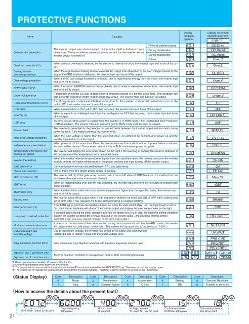
PROTECTIVE FUNCTIONSNameOver-current protectionOverload protection(*1)Braking resistoroverload protectionOver-voltage protectionEEPROM error(*2)Under-voltage errorCT(Current transformer) errorCPU errorExternal tripUSP errorGround faultInput over-voltage protectionInstantaneous power failureTemperature error due to lowcooling-fan speedInverter thermal tripGate array errorPhase loss detectionMain circuit error (*3)IGBT errorThermistor errorBraking errorEmergency stop (*4)Low-speed overload protectionModbus communication errorOut of operation dueto under-voltageEasy sequence function ErrorExpansion card 1 connection errorExpansion card 2 connection errorCause(s)The inverter output was short-circuited, or the motor shaft is locked or has aheavy load. These conditions cause excessive current for the inverter, so theinverter output is turned off.Communication error has occurred between CPU and gate array.One of three lines of 3-phase power supply is missing.An error has been detected in an expansion card or at its connecting terminals.While at constant speedDuring decelerationDuring accelerationOthersWhen a motor overload is detected by the electronic thermal function, the inverter trips and turns off its output.When the regenerative braking resistor exceeds the usage time allowance or an over-voltage caused by thestop of the BRD function is detected, the inverter trips and turns off its output.When the DC bus voltage exceeds a threshold, due to regenerative energy from the motor, the inverter tripsand turns off its output.When the built-in EEPROM memory has problems due to noise or excessive temperature, the inverter tripsand turns off its output.A decrease of internal DC bus voltage below a threshold results in a control circuit fault. This condition canalso generate excessive motor heat or cause low torque. The inverter trips and turns off its output.If a strong source of electrical interference is close to the inverter or abnormal operations occur in thebuilt-in CT, the inverter trips and turns off its output.When a malfunction in the built-in CPU has occurred, the inverter trips and turns off its output.When a signal to an intelligent input terminal configured as EXT has occurred, the inverter trips and turnsoff its output.An error occurs when power is cycled while the inverter is in RUN mode if the Unattended Start Protection(USP) is enabled. The inverter trips and does not go into RUN mode until the error is cleared.The inverter is protected by the detection of ground faults between the inverter output and the motor duringpower-up tests. This feature protects the inverter only.When the input voltage is higher than the specified value, it is detected 60 seconds after power-up and theinverter trips and turns of its output.When power is cut for more than 15ms, the inverter trips and turns off its output. If power failure continues,the error will be cleared. The inverter restarts if it is in RUN mode when power is cycled.The inverter will display the error code shown on the right if the lowering of cooling-fan speed is detected atthe occurrence of the temperature error described below.When the inverter internal temperature is higher than the specified value, the thermal sensor in the invertermodule detects the higher temperature of the power devices and trips, turning off the inverter output.The inverter will trip if the gate array cannot confirm the on/off state of IGBT because of a malfunction dueto noise or damage to the main circuit element.When an instantaneous over-current has occurred, the inverter trips and turns off its output to protect maincircuit element.When the thermistor inside the motor detects temperature higher than the specified value, the inverter tripsand turns off its output.The inverter turns off its output when it can not detect whether the braking is ON or OFF within waiting timeset at b024 after it has released the brake. (When braking is enabled at b120)If the EMR signal (on three terminals) is turned on when the slide switch (SW1) on the logic board is set toON, the inverter hardware will shut off the inverter output and display the error code shown on the right.If overload occurs during the motor operation at a very low speed at 0.2 Hz or less, the electronic thermal protectioncircuit in the inverter will detect the overload and shut off the inverter output. (2nd electronic thermal control)(Note that a high frequency may be recorded as the error history data.)If timeout occurs because of line disconnection during the communication in Modbus-RTU mode, the inverterwill display the error code shown on the right. (The inverter will trip according to the setting of "C076".)Due to insufficient voltage, the inverter has turned off its output and been trying torestart. If it fails to restart, it goes into the under-voltage error.Error indications by protective functions with the easy sequence function used.*1: Reset operation is acceptable 10 seconds after the trip.*2: Check the parameters when EEPROM error occurs.*3: The inverter will not accept reset commands input via the RS terminal or entered by the STOP/RESET key. Therefore, turn off the inverter power.*4: The inverter will not accept the reset command entered from the digital operator. Therefore, reset the inverter by turning on the RS terminal.Displayon digitaloperatorDisplay on remoteoperator/copy unitERR1****OC.DriveOC.DecelOC.AccelOver.COver.LOL.BRDOver.VEEPROMUnder.VCTCPUEXTERNALUSPGND.Flt.OV.SRCInst.P-FOH.stFANOH FINGAPH.FailMain.CirIGBTTHBRAKEEMROL-LowSPNET.ERRUV.WAITPRG.CMDPRG.NSTPRG.ERR1OP1-0 OP1-9OP2-0 OP2-9Status DisplayCode Description0Reset1StopCode23DescriptionDecelerationConstant SpeedCode45DescriptionAccelerationf0 StopCode67DescriptionStartingDBCode89DescriptionOverload RestrictionForcible or servo-onHow to access the details about the present fault21Error codeStatus at trip pointOutput frequencyat trip pointMotor currentat trip pointVoltage betweenP(+) and N() attrip pointCumulative inverterRUN time at trip pointCumulative power-ontime at trip point


