

SJ700 Series Brochure - Hitachi America, Ltd.
SJ700 Series Brochure - Hitachi America, Ltd.
SJ700 Series Brochure - Hitachi America, Ltd.

Create successful ePaper yourself
Turn your PDF publications into a flip-book with our unique Google optimized e-Paper software.
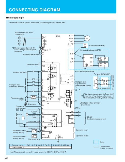
CONNECTING DIAGRAMSink type logicIn case of 400V class, place a transformer for operating circuit to receive 200V.200V-240V+10%, -15%50/60Hz±5%(*2)Remove connection with J51when RoTo power is suppliedexternallyControl power sourceRR(L1)S(L2)T(L3)T(J51)R0T0(*2)<strong>SJ700</strong>(T1)U(T2)V(T3)W(+1)PD(+) PIMDC link choke(Note 1)Dynamic braking unit (BRD)Short-circuit barP24PLCRB(-) NPNRBR1R2AL1AL2AL1AL2RBPRBPForward commandIntelligent inputterminals(8 terminals)FM monitor output(PWM)Frequencysetting device500-2k½DC0-10V- +ThermistorDC0-10V(12bit)DC-10-+10V(12bit)DC4-20mA(12bit)FW8761FMCM1THHOO2OIL100½10k½10k½DC10VDC24VAL0AL1AL2SPSNRPSNFor 30kW(40HP) and overIntelligent relayoutput contacts(default:alarm output)*11511CM2For up to 22kW(30HP)(Inverter)PNPRB RBBraking resistor(RB)(To operating circuit)The alarm relay contacts ALO and AL2when it is in Trip Mode or when inputPower is OFF,by factory default setting.*1( )Intelligent output terminals(5 terminals)RS-485Serial communication portAM monitor output(Analog output)AM monitor output(Analog output)DC0-10V(10bit)DC4-20mA(10bit)AMAMI(G)Expansion card 1Expansion card 2OptionTerminal NameCommon terminalFW, 1, 2, 3, 4, 5, 6, 7, 8, FM, THCM1H, O, O2, OI, AM, AMILCustomer wiring(Outside the inverter)Note1:Please be sure to connect DC reactor attached to 1850HF, 3150HF and 4000HF.23


