

SJ700 Series Brochure - Hitachi America, Ltd.
SJ700 Series Brochure - Hitachi America, Ltd.
SJ700 Series Brochure - Hitachi America, Ltd.

Create successful ePaper yourself
Turn your PDF publications into a flip-book with our unique Google optimized e-Paper software.
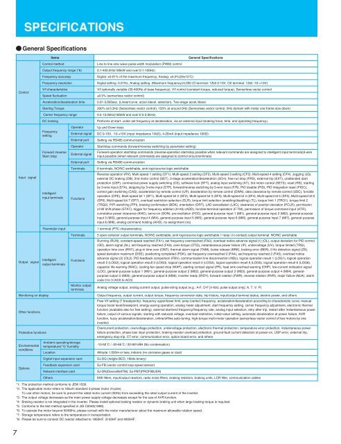
SPECIFICATIONSGeneralSpecificationsControlInputsignalOutputsignalMonitoring on displayOther functionsProtective functionsEnvironmentalconditionsOptionsItemsControl methodOutput frequency range (*6)Frequency accuracyFrequency resolutionV/f characteristicsSpeed fluctuationAcceleration/deceleration timeStarting TorqueCarrier frequency rangeDC brakingFrequencysettingOperatorExternal signalExternal portOperatorForward /reverseExternal signalStart /stopExternal portTerminalsIntelligent input terminalsThermistor inputIntelligent output terminalsFunctionsTerminalsFunctionsMonitor output terminalsAmbient operating/storage temperature(*7)/ humidityLocationDigital input expansion cardFeedback expansion cardNetwork interface cardOthersGeneralSpecificationsLine to line sine wave pulse-width modulation (PWM) control0.1-400.0Hz(185kW and over:0.1-120Hz)Digital: ±0.01% of the maximum frequency, Analog: ±0.2%(25±10ûC)Digital setting: 0.01Hz, Analog setting: (Maximum frequency)/4,000 (O terminal: 12bit 0-10V, O2 terminal: 12bit -10-+10V)V/f optionally variable (30-400Hz of base frequency), V/f control (constant torque, reduced torque), Sensorless vector control±0.5% (sensorless vector control)0.01-3,600sec. (Linear/curve, accel./decel. selection), Two-stage accel./decel.200% at 0.3Hz (Sensorless vector control), 150% at around 0Hz (Sensorless vector control, 0Hz domain with motor one frame size down)0.5-15.0kHz(185kW and over:0.5-3.0kHz)Performs at start: under set frequency at deceleration, via an external input (braking force, time, and operating frequency).Up and Down keysDC 0-10V, -10-+10V (input impedance 10k½), 4-20mA (input impedance 100½)Setting via RS485 communicationStart/stop commands (forward/reverse switching by parameter setting)Forward-operation start/stop commands (reverse-operation start/stop possible when relevant commands are assigned to intelligent input terminals)3-wireinput possible (when relevant commands are assigned to control circuit terminals)Setting via RS485 communication8 terminals, NO/NC switchable, sink logic/source logic switchableReverse operation (RV), Multi-speed 1 setting (CF1), Multi-speed 2 setting (CF2), Multi-speed 3 setting (CF3), Multi-speed 4 setting (CF4), Jogging (JG),external DC braking (DB), 2nd motor control (SET), 2-stage acceleration/deceleration (2CH), free-run stop (FRS), external trip (EXT), unattended startprotection (USP), commercial power supply switching (CS), software lock (SFT), analog input switching (AT), 3rd motor control (SET3), reset (RS), startingby 3-wire input (STA), stopping by 3-wire input (STP), forward/reverse switching by 3-wire input (F/R), PID disable (PID), PID integration reset (PIDC),control gain switching (CAS), acceleration by remote control (UP), deceleration by remote control (DWN), data clearance by remote control (UDC), forcibleoperation (OPE), Multi-speed bit 1 (SF1), Multi-speed bit 2 (SF2), Multi-speed bit 3 (SF3), Multi-speed bit 4 (SF4), Multi-speed bit 5 (SF5), Multi-speed bit 6(SF6), Multi-speed bit 7 (SF7), overload restriction selection (OLR), torque limit selection (enabling/disabling) (TL), torque limit 1 (TRQ1), torque limit 2(TRQ2), P/PI switching (PPI), braking confirmation (BOK), orientation (ORT), LAD cancellation (LAC), clearance of position deviation (PCLR), permissionof 90ûshift phase (STAT), trigger for frequency addition (A145) (ADD), forcible-terminal operation (F-TM), permission of torque command input (ATR),cumulative power clearance (KHC), servo-on (SON), pre-excitation (FOC), general-purpose input 1 (MI1), general-purpose input 2 (MI2), general-purposeinput 3 (MI3), general-purpose input 4 (MI4), general-purpose input 5 (MI5), general-purpose input 6 (MI6), general-purpose input 7 (MI7), general-purposeinput 8 (MI8), analog command holding (AHD), no assignment (no)1 terminal (PTC characteristics)5 open-collector output terminals, NO/NC switchable, sink logic/source logic switchable 1 relay (1c-contact) output terminal: NO/NC switchableRunning (RUN), constant-speed reached (FA1), set frequency overreached (FA2), overload notice advance signal (1) (OL), output deviation for PID control(OD), alarm signal (AL), set frequency reached (FA3), over-torque (OTQ), instantaneous power failure (IP), undervoltage (UV), torque limited (TRQ),operation time over (RNT), plug-in time over (ONT), thermal alarm signal (THM), brake release (BRK), braking error (BER), 0 Hz detection signal (ZS),speed deviation maximum (DSE), positioning completed (POK), set frequency overreached 2 (FA4), set frequency reached 2 (FA5), overload noticeadvance signal (2) (OL2), PID feedback comparison (FBV), communication line disconnection (NDc), logical operation result 1 (LOG1), logical operationresult 2 (LOG2), logical operation result 3 (LOG3), logical operation result 4 (LOG4), logical operation result 5 (LOG5), logical operation result 6 (LOG6),capacitor life warning (WAC), cooling-fan speed drop (WAF), starting contact signal (FR), heat sink overheat warning (OHF), low-current indication signal(LOC), general-purpose output 1 (M01), general-purpose output 2 (M02), general-purpose output 3 (M03), general-purpose output 4 (M04), generalpurposeoutput 5 (M05), general-purpose output 6 (M06), inverter ready (IRDY), forward rotation (FWR), reverse rotation (RVR), major failure (MJA), alarmcode 0 to 3 (AC0 to AC3)Analog voltage output, analog current output, pulse-string output (e.g., A-F, D-F [n-fold, pulse output only], A, T, V, P)Output frequency, output current, output torque, frequency conversion data, trip history, input/output terminal status, electric power, and othersFree V/f setting (7 breakpoints), frequency upper/lower limit, jump (center) frequency, acceleration/deceleration according to characteristic curve, manualtorque boost level/breakpoint, energy-saving operation, analog meter adjustment, start frequency setting, carrier frequency adjustment, electronic thermalfunction (available also for free setting), external start/end frequency/frequency rate, analog input selection, retry after trip, restart after instantaneous powerfailure, output of various signals, starting with reduced voltage, overload restriction, initial-value setting, automatic deceleration at power failure, AVRfunction, fuzzy acceleration/deceleration, online/offline auto-tuning, high-torque multi-motor operation (sensorless vector control of two motors by oneinverter)Overcurrent protection, overvoltage protection, undervoltage protection, electronic thermal protection, temperature error protection, instantaneous powerfailure protection, phase loss input protection, braking-resistor overload protection, ground-fault current detection at power-on, USP error, external trip,emergency stop trip, CT error, communication error, option board error, and others-10-50ûC / -20-65ûC / 20-90%RH (No condensation)Altitude 1,000m or less, indoors (no corrosive gases or dust)SJ-DG (4digits BCD, 16bits binary)SJ-FB (vector control loop speed sensor)SJ-DN(DeviceNetTM), SJ-PBT(PROFIBUSR)EMI filters, input/output reactors, radio noize filters, braking resistors, braking units, LCR filter, communication cables*1: The protection method conforms to JEM 1030.*2: The applicable motor refers to <strong>Hitachi</strong> standard 3-phase motor (4-pole).To use other motors, be sure to prevent the rated motor current (50Hz) from exceeding the rated output current of the inverter.*3: The output voltage decreases as the main power supply voltage decreases except for the use of AVR function.*4: Braking resistor is not integrated in the inverter. Please install optional braking resistor or dynamic braking unit when large braking torque is required.*5: Conforms to the test method specified in JIS C0040(1999).*6: To operate the motor beyond 50/60Hz, please consult with the motor manufacturer about the maximum allowable rotation speed.*7: Storage temperature refers to the temperature in transportation.*8: Please be sure to connect DC reactor attached to 1850HF, 3150HF and 4000HF.7


