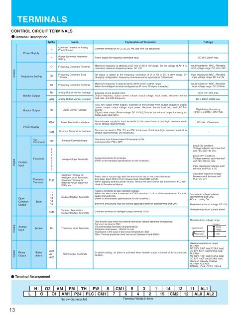
TERMINALSCONTROL CIRCUIT TERMINALSTerminal DescriptionSymbol Name Explanation of Terminals RatingsPower SupplyLHCommon Terminal for AnalogPower SourcePower Source for FrequencySettingCommon terminal for H, O, O2, OI, AM, and AMI. Do not ground. -Power supply for frequency command inputDC 10V, 20mA max.OFrequency Command TerminalMaximum frequency is attained at DC 10V in DC 0-10V range. Set the voltage at A014 tocommand maximum frequency below DC 10V.Input impedance: 10k½, Allowableinput voltage range: DC -0.3-+12VAnalogFrequency SettingO2Frequency Command ExtraTerminalO2 signal is added to the frequency command of O or OI in DC 0-±10V range. Bychanging configuration, frequency command can be input also at O2 terminal.Input impedance:10k½, Allowableinput voltage range: DC 0-±12VOIFrequency Command TerminalMaximum frequency is attained at DC 20mA in DC 4-20mA range.When the intelligent terminal configured as AT is on, OI signal is enabled.Input impedance: 100½, Allowableinput voltage range: DC 0-24mAMonitor OutputAMAMIAnalog Output Monitor (Voltage)Analog Output Monitor (Current)Selection of one function from:Output frequency, output current, torque, output voltage, input power, electronic thermalload ratio, and LAD frequency.DC 0-10V, 2mA max.DC 4-20mA, 250½ max.Monitor OutputFMDigital Monitor (Voltage)[DC0-10V output (PWM output)] Selection of one function from: Output frequency, outputcurrent, torque, output voltage, input power, electronic thermal load ratio, and LAD frequency.[Digital pulse output (Pulse voltage DC 0/10V)] Outputs the value of output frequency asdigital pulse (duty 50%)Digital output frequencyrange: 0-3.6kHz, 1.2mA max.Power SupplyP24CM1Power Terminal for InterfaceCommon Terminal for InterfaceInternal power supply for input terminals. In the case of source type logic, common terminalfor contact input terminals.Common terminal for P24, TH, and FM. In the case of sink type logic, common terminal forcontact input terminals. Do not ground.DC 24V, 100mA max.-DigitalContactInputRunCommandFunctionsFW12345678Forward Command InputIntelligent Input TerminalsThe motor runs forward when FW terminal is ON,and stops when FW is OFF.Assign 8 functions to terminals.(Refer to the standard specifications for the functions.)[Input ON condition]Voltage between each terminaland PLC: DC 18V min.[Input OFF condition]Voltage between each terminaland PLC: DC 3V max.Input impedance between eachterminal and PLC: 4.7½CommonTerminalPLCCommon Terminal forIntelligent Input Terminals,Common Terminal forExternal Power Supply forPLCs, etc.Select sink or source logic with the short-circuit bar on the control terminals.Sink logic: Short P24 to PLC /Source logic: Short CM1 to PLC.When applying external power source, remove the short-circuit bar and connect PLC terminalto the external device.Allowable maximum voltagebetween each terminal andPLC: DC 27VOpenCollectorOutputState1112131415Intelligent Output TerminalsAssign 5 functions to open collector outputs.When the alarm code is selected at C062, terminal 11-13 or 11-14 are reserved for errorcodes of inverter trip.(Refer to the standard specifications for the functions.)Both sink and source logic are always applicable between each terminal and CM1.Decrease in voltage betweeneach terminal and CM2:4V max. during ONAllowable maximum voltage: DC 27VCM2Common Terminal forIntelligent Output TerminalsCommon terminal for intelligent output terminal 11-15.Allowable maximum current: 50mAAnalogAnalogInputSensorTHThermistor Input TerminalsThe inverter trips when the external thermistor detects abnormal temperature.Common terminal is CM1.[Recommended thermistor characteristics]Allowable rated power: 100mW or over.Impedance in the case of abnormal temperature: 3k½Note: Thermal protection level can be set between 0 and 9999½.Allowable input voltage range[Input Circuit]THThermistorCM1DC0-8VDC8V10k½1k½DigitalRelayOutputState/AlarmAL0AL1AL2Alarm Output TerminalsIn default setting, an alarm is activated when inverter output is turned off by a protectivefunction.Maximum capacity of relaysAL1-AL0:AC 250V, 2A(R load)/0.2A(L load)DC 30V, 8A(R load)/0.6A(L load)AL2-AL0:AC 250V, 1A(R load)/0.2A(L load)DC 30V, 1A(R load)/0.2A(L load)Minimum capacity of relaysAL1-AL0, AL2-AL0:AC100V, 10mA DC5V, 100mATerminal ArrangementLHOO2 AM FM TH FW 8OI AM1 P24 PLC CM1Screw diameter:M3CM1 5 37 6 4 2Terminal Width:6.4mm114 13 11 AL115 CM2 12 AL0 AL213
PROTECTIVE FUNCTION LIST FUNCTIONSMONITORINGFUNCTIONS and MAIN PROFILE PARAMETERSMonitor ModeSetting ModeExpanded FunctionA GROUP: STANDARD FUNCTIONSBasic settingsAnalog input and othersCoded001d002d003d004d005d006d007d008d009d010d012d013d014d015d016d017d018d019d022d023d024d025d026d027d028d029d030d080d081d086d090d102d103d104F001F002F202F302F003F203F303F004A---b---C---H---P---U----CodeA001A002A003A203A303A004A204A304A005A006A011A012Output frequency monitorOutput current monitorRotation direction minitoringProcess variable (PV), PID feedback monitorIntelligent input terminal statusIntelligent output terminal statusScaled output frequency monitoringActual-frequency monitoringTorque command monitoringTorque bias monitoringTorque monitoringOutput voltage monitoringPower monitoringCumulative power monitoringCumulative operation RUN time monitoringCumulative power-on time monitoringHeat sink temperature monitoringMotor temperature monitoringLife-check monitoringProgram counterProgram number monitoringUser monitor 0User monitor 1User monitor 2Pulse counterPosition setting monitorPosition feedback monitorTrip CounterTrip monitoring 1-6Programming error monitoringDC voltage monitoringBRD load factor monitoringElectronic thermal overload monitoringOutput frequency settingFunction NameAcceleration (1) time settingAcceleration (1) time setting, 2nd motorAcceleration (1) time setting, 3rd motorDeceleration (1) time settingDeceleration time setting, 2nd motorDeceleration time setting, 3rd motorKeypad Run key routingA Group: Standard functionsb Group: Fine tuning functionsC Group: Intelligent terminal functionsH Group: Motor constants functionsP Group: Expansion card functionsU Group: User-selectable menu functionsFrequency source settingRun command source settingBase frequency settingBase frequency setting, 2nd motorBase frequency setting, 3rd motorMaximum frequency settingMaximum frequency setting, 2nd motorMaximum frequency setting, 3rd motor[AT] selection[O2] selectionFunction NameO-L input active range start frequencyO-L input active range end frequency*1 This setting is valid only when the OPE-SR is connected.Monitored data or setting0.00 to 99.99, 100.0 to 400.0 (Hz)0.0 to 999.9, 1000 to 9999 (A)F (forward rotation), o (stopped), r (reverse rotation)0.00 to 99.99, 100.0 to 999.9, 1000. to 9999. 1000 to 9999 (10000 to 99990), 100 to 999 (10000 to 999000)FW8 7 6 54 3 2 1AL 15 14 13 12 11(Example) FW, 7, 2, 1:ON8, 6, 5, 4, 3 : OFF(Example) 12, 11 : ONAL, 15, 14, 13 :OFF0.00 to 99.99, 100.0 to 999.9, 1000. to 9999., 1000 to 3996 (10000 to 39960)-400. to -100., -99.9 to 0.00 to 99.99, 100.0 to 400.0 (Hz)-200. to +200. (%)-200. to +200. (%)-200. to +200. (%)0.0 to 600.0 (V)0.0 to 999.9 (kW)0.0 to 999.9, 1000. to 9999.1000 to 9999 (10000 to 99990), 100 to 999 (100000 to 999000)0. to 9999., 1000 to 9999 (10000 to 99990), 100 to 999 (10000 to 999000) (hr)0. to 9999., 1000 to 9999 (10000 to 99990), 100 to 999 (10000 to 999000) (hr)-020. to 200.0 ()-020. to 200.0 ()2 10to5120000 to 9999-2147483647 to 2147483647 (upper 4 digits including Ò-Ò)-2147483647 to 2147483647 (upper 4 digits including Ò-Ò)-2147483647 to 2147483647 (upper 4 digits including Ò-Ò)0to2147483647 (upper 4 digits)-1073741823 to 1073741823 (upper 4 digits including Ò-Ò)-1073741823 to 1073741823 (upper 4 digits including Ò-Ò)0. to 9999., 1000 to 6553 (10000 to 65530) (times)Factor, frequency (Hz), current (A), voltage across P-N (V),running time (hours), power-on time (hours)Warning code0.0 to 999.9 (V)0.0 to 100.0 (%)0.0 to 100.0 (%)0.0, "start frequency" to "maximum frequency" (or maximum frequency, 2nd/3rd motors) (Hz)0.0 to 100.0 (when PID function is enabled)0.01 to 99.99, 100.0 to 999.9, 1000. to 3600. (s)0.01 to 99.99, 100.0 to 999.9, 1000. to 3600. (s)0.01 to 99.99, 100.0 to 999.9, 1000. to 3600. (s)0.01 to 99.99, 100.0 to 999.9, 1000. to 3600. (s)0.01 to 99.99, 100.0 to 999.9, 1000. to 3600. (s)0.01 to 99.99, 100.0 to 999.9, 1000. to 3600. (s)00 (forward rotation), 01 (reverse rotation)01 (control circuit terminal block), 02 (digital operator), 03 (RS485), 04 (option 1), 05 (option 2)30. to "maximum frequency " (Hz)30. to "maximum frequency, 2nd motor" (Hz)30. to "maximum frequency, 3rd motor" (Hz)30. to 400. (Hz)30. to 400. (Hz)30. to 400. (Hz)0.00 to 99.99, 100.0 to 400.0 (Hz)0.00 to 99.99, 100.0 to 400.0 (Hz)ONOFFONOFFONOFFMonitored data or setting1: Capacitor on main circuit board2: Cooling-fan speed drop00 (keypad potentiometer) (*1), 01 (control circuit terminal block),02 (digital operator), 03 (RS485), 04 (option 1), 05 (option 2),06 (pulse-string input), 07 (easy sequence), 10 (operation function result)00 (switching between O and OI terminals), 01 (switching between O and O2 terminals),02 (switching between O terminal and keypad potentiometer) (*1), 03 (switching between OI terminaland keypad potentiometer) (*1), 04 (switching between O2 and keypad potentiometer) (*1)00 (single), 01 (auxiliary frequency input via O and OI terminals) (nonreversible),02 (auxiliary frequency input via O and OI terminals) (reversible), 03 (disabling O2 terminal)Default Setting-FE(CE) -FU(UL)--------------------------------= Allowed = Not permitted-F(JP)----0.00Hz 0.00Hz 0.00Hz30.00s30.00s30.00s30.00s30.00s30.00s00010150.50.50.50.50.50.00030.000.00---------------------------------30.00s30.00s30.00s30.00s30.00s30.00s00010160.60.60.60.60.60.00030.000.00-----------------------------30.00s30.00s30.00s30.00s30.00s30.00s00020260.60.60.60.60.60.00030.000.00Settingduring operation(allowed or not) Changeduring operation(allowed or not) = Allowed = Not permittedDefault Setting Setting Changeduring operation during operation-FE(CE) -FU(UL) -F(JP) (allowed or not) (allowed or not)14