Window comparatorOthersFree setting of V/f characteristicOthersCodeb056b060b061b062b063b064b065b066b067b068b070b071b072b078b079b082b083b084b085b086b087b088b089b090b091b092b095b096b098b099b100b101b102b103b104b105b106b107b108b109b110b111b112b113b120b121b122b123b124b125b126b127b130b131b132b133b134Function NameIntegral time setting for nonstop operation at power lossMaximum-limit level of window comparators OMinimum-limit level of window comparators OHysteresis width of window comparators OMaximum-limit level of window comparators OIMinimum-limit level of window comparators OIHysteresis width of window comparators OIMaximum-limit level of window comparators OIMinimum-limit level of window comparators O/OI/O2Hysteresis width of window comparators O/OI/O2Operation level at O disconnectionOperation level at OI disconnectionOperation level at O2 disconnectionCumulative input power data clearanceCumulative input power display gain settingStart frequency adjustmentCarrier frequency settingInitialization mode (parameters or trip history)Country code for initializationFrequency scaling conversion factorSTOP key enableRestart mode after FRSAutomatic carrier frequency reductionDynamic braking usage ratioStop mode selectionCooling fan controlDynamic braking controlDynamic braking activation levelThermistor for thermal protection controlThermal protection level settingFree-setting V/f frequency (1)Free-setting V/f voltage (1)Free-setting V/f frequency (2)Free-setting V/f voltage (2)Free-setting V/f frequency (3)Free-setting V/f voltage (3)Free-setting V/f frequency (4)Free-setting V/f voltage (4)Free-setting V/f frequency (5)Free-setting V/f voltage (5)Free-setting V/f frequency (6)Free-setting V/f voltage (6)Free-setting V/f frequency (7)Free-setting V/f voltage (7)Brake control enableBrake wait time for releaseBrake wait time for accelerationBrake wait time for stoppingBrake wait time for confirmationBrake release frequency settingBrake release current settingBraking frequencyOvervoltage suppression enableOvervoltage suppression levelAcceleration and deceleration rate at overvoltage suppressionOvervoltage suppression propotional gainOvervoltage suppression Integral time= Allowed = Not permittedMonitored data or settingDefault Setting Settingduring operation-FE(CE) -FU(UL) -F(JP) (allowed or not)0.0 to 9.999 /10.00 to 65.550. to 100. (lower limit : b061 + b062*2) (%)0. to 100. (lower limit : b060 - b062*2) (%)0. to 10. (lower limit : b061 - b062 / 2) (%)0. to 100. (lower limit : b064 + b066*2) (%)0. to 100. (lower limit : b063 - b066*2) (%)0. to 10. (lower limit : b063 - b064 / 2) (%)-100. to 100. (lower limit : b067 + b068*2) (%)-100. to 100. (lower limit : b066 - b068*2) (%)0. to 10. (lower limit : b066 - b067 / 2) (%)0.1001000010000100-10000.1001000010000100-10000.1001000010000100-10000to100 (%) or "no" (ignore)0to100 (%) or "no" (ignore)0to100 (%) or "no" (ignore)255(no) 255(no) 255(no)255(no) 255(no) 255(no)127(no) 127(no) 127(no)Clearance by setting "01" and pressing the STR key1. to 1000.0.10 to 9.99 (Hz)0.5 to 15.0 (kHz) (subject to derating)00 (clearing the trip history), 01 (initializing the data), 02 (clearing the trip history and initializing the data)00 (Japan), 01 (EU), 02 (U.S.A.)0.1 to 99.000 (enabling), 01 (disabling), 02 (disabling only the function to stop)00 (starting with 0 Hz), 01 (starting with matching frequency), 02 (starting with active matching frequency)00: invalid, 01: valid0.0 to 100.0 (%)00 (deceleration until stop), 01 (free-run stop)00 (always operating the fan), 01 (operating the fan only during inverter operation[including 5 minutes after power-on and power-off])00 (disabling), 01 (enabling [disabling while the motor is topped]), 02 (enabling [enabling also while the motor is topped])001.0.505.000011.00000000.0000000001.0.505.000011.00000000.0000000001.0.505.000011.00000000.0000000330 to 380, 660 to 760(V)360/720 360/720 360/720 00 (disabling the thermistor), 01 (enabling the thermistor with PTC), 02 (enabling the thermistor with NTC)0. to 9999. ()0. to "free-setting V/f frequency (2)" (Hz)0.0 to 800.0 (V)0. to "free-setting V/f frequency (3)" (Hz)0.0 to 800.0 (V)0. to "free-setting V/f frequency (4)" (Hz)0.0 to 800.0 (V)0. to "free-setting V/f frequency (5)" (Hz)0.0 to 800.0 (V)0. to "free-setting V/f frequency (6)" (Hz)0.0 to 800.0 (V)0. to "free-setting V/f frequency (7)" (Hz)0.0 to 800.0 (V)0.0 to 400.0 (Hz)0.0 to 800.0 (V)00 (disabling), 01 (enabling)0.00 to 5.00 (s)0.00 to 5.00 (s)0.00 to 5.00 (s)0.00 to 5.00 (s)0.00 to 99.99, 100.0 to 400.0 (Hz)003000.0.0.00.0.00.0.00.0.00.0.00.0.00.0.0000.000.000.000.000.00003000.0.0.00.0.00.0.00.0.00.0.00.0.00.0.0000.000.000.000.000.00003000.0.0.00.0.00.0.00.0.00.0.00.0.00.0.0000.000.000.000.000.000.0 to 2.00 x "rated current"Rated current of inverterx 1..0 0.00 to 99.99, 100.0 to 400.0 (Hz)00 (disabling the restraint), 01 (decelerating and stagnating), 02 (enabling acceleration)0.00000.00000.0000330 to 390 (V) (200 V class model), 660 to 780 (V) (400 V class model)380/760 380/760 380/760 0.10 to 30.00 (s)0.00 to 2.550.000 to 9.999 / 10.00 to 63.53 (s)1.000.500.0601.000.500.0601.000.500.060Changeduring operation(allowed or not)C GROUP: INTELLIGENT TERMINAL FUNCTIONSIntelligent input terminals17CodeC001C002C003C004C005C006C007C008Terminal [1] function (*2)Terminal [2] functionTerminal [3] function (*2)Terminal [4] functionTerminal [5] functionTerminal [6] functionTerminal [7] functionTerminal [8] functionFunction NameMonitored data or setting01 (RV: Reverse RUN), 02 (CF1: Multispeed 1 setting), 03 (CF2: Multispeed 2 setting),04 (CF3: Multispeed 3 setting), 05 (CF4: Multispeed 4 setting), 06 (JG: Jogging), 07 (DB:external DC braking), 08 (SET: Set 2nd motor data), 09 (2CH: 2-stageacceleration/deceleration), 11 (FRS: free-run stop), 12 (EXT: external trip), 13 (USP:unattended start protection), 14: (CS: commercial power source enable), 15 (SFT: softwarelock), 16 (AT: analog input voltage/current select), 17 (SET3: 3rd motor control), 18 (RS: reset),20 (STA: starting by 3-wire input), 21 (STP: stopping by 3-wire input), 22 (F/R: forward/reverseswitching by 3-wire input), 23 (PID: PID disable), 24 (PIDC: PID reset), 26 (CAS: control gainsetting), 27 (UP: remote control UP function), 28 (DWN: remote control DOWN function), 29(DWN: remote control data clearing), 31 (OPE: forcible operation), 32 (SF1: multispeed bit 1),33 (SF2: multispeed bit 2), 34 (SF3: multispeed bit 3), 35 (SF4: multispeed bit 4), 36 (SF5:multispeed bit 5), 37 (SF6: multispeed bit 6), 38 (SF7: multispeed bit 7), 39 (OLR: overloadrestriction selection), 40 (TL: torque limit enable), 41 (TRQ1: torque limit selection bit 1), 42(TRQ2: torque limit selection bit 2), 43 (PPI: P/PI mode selection), 44 (BOK: brakingconfirmation), 45 (ORT: orientation), 46 (LAC: LAD cancellation), 47 (PCLR: clearance ofposition deviation), 48 (STAT: pulse train position command input enable), 50 (ADD: trigger forfrequency addition [A145]), 51 (F-TM: forcible-terminal operation), 52 (ATR: permission oftorque command input), 53 (KHC: cumulative power clearance), 54 (SON: servo-on), 55 (FOC:pre-excitation), 56 (MI1: general-purpose input 1), 57 (MI2: general-purpose input 2), 58 (MI3:general-purpose input 3), 59 (MI4: general-purpose input 4), 60 (MI5: general-purpose input 5),61 (MI6: general-purpose input 6), 62 (MI7: general-purpose input 7), 63 (MI8: general-purposeinput 8), 65 (AHD: analog command holding), 66 (CP1: multistage position settings selection 1), 67 (CP2: multistage position settings selection 2), 68 (CP3: multistage position settingsselection 3), 69 (ORL: Zero-return limit function), 70 (ORG: Zero-return trigger function), 71(FOT: forward drive stop), 72 (ROT: reverse drive stop), 73 (SPD: speed / position switching),74 (PCNT: pulse counter), 75 (PCC: pulse counter clear), no (NO: no assignment)= Allowed = Not permittedDefault Setting Setting Changeduring operation during operation-FE(CE) -FU(UL) -F(JP) (allowed or not) (allowed or not)18(RS) 18(RS) 18(RS)*2 When the emergency stop function is enabled (SW1 = ON), "18" (RS) and "64" (EMR) are forcibly written to parameters "C001" and "C003",respectively. (You cannot arbitrarily write "64" to "C001".) If the SW1 signal is turned off and then turned on, "no" (no assignment) is set in parameter "C003".16(AT)06(JG)16(AT)06(JG)16(AT)06(JG)11(FRS) 11(FRS) 11(FRS)09(2CH) 09(2CH) 09(2CH)03(CF2) 13(USP) 03(CF2)02(CF1) 02(CF1) 02(CF1)01(RV) 01(RV) 01(RV)
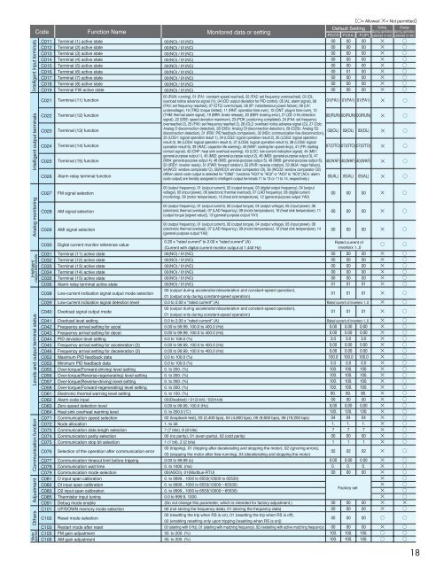
Intelligentoutput terminals Analog monitoringIntelligent output terminals Intelligent input terminalsLevels and output terminal statusCommunication functionAdjustmentOthersMeteradjustmentCodeC011C012C013C014C015C016C017C018C019C021C022C023C024C025C026C027C028C029Terminal (1) active stateTerminal (2) active stateTerminal (3) active stateTerminal (4) active stateTerminal (5) active stateTerminal (6) active stateTerminal (7) active stateTerminal (8) active stateTerminal FW active stateTerminal (11) functionTerminal (12) functionTerminal (13) functionTerminal (14) functionTerminal (15) functionAlarm relay terminal functionFM signal selectionAM signal selectionAMI signal selectionFunction NameC030 Digital current monitor reference valueC031 Terminal (11) active stateC032 Terminal (12) active stateC033 Terminal (13) active stateC034 Terminal (14) active stateC035 Terminal (15) active stateC036 Alarm relay terminal active stateC038 Low-current indication signal output mode selectionC039 Low-current indication signal detection levelC040 Overload signal output modeC041 Overload level settingC042 Frequency arrival setting for accel.C043 Frequency arrival setting for decel.C044 PID deviation level settingC045 Frequency arrival setting for acceleration (2)C046 Frequency arrival setting for deceleration (2)C052 Maximum PID feedback dataC053 Minimum PID feedback dataC055 Over-torque(Forward-driving) level settingC056 Over-torque(Reverse-regenerating) level settingC057 Over-torque(Reverse-driving) level settingC058 Over-torque(Forward-regenerating) level settingC061 Electronic thermal warning level settingC062 Alarm code inputC063 Zero speed detection levelC064 Heat sink overheat warning levelC071 Communication speed selectionC072 Node allocationC073 Communication data length selectionC074 Communication parity selectionC075 Communication stop bit selectionC076 Selection of the operation after communication errorC077 Communication timeout limit before trippingC078 Communication wait timeC079 Communication mode selectionC081 O input span calibrationC082 OI input span calibrationC083 O2 input span calibrationC085 Thermistor input tuningC091 Debug mode enableC101 UP/DOWN memory mode selectionC102 Reset mode selectionC103 Restart mode after resetC105 FM gain adjustmentC106 AM gain adjustmentMonitored data or setting00(NO) / 01(NC)00(NO) / 01(NC)00(NO) / 01(NC)00(NO) / 01(NC)00(NO) / 01(NC)00(NO) / 01(NC)00(NO) / 01(NC)00(NO) / 01(NC)00(NO) / 01(NC)00 (RUN: running), 01 (FA1: constant-speed reached), 02 (FA2: set frequency overreached), 03 (OL:overload notice advance signal (1)), 04 (OD: output deviation for PID control), 05 (AL: alarm signal), 06(FA3: set frequency reached), 07 (OTQ: over-torque), 08 (IP: instantaneous power failure), 09 (UV:undervoltage), 10 (TRQ: torque limited), 11 (RNT: operation time over), 12 (ONT: plug-in time over), 13(THM: thermal alarm signal), 19 (BRK: brake release), 20 (BER: braking error), 21 (ZS: 0 Hz detectionsignal), 22 (DSE: speed deviation maximum), 23 (POK: positioning completed), 24 (FA4: set frequencyoverreached 2), 25 (FA5: set frequency reached 2), 26 (OL2: overload notice advance signal (2)), 27 (Odc:Analog O disconnection detection), 28 (OIDc: Analog OI disconnection detection), 29 (O2Dc: Analog O2disconnection detection), 31 (FBV: PID feedback comparison), 32 (NDc: communication line disconnection),33 (LOG1: logical operation result 1), 34 (LOG2: logical operation result 2), 35 (LOG3: logical operationresult 3), 36 (LOG4: logical operation result 4), 37 (LOG5: logical operation result 5), 38 (LOG6: logicaloperation result 6), 39 (WAC: capacitor life warning), 40 (WAF: cooling-fan speed drop), 41 (FR: startingcontact signal), 42 (OHF: heat sink overheat warning), 43 (LOC: low-current indication signal), 44 (M01:general-purpose output 1), 45 (M02: general-purpose output 2), 46 (M03: general-purpose output 3), 47(M04: general-purpose output 4), 48 (M05: general-purpose output 5), 49 (M06: general-purpose output 6),50 (IRDY: inverter ready), 51 (FWR: forward rotation), 52 (RVR: reverse rotation), 53 (MJA: major failure),54(WCO: window comparator O), 55(WCOI: window comparator OI), 56 (WCO2: window comparator O2)(When alarm code output is selected for "C062", functions "AC0" to "AC2" or "AC0" to "AC3" [ACn: alarmcode output] are forcibly assigned to intelligent output terminals 11 to 13 or 11 to 14, respectively.)00 (output frequency), 01 (output current), 02 (output torque), 03 (digital output frequency), 04 (outputvoltage), 05 (input power), 06 (electronic thermal overload), 07 (LAD frequency), 08 (digital currentmonitoring), 09 (motor temperature), 10 (heat sink temperature), 12 (general-purpose output YA0)00 (output frequency), 01 (output current), 02 (output torque), 04 (output voltage), 05 (input power), 06(electronic thermal overload), 07 (LAD frequency), 09 (motor temperature), 10 (heat sink temperature), 11(output torque [signed value]), 13 (general-purpose output YA1)00 (output frequency), 01 (output current), 02 (output torque), 04 (output voltage), 05 (input power), 06(electronic thermal overload), 07 (LAD frequency), 09 (motor temperature), 10 (heat sink temperature), 14(general-purpose output YA2)= Allowed = Not permittedDefault Setting Setting Changeduring operation during operation-FE(CE) -FU(UL) -F(JP) (allowed or not) (allowed or not)01(FA1) 01(FA1) 01(FA1)00(RUN) 00(RUN) 00(RUN)03(OL)07(OTO) 07(OTO) 07(OTO)40(WAF) 40(WAF) 40(WAF)05(AL)03(OL)05(AL)03(OL)05(AL)0.20 x "rated current" to 2.00 x "rated current" (A)(Current with digital current monitor output at 1,440 Hz)Rated current ofinverterx 1..000(NO) / 01(NC)00(NO) / 01(NC)00(NO) / 01(NC)00(NO) / 01(NC)00(NO) / 01(NC)00(NO) / 01(NC)00 (output during acceleration/deceleration and constant-speed operation),01 (output only during constant-speed operation)0000000000010100000000000101000000000001010.0 to 2.00 x "rated current" (A)Rated current of inverterx 1..000 (output during acceleration/deceleration and constant-speed operation),01 (output only during constant-speed operation)01 01 010.0 to 2.00 x "rated current" (A)Rated current of inverterx 1..00.00 to 99.99, 100.0 to 400.0 (Hz)0.00 to 99.99, 100.0 to 400.0 (Hz)0.0 to 100.0 (%)0.00 to 99.99, 100.0 to 400.0 (Hz)0.00 to 99.99, 100.0 to 400.0 (Hz)0.0 to 100.0 (%)0.0 to 100.0 (%)0. to 200. (%)0. to 200. (%)0. to 200. (%)0. to 200. (%)0. to 100. (%)00(Disabled) / 01(3-bit) / 02(4-bit)0.00 to 99.99, 100.0 (Hz)0. to 200.0 ()02 (loopback test), 03 (2,400 bps), 04 (4,800 bps), 05 (9,600 bps), 06 (19,200 bps)1. to 32.7(7bits), 8 (8 bits)00 (no parity), 01 (even parity), 02 (odd parity)1(1bit), 2 (2 bits)00 (tripping), 01 (tripping after decelerating and stopping the motor), 02 (ignoring errors),03 (stopping the motor after free-running), 04 (decelerating and stopping the motor)0.00 to 99.99 (s)0. to 1000. (ms)00(ASCII), 01(Modbus-RTU)0. to 9999., 1000 to 6553(10000 to 65530)0. to 9999., 1000 to 6553(1000065530)0.000.003.00.000.00100.00.0100.100.100.100.80.000,00120.041.7001020.000.000.000.003.00.000.00100.00.0100.100.100.100.80.000,00120.041.7001020.000.000.000.003.00.000.00100.00.0100.100.100.100.80.000,00120.041.7001020.000.000. to 9999., 1000 to 6553(1000065530)Factory set0.0 to 999.9, 1000.(Do not change this parameter, which is intended for factory adjustment.)00 (not storing the frequency data), 01 (storing the frequency data)00000000000000 (resetting the trip when RS is on), 01 (resetting the trip when RS is off), 00 00 0002 (enabling resetting only upon tripping [resetting when RS is on])00 (starting with 0 Hz), 01 (starting with matching frequency), 02 (restarting with active matching frequency)50. to 200. (%)50. to 200. (%)00100.100.00100.100.00100.100.00000000000000000000000000000000000100000000000000000000000000000000000018