Brenner für Gas Burner for gas BIO, BIOA, ZIO, BIC, BICA, BICF, BOCF
Brenner für Gas Burner for gas BIO, BIOA, ZIO, BIC, BICA, BICF, BOCF
Brenner für Gas Burner for gas BIO, BIOA, ZIO, BIC, BICA, BICF, BOCF

Create successful ePaper yourself
Turn your PDF publications into a flip-book with our unique Google optimized e-Paper software.
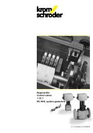
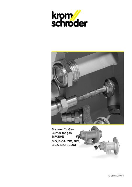
<strong>Brenner</strong> für <strong>Gas</strong><br />
<strong>Burner</strong> <strong>for</strong> <strong>gas</strong><br />
<strong>BIO</strong>, <strong>BIO</strong>A, <strong>ZIO</strong>, <strong>BIC</strong>,<br />
<strong>BIC</strong>A, <strong>BIC</strong>F, <strong>BOCF</strong><br />
7.2 Edition 2.03 CN
<strong>BIO</strong><br />
<strong>BIO</strong>A<br />
<strong>BIC</strong><br />
<strong>Brenner</strong> für <strong>Gas</strong><br />
<strong>BIO</strong>, <strong>BIO</strong>A, <strong>ZIO</strong>,<br />
<strong>BIC</strong>, <strong>BIC</strong>A, <strong>BIC</strong>F, <strong>BOCF</strong><br />
Leistungsbereich 1,5 bis 1000 kW<br />
Modularer Aufbau<br />
Hohe Austrittsgeschwindigkeit und<br />
hoher Impuls<br />
Direkt gezündet und überwacht<br />
Schadstoffarm durch optimierte<br />
Verbrennung<br />
Geringste NO x -Emissionen mit <strong>BIC</strong>F,<br />
<strong>BOCF</strong> durch flammenlose Oxidation<br />
(FLOX ® )<br />
FLOX ® ist ein eingetragenes<br />
Warenzeichen der WS-<br />
Wärmeprozeßtechnik GmbH.<br />
Kundenspezifische Varianten für<br />
unterschiedliche Einsatzzwecke und<br />
<strong>Gas</strong>arten, auch für indirekte<br />
Beheizungssysteme und Anlagen mit<br />
rekuperativer Wärmerückgewinnung<br />
Geeignet als Deckenoder Seitenbrenner<br />
<strong>Burner</strong>s <strong>for</strong> <strong>gas</strong><br />
<strong>BIO</strong>, <strong>BIO</strong>A, <strong>ZIO</strong>,<br />
<strong>BIC</strong>, <strong>BIC</strong>A, <strong>BIC</strong>F, <strong>BOCF</strong><br />
Capacity range 1.5 to 1000 kW<br />
Modular design<br />
High outlet velocity and high impulse<br />
Directly ignited and controlled<br />
Low pollutant emission thanks to<br />
optimised combustion<br />
Extremely low NO x emissions with<br />
<strong>BIC</strong>F, <strong>BOCF</strong> thanks to flameless<br />
oxidation (FLOX ® )<br />
FLOX ® is a registered trademark of<br />
WS-Wärmeprozeßtechnik GmbH.<br />
Customised versions <strong>for</strong> various<br />
applications and types of <strong>gas</strong>; also <strong>for</strong><br />
indirect heating systems and<br />
installations with recuperative heat<br />
recovery<br />
Suitable <strong>for</strong> use as roof or side burners<br />
Anwendung<br />
An Industrieöfen und Feuerungsanlagen<br />
–der Stahl- und Eisenindustrie,<br />
–im Edel-, Bunt-,und Leichtmetallbereich,<br />
–der Glas-, Grob- und Feinkeramik-,<br />
Steingut- oder Emailleindustrie,<br />
–in den Bereichen Erze, Steine, Erde oder<br />
–für die Kunststoff-, Faserstoff- oder<br />
Papierindustrie,<br />
–an thermischen Nachverbrennungsanlagen,<br />
–sowie an Trocknern und<br />
Warmlufterzeugern.<br />
Merkmale<br />
<strong>BIO</strong>(A), <strong>ZIO</strong> mit Stahlrohr für <strong>Brenner</strong>stein<br />
oder mit <strong>Brenner</strong>vorsatzrohr.<br />
<strong>BIC</strong>(A), <strong>BIC</strong>F, <strong>BOCF</strong> in Verbindung mit<br />
einem Keramikrohrset TSC aus SiC, ein<br />
<strong>Brenner</strong>stein ist nicht er<strong>for</strong>derlich.<br />
Application<br />
On industrial furnaces and kilns and <strong>gas</strong>fired<br />
installations<br />
–in the iron and steel industry,<br />
–in the precious-metals, nonferrousmetals<br />
and light-alloys sector,<br />
–in the glass, heavy-clay and fine-ceramics,<br />
pottery or enamel industry,<br />
–in the ore, rock and soil sector or<br />
–<strong>for</strong> the plastics, fabric-material or paper<br />
industry,<br />
–on thermal afterburning plants<br />
–and on dryers and hot air generators.<br />
Features<br />
<strong>BIO</strong>(A), <strong>ZIO</strong> with steel tube <strong>for</strong> burner<br />
quarl or with additional tube.<br />
<strong>BIC</strong>(A), <strong>BIC</strong>F, <strong>BOCF</strong> in conjunction with a<br />
ceramic tube set TSC made of SiC, no<br />
burner quarl is required.<br />
Outlet velocities: Low, medium and highvelocity<br />
burners up to 150 m/s.<br />
<strong>BIC</strong>A<br />
<strong>BIO</strong>, <strong>BIO</strong>A, <strong>ZIO</strong>,<br />
<strong>BIC</strong>, <strong>BIC</strong>A, <strong>BIC</strong>F, <strong>BOCF</strong><br />
1.5 1000 kW<br />
<strong>BIO</strong>F<br />
FLOX ®<br />
GmbH<br />
(FLOX ® ) <strong>BIC</strong>F<br />
NO x<br />
WS-Wärmeprozeßtechnik<br />
–<br />
–<br />
–<br />
–<br />
–<br />
–<br />
–<br />
<strong>BIO</strong>(A), <strong>ZIO</strong><br />
<strong>BIO</strong>(A), <strong>BIC</strong>F, <strong>BOCF</strong><br />
TSC<br />
150 m/s.<br />
<strong>ZIO</strong><br />
2
Austrittsgeschwindigkeiten:<br />
Niedrig-, Mittel- und<br />
Hochgeschwindigkeitsbrenner bis 150<br />
m/s.<br />
Beheizungsarten: direkt und indirekt.<br />
Regelungsarten:<br />
stufig: Ein/Aus, Groß/Klein/Aus<br />
stetig: konstantes l oder konstante<br />
Luftmenge.<br />
Warmluft bis 450° C.<br />
Flammen<strong>for</strong>men:<br />
flach, normal, lang oder flammenlos.<br />
Separat zugeführte Grundlast<br />
–für <strong>Gas</strong> als ..G-Ausführung<br />
–für <strong>Gas</strong> und Luft als ..L-Ausführung für<br />
extrem große Regelbereiche bis 1:650.<br />
<strong>Gas</strong>arten:<br />
Erd<strong>gas</strong> L und H, Propan, Propan/Butan,<br />
Butan, Stadt<strong>gas</strong>, Kokerei<strong>gas</strong>, CO-<strong>Gas</strong><br />
und BOF-<strong>Gas</strong>, andere <strong>Gas</strong>e auf Anfrage.<br />
Baulängen: 50 bis 8000 mm.<br />
Überwachung:<br />
direkt ionisch, optional mit UV-Sonde.<br />
Zündung: direkt elektrisch.<br />
Aufbau der <strong>Brenner</strong><br />
Die <strong>Brenner</strong> sind modular aufgebaut.<br />
Dadurch werden sie leicht an den<br />
jeweiligen Prozeß angepaßt oder in ein<br />
bestehendes System integriert.<br />
Wartungs- und Reparaturzeiten werden<br />
verkürzt und Umbauten bestehender<br />
Ofensysteme erleichtert. Die <strong>Brenner</strong><br />
bestehen aus 3 Modulen:<br />
1. <strong>Brenner</strong>gehäuse und<br />
Ofenflansch (Fig. 1)<br />
Zum Befestigen des <strong>Brenner</strong>s am Ofen,<br />
zur Aufnahme von <strong>Brenner</strong>einsatz und<br />
<strong>Brenner</strong>rohr, sowie zur Führung der<br />
Heating modes: direct and indirect.<br />
Control modes:<br />
Step-by-step: On/Off, High/Low/Off<br />
Continuous: Constant l or constant air<br />
flow rate.<br />
Hot air up to 450°C.<br />
Flame shapes:<br />
Flat, normal, long or flameless.<br />
With separate low-fire rate supply<br />
–<strong>for</strong> <strong>gas</strong> as ..G version,<br />
–<strong>for</strong> <strong>gas</strong> and air as ..L version <strong>for</strong><br />
external regulating ranges up to 1:650.<br />
Types of <strong>gas</strong>:<br />
Natural <strong>gas</strong> L and H, propane,<br />
propane/butane, butane, town <strong>gas</strong>, coke<br />
oven <strong>gas</strong>, CO <strong>gas</strong> and BOF <strong>gas</strong>; other<br />
<strong>gas</strong>es on request.<br />
Overall lengths: 50 to 8000 mm.<br />
Control:<br />
Direct ionisation, optionally with UV<br />
sensor.<br />
Ignition: direct electrical.<br />
Mechanical construction of the<br />
burners<br />
The burners have a modular design. This<br />
allows them to be adapted easily to the<br />
relevant process or integrated easily into<br />
an existing system. Maintenance and<br />
repair times are shorter and conversion<br />
work on existing furnace and kiln systems<br />
is simplified. The burners consist of 3<br />
modules:<br />
1. <strong>Burner</strong> housing and<br />
furnace/kiln flange (Fig. 1)<br />
For mounting the burner on the furnace or<br />
kiln, <strong>for</strong> accommodating burner insert and<br />
burner tube and <strong>for</strong> ducting the combustion air.<br />
With air pressure measuring test point <strong>for</strong><br />
determining the combustion air pressure.<br />
/ / /<br />
50 -8000 mm.<br />
UV<br />
450°C.<br />
: 650<br />
...G<br />
..L<br />
1.<br />
CO<br />
LPG<br />
BOF<br />
1<br />
3
Verbrennungsluft.<br />
Mit Luftmeßnippel zur Bestimmung des<br />
Verbrennungsluftdruckes.<br />
2. <strong>Brenner</strong>einsatz (Fig. 2)<br />
zum Führen des Brenn<strong>gas</strong>es, bestehend<br />
aus:<br />
<strong>Gas</strong>anschlußflansch<br />
Ab Baustand E mit integrierter Meßblende<br />
und Volumenstromeinstellung zur<br />
einfachen und exakten Justierung.<br />
Zünd- und Ionisationselektrode<br />
Bei eingebautem <strong>Brenner</strong> auswechselbar,<br />
ab <strong>Brenner</strong>größe 65 und Baustand B.<br />
<strong>Brenner</strong>kopf<br />
Mischt Luft und <strong>Gas</strong> nach dem<br />
mündungsmischenden Prinzip und<br />
verhindert so explosive <strong>Gas</strong>e in<br />
Rohrleitungen. Die Art der Vermischung<br />
definiert die Flammen<strong>for</strong>m.<br />
Es gibt Varianten zur flammenlosen<br />
Oxidation, sowie <strong>Brenner</strong>köpfe mit separat<br />
zugeführter Grundlast für <strong>Gas</strong> und Luft<br />
(siehe Auswahl - Variante).<br />
3. <strong>Brenner</strong>stein oder <strong>Brenner</strong>rohr<br />
aus Stahl oder Keramik (Fig. 3)<br />
Durch unterschiedliche Baulängen ist eine<br />
exakte Anpassung an die An<strong>for</strong>derungen<br />
der Anlage möglich.<br />
<strong>BIO</strong>(A), <strong>ZIO</strong> im <strong>Brenner</strong>stein:<br />
Das Standardbrennerrohr fixiert den <strong>Brenner</strong>kopf,<br />
ein <strong>Brenner</strong>stein sorgt für den<br />
Ausbrand.<br />
<strong>BIO</strong>(A), <strong>ZIO</strong> mit <strong>Brenner</strong>vorsatzrohr:<br />
Statt eines <strong>Brenner</strong>steins kann ein<br />
hitzebeständiges Vorsatzrohr aus Stahl<br />
für den Ausbrand eingesetzt werden.<br />
<strong>BIC</strong>(A), <strong>BIC</strong>F, <strong>BOCF</strong>:<br />
Ein Keramikrohr aus SiC in<br />
Leichtbauweise bildet eine Brennkammer,<br />
der Ausbrand findet im SiC-Rohr statt, ein<br />
<strong>Brenner</strong>stein ist nicht er<strong>for</strong>derlich.<br />
Zusätzliche Varianten und Sonderausführungen<br />
siehe unter Modifikationen.<br />
2. <strong>Burner</strong> insert (Fig. 2)<br />
For ducting the combustion <strong>gas</strong>, consisting of:<br />
<strong>Gas</strong> connection flange<br />
As of constructional stage E with integrated<br />
measuring orifice and flow adjustment <strong>for</strong><br />
simple and precise adjustment.<br />
Ignition and ionisation electrodes<br />
Can be exchanged with the burner fitted,<br />
upwards of burner size 65 and constructional<br />
stage B.<br />
<strong>Burner</strong> head<br />
This mixes the air and <strong>gas</strong> on the basis of<br />
the nozzle-mixing principle, thus<br />
preventing explosive <strong>gas</strong>es in pipework.<br />
The mixing mode defines the flame shape.<br />
There are versions <strong>for</strong> flameless oxidation<br />
and burner heads with separate low-fire<br />
rate supply <strong>for</strong> <strong>gas</strong> and air (see Selection –<br />
Variant).<br />
3. <strong>Burner</strong> quarl or burner tube<br />
made of steel or ceramic<br />
material (Fig. 3)<br />
The various overall lengths allow precise<br />
adaptationtotherequirementsoftheinstallation.<br />
<strong>BIO</strong>(A), <strong>ZIO</strong> in a burner quarl:<br />
The standard burner tube ensures the<br />
correct position of the burner head and a<br />
burner quarl completes combustion.<br />
<strong>BIO</strong>(A), <strong>ZIO</strong> with burner additional tube:<br />
A heat-resistant additional tube made of<br />
steel can be used <strong>for</strong> combustion instead<br />
of a burner quarl.<br />
<strong>BIC</strong>(A), <strong>BIC</strong>F, <strong>BOCF</strong>:<br />
A ceramic tube made of SiC of lightweight<br />
design <strong>for</strong>ms a combustion chamber.<br />
Combustion occurs in the SiC tube and no<br />
burner quarl is required.<br />
Additional versions and special versions,<br />
see section Modifications.<br />
2. 3.<br />
<strong>BIO</strong>(A), <strong>ZIO</strong><br />
<strong>BIO</strong>(A), <strong>ZIO</strong><br />
<strong>BIC</strong>(A), <strong>BIC</strong>F, <strong>BOCF</strong> :<br />
SiC<br />
4
h H 30<br />
LA<br />
L5<br />
L3<br />
S<br />
D<br />
h H 30<br />
LA<br />
L5<br />
L3<br />
S<br />
D<br />
D1<br />
d2<br />
F<br />
n2<br />
GA<br />
GA<br />
<strong>BIO</strong>A, <strong>BIC</strong>A<br />
L6<br />
L4<br />
L2<br />
L1<br />
L6<br />
L4<br />
L1<br />
L2<br />
k2<br />
D2<br />
d3<br />
n3<br />
k3<br />
D3<br />
LA<br />
L5<br />
L3<br />
S<br />
LA<br />
L5<br />
L3<br />
S<br />
d2<br />
F<br />
n2<br />
h H<br />
D<br />
h H<br />
D<br />
D1<br />
Z<br />
I<br />
GA<br />
GA<br />
<strong>BIO</strong>, <strong>ZIO</strong> 40, <strong>BIC</strong><br />
L4<br />
L6<br />
L2<br />
L1<br />
L4<br />
L6<br />
L1<br />
L2<br />
k2<br />
D2<br />
L6<br />
S<br />
L6<br />
S<br />
d2<br />
Z<br />
I<br />
H<br />
D<br />
GA<br />
F<br />
n2<br />
d3<br />
D<br />
GA<br />
L4<br />
LA<br />
D3<br />
k3<br />
L3<br />
L2<br />
L1<br />
L4<br />
LA<br />
L3<br />
L2<br />
k2<br />
D2<br />
<strong>ZIO</strong>, ZIC<br />
L1 und L2 sind variabel in 100 mm Schritten.<br />
L1 and L2 are variable in steps of 100 mm.<br />
L1 L2 100mm<br />
Dimensions<br />
Größe max. Leistung*<br />
Type Size Max. capacity*<br />
max.*<br />
kW D** D1** GA LA H<br />
<strong>ZIO</strong> 40 20 40 – Rp 3 / 8 Rp 3 / 4 45<br />
<strong>BIO</strong> 50 40 50 – Rp 1 / 2 Rp 1 1 / 2 50<br />
<strong>BIO</strong>A 65 90 65 – Rp 1 / 2 ø 48 80<br />
<strong>BIO</strong> 65 90 65 – Rp 3 / 4 Rp 1 1 / 2 62<br />
<strong>BIO</strong> 80 150 82 – Rp 3 / 4 Rp 2 112<br />
<strong>BIO</strong> 100 230 102 – Rp 1 Rp 2 100<br />
<strong>BIO</strong> 125 320 127 – Rp 1 1 / 2 DN 65 135<br />
<strong>BIO</strong> 140 450 140 – Rp 1 1 / 2 DN 80 150<br />
<strong>ZIO</strong> 165 630 169 – R 1 1 / 2 DN 100 210<br />
<strong>ZIO</strong> 200 1000 194 – R 2 DN 150 220<br />
<strong>BIC</strong> 50 15, 30, 35 55 76 Rp 1 / 2 Rp 1 1 / 2 50<br />
<strong>BIC</strong>A 65 10, 25, 50, 60, 70 69 90 Rp 1 / 2 ø 48 80<br />
<strong>BIC</strong> 65 10, 25, 50 ,60, 70 69 90 Rp 3 / 4 Rp 1 1 / 2 62<br />
<strong>BIC</strong> 80 105 86 115 Rp 3 / 4 Rp 2 112<br />
<strong>BIC</strong> 100 90, 160, 180, 200 104 127 Rp 1 Rp 2 100<br />
<strong>BIC</strong> 140 270, 320, 360 142 168 Rp 1 1 / 2 DN 80 150<br />
ZIC 165 630 171 – Rp 1 1 / 2 DN 100 213<br />
ZIC 200 1000 197 – Rp 2 DN 150 220<br />
Tab. 4<br />
Abmessungen [mm] Gewicht ***<br />
Dimensions [mm] Weight ***<br />
**** Poids ***<br />
h S L3 L4 L5 L6 D2 k2 d2 n2 F D3 k3 d3 n3 kg<br />
38 6 44 99 191 77 100 80 9 4 75 – – – – 3<br />
38 12 73 149 236 127 181 151 12 4 75 – – – – 5,4<br />
44 16 95 170 253 149 195 165 13 4 88 – – – – 3,6<br />
48 12 73 156 245 127 195 165 12 4 95 – – – – 7,2<br />
55 14 90 172 270 140 240 210 14 4 110 – – – – 11,2<br />
60 16 103 185 285 153 240 200 14 4 120 – – – – 12,6<br />
73 18 120 254 355 212 270 240 14 4 145 185 145 18 4 21,7<br />
80 18 130 271 380 232 300 265 14 4 160 200 160 18 8 29<br />
– 10 150 359 – 230 285 240 14 4 ø 220 220 180 18 8 26<br />
– 10 220 469 – 340 330 295 22 8 ø 255 285 240 22 8 37<br />
38 12 73 149 236 127 181 151 12 4 75 – – – 5<br />
44 16 95 170 253 149 195 165 13 4 88 – – – 2,7<br />
48 12 73 156 245 127 195 165 12 4 95 – – – 6,6<br />
55 14 90 172 270 140 240 210 14 4 110 – – – 10,7<br />
60 16 103 185 285 153 240 200 14 4 120 – – – – 11,7<br />
80 18 130 271 380 232 300 265 14 4 160 200 160 18 8 26,7<br />
– 20 150 367 – 238 285 240 14 4 ø 220 220 180 18 8 26<br />
– 20 220 477 – 348 330 295 22 8 ø 255 285 240 22 8 37<br />
*Kaltluftanschluß, freier Ausbrand, l = 1,1<br />
**bei Abweichungen von Standardlänge: D (<strong>BIO</strong>, <strong>ZIO</strong>)<br />
oder D1 (<strong>BIC</strong>) ca. 10 mm größer, da eine Schweißnaht<br />
angebracht ist.<br />
***Standardbaulänge<br />
****Luftanschluß nach DIN 2501 PN 16<br />
*Cold air connection, open flame, l = 1,1<br />
**In the case of deviations from standard length:<br />
D (<strong>BIO</strong>, <strong>ZIO</strong>) or D1 (<strong>BIC</strong>) approx.<br />
10 mm larger due to weld seam.<br />
***Standard overall length<br />
****Air connection to DIN 2501 PN 16<br />
λ<br />
D (<strong>BIO</strong>, <strong>ZIO</strong>) or D1 (<strong>BIC</strong>)<br />
5
Technische Daten (Tab. 4 + 5 + 6)<br />
Zünd- und Ionisationselektrode aus<br />
Kanthal A1, max. Materialtemperatur<br />
1375°C.<br />
<strong>Brenner</strong>vorsatzrohre für <strong>BIO</strong>(A) und <strong>ZIO</strong>:<br />
1.4841, max. Materialtemperatur 1050°C.<br />
<strong>Brenner</strong>rohre und -verlängerungen:<br />
Längenstufung in 100 mm, max. Länge<br />
8000 mm, Bauteile aus Normalstahl, auf<br />
Anfrage auch aus hochwarmfesten oder<br />
korrosionsbeständigem Stahl.<br />
Technical data (Tab. 4 + 5 + 6)<br />
Ignition and ionisation electrode made of<br />
Kanthal A1, max. material temperature<br />
1375°C.<br />
<strong>Burner</strong> additional tubes <strong>for</strong> <strong>BIO</strong>(A) and<br />
<strong>ZIO</strong>: 1.4841, max. material temperature<br />
1050°C.<br />
<strong>Burner</strong> tubes and tube extensions:<br />
Length graded in steps of 100 mm, max.<br />
length 8000 mm, components made of<br />
normal steel; also available made of hightemperature<br />
or corrosion-resistant steel<br />
on request.<br />
(Tab. 4 + 5 + 6)<br />
Kanthal A1<br />
1375°C.<br />
<strong>BIO</strong>(A) <strong>ZIO</strong><br />
1.4841 ; 1050°C<br />
:<br />
100 mm :<br />
8000 mm<br />
Abmessungen für <strong>Brenner</strong> mit separater Grundlast für <strong>Gas</strong><br />
Dimensions <strong>for</strong> burners with separate low-fire rate supply <strong>for</strong> <strong>gas</strong><br />
g<br />
L7<br />
B1<br />
W1<br />
E3<br />
Tab. 5<br />
Größe<br />
Type Size Dimensions<br />
N B1 E3 W1 L7 g*<br />
mm mm mm ° mm<br />
<strong>BIO</strong>/C 100 – 39,0 33 6 195 Rp 1 / 4<br />
<strong>BIO</strong>/C 140 – 45,0 34 2 276 Rp 3 / 8<br />
*<strong>Gas</strong>druck: 30 – 40 mbar / <strong>Gas</strong> pressure: 30 – 40 mbar /<br />
: 30 – 40 mbars<br />
BI..G<br />
Abmessungen für <strong>Brenner</strong> mit separater Grundlast für <strong>Gas</strong> und Luft<br />
Dimensions <strong>for</strong> burners with separate low-fire rate supply <strong>for</strong> <strong>gas</strong> and air<br />
Größe Lanze/Lance/Lance<br />
Type Size Dimensions<br />
<strong>Gas</strong> connection Air connection<br />
Tab. 6<br />
L7<br />
<strong>Gas</strong>, gaz<br />
Luft, air<br />
B<br />
C<br />
I<br />
Z<br />
W1<br />
W2<br />
E2<br />
E1<br />
B C E1 E2 L7 W1 W2<br />
mm mm mm mm mm ° °<br />
<strong>BIO</strong>/C 80 57 54 7 10 177 36 45<br />
<strong>BIO</strong>/C 100 57 54 7 10 190 36 45<br />
<strong>BIO</strong>/C 125 69 65 8 8 261 30 30<br />
<strong>BIO</strong>/C 140 63 62 16 18 276 42 45<br />
<strong>ZIO</strong> 165 <strong>ZIO</strong> 165 und 200 mit ZMI 16 / <strong>ZIO</strong> 165 and 200 with ZMI 16 pilot burner / <strong>ZIO</strong> 165 200 ZMI<br />
16<br />
<strong>ZIO</strong> 200 Abmessungen auf Anfrage / Dimensions on request /<br />
BI..L<br />
6<br />
<strong>Gas</strong>anschluß: Rp 1 / 4<br />
<strong>Gas</strong>druck: 30 – 40 mbar<br />
Luftanschluß: Rp 3 / 8<br />
bei Einsatz mit separatem ZMI 16: Rp 1 / 2<br />
Luftdruck: 30 – 40 mbar<br />
<strong>Gas</strong> connection: Rp 1 / 4<br />
<strong>Gas</strong> pressure: 30 – 40 mbar<br />
Air connection: Rp 3 / 8<br />
if used with separate ZMI 16 pilot burner:Rp 1 / 2<br />
Air pressure: 30 – 40 mbar<br />
Rp 1 / 4<br />
30 – 40 mbars<br />
Rp 3 / 8<br />
ZMI 16 Rp 1 / 2<br />
30 – 40 mbars
Reduzierung der <strong>Gas</strong>anschlußleistung<br />
und des <strong>Gas</strong>druckes bei<br />
Luftvorwärmung und konstanter<br />
Gesamtanschlußleistung<br />
Reduction in connected <strong>gas</strong> load<br />
and <strong>gas</strong> pressure in the case of air<br />
pre-heating and constant total<br />
connected load<br />
Réduction de la puissance de gaz<br />
absorbée et de la pression de gaz<br />
avec préchauffage de l’air et puissance<br />
absorbée totale constante<br />
[%]<br />
100<br />
96<br />
90<br />
85<br />
80<br />
<strong>Gas</strong>druck<br />
<strong>Gas</strong> pressure<br />
Pression de gaz<br />
Leistung<br />
Capacity<br />
Puissance<br />
75<br />
0 50 100 150 200 250 300 350 400 450<br />
Verbrennungslufttemperatur [°C]<br />
Combustion air temperature [°C]<br />
Température de l’air de combustion [°C]<br />
7<br />
Auswahl<br />
Typ (Tab. 9)<br />
<strong>BIO</strong>(A), <strong>ZIO</strong><br />
<strong>Brenner</strong> mit Stahlrohr<br />
Für optimalen Ausbrand sorgt entweder<br />
ein <strong>Brenner</strong>stein in ausgemauerten<br />
Anlagen oder ein warmfestes<br />
<strong>Brenner</strong>vorsatzrohr beim Einsatz in<br />
Strahlrohren oder in Brennkammern im<br />
Nieder- und Mitteltemperaturbereich.<br />
<strong>BIC</strong>(A), <strong>BIC</strong>F, <strong>BOCF</strong><br />
<strong>Brenner</strong> mit Keramikrohr<br />
Besonders geeignet für Öfen mit<br />
Fasermatten-Auskleidung in Verbindung<br />
mit einem Keramikrohrset TSC in<br />
Leichtbauweise, ein <strong>Brenner</strong>stein ist nicht<br />
er<strong>for</strong>derlich.<br />
Selection<br />
Type (Tab. 9)<br />
<strong>BIO</strong>(A), <strong>ZIO</strong><br />
<strong>Burner</strong> with steel tube<br />
Optimum combustion is ensured either by<br />
a burner quarl integrated within the<br />
refractory brickwork or by a hightemperature-resistant<br />
burner additional<br />
tube or steel tubes if used in combustion<br />
chambers in the low and moderate<br />
temperature range.<br />
<strong>BIC</strong>(A), <strong>BIC</strong>F, <strong>BOCF</strong><br />
<strong>Burner</strong> with ceramic tube<br />
Particularly suitable <strong>for</strong> furnaces and kilns<br />
with fibre mat lining in conjunction with a<br />
ceramic tube set TSC of lightweight<br />
design; no burner quarl is required.<br />
(Tab. 9)<br />
<strong>BIO</strong>(A), <strong>ZIO</strong><br />
<strong>BIC</strong>(A)<br />
Vorzugsweise eingesetzt als<br />
Impulsbrenner mit mittlerer bis hoher<br />
Austrittsgeschwindigkeit (80 bis 150 m/s)<br />
an Industrieöfen, bei denen die<br />
Temperaturregelung über eine<br />
Taktsteuerung erfolgt.<br />
<strong>BIC</strong>F<br />
Bis zu einer Ofentemperatur von 850° C<br />
arbeitet der <strong>Brenner</strong> im Flammenbetrieb.<br />
Danach schaltet er um auf flammlose<br />
Oxidation nach dem FLOX ® - Prinzip.<br />
Hierdurch werden die Stickoxidwerte auf<br />
ein Minimum reduziert.<br />
<strong>BOCF</strong><br />
Einsetzbar im FLOX ® - Betrieb bei<br />
Ofentemperaturen > 850° C.<br />
<strong>BIC</strong>F und <strong>BOCF</strong> sind besonders geeignet<br />
für Anlagen mit vorgewärmter<br />
Verbrennungsluft.<br />
<strong>BIC</strong>(A)<br />
Used preferably as impulse burner with<br />
moderate to high outlet velocity (80 to 150<br />
m/s) on industrial furnaces and kilns on<br />
which temperature regulation is<br />
per<strong>for</strong>med by an impulse system.<br />
<strong>BIC</strong>F<br />
The burner operates in flame mode up to<br />
a furnace or kiln temperature of 850°C.<br />
Thereafter, it switches over to flameless<br />
oxidation on the basis of the FLOX ®<br />
principle. This minimises the nitrous oxide<br />
values.<br />
<strong>BOCF</strong><br />
Can be used in FLOX ® mode <strong>for</strong> furnace<br />
and kiln temperatures above 850°C.<br />
<strong>BIC</strong>F and <strong>BOCF</strong> are particularly well-suited<br />
to installations with pre-heated combustion<br />
air.<br />
<strong>BIC</strong>(A)<br />
(80~150m/s)<br />
<strong>BIC</strong>F<br />
Erhöhung des Luftdruckes bei<br />
Luftvorwärmung und konstanter<br />
Gesamtanschlußleistung<br />
Increase in air pressure in the case<br />
of air pre-heating and constant<br />
total connected load<br />
Augmentation de la pression d’air<br />
avec préchauffage de l’air et<br />
puissance absorbée totale<br />
constante<br />
200<br />
[%]<br />
180<br />
160<br />
140<br />
120<br />
100<br />
0 50 100 150 200 250 300 350 400 450<br />
Verbrennungslufttemperatur [°C]<br />
Combustion air temperature [°C]<br />
Température de l’air de combustion [°C]<br />
<strong>BIC</strong>(A), <strong>BIC</strong>F, <strong>BOCF</strong><br />
SiC<br />
850°C FLOX ®<br />
FLOX ®<br />
<strong>BOCF</strong><br />
FLOX ®<br />
850°C<br />
<strong>BIC</strong>F <strong>BOCF</strong><br />
Auswahl / Selection / Tab. 9<br />
Gehäuse Betrieb Lufttemp. Ofentemp.<br />
Type Housing Operation Air temp. Furnace temp.<br />
°C °C<br />
<strong>BIO</strong> GG 25 /Flame 20 – 450 50 – 1600<br />
<strong>BIO</strong>A AlSi /Flame 20 – 200 50 – 1600<br />
<strong>BIC</strong> GG 25 /Flame 20 – 450 50 – 1450<br />
<strong>BIC</strong>A AlSi /Flame 20 – 200 50 – 1450<br />
<strong>BIC</strong>F GG 25 /Flame/FLOX 20 – 450 50 – 1450<br />
<strong>BOCF</strong> GG 25 FLOX 20 – 450 850 – 1450<br />
<strong>ZIO</strong> ST /Flame 20 – 450 50 – 1600<br />
7
<strong>Brenner</strong>größe<br />
Die Auswahl erfolgt nach Tab. 10.<br />
Um bei Warmluftbetrieb die<br />
Gesamtanschlußleistung konstant zu<br />
halten, müssen <strong>Gas</strong>anschlußleistung und<br />
<strong>Gas</strong>druck reduziert, und der Luftdruck erhöht<br />
werden (Fig. 7 + 8).<br />
<strong>Burner</strong> size<br />
Selection on the basis of Tab. 10.<br />
In order to maintain the total connected<br />
load constant in hot-air operation, it is<br />
necessary to reduce the connected <strong>gas</strong><br />
load and <strong>gas</strong> pressure and increase the<br />
air pressure (Fig. 7 + 8).<br />
Tab. 10.<br />
( 7 + 8)<br />
Leistungsdaten / Capacity/per<strong>for</strong>mance data /<br />
<strong>BIO</strong>(A), <strong>BIC</strong>(A), <strong>ZIO</strong> für Erd<strong>gas</strong> / <strong>for</strong> natural <strong>gas</strong> / Tab. 10<br />
Type Ceramic tube Capacity <strong>Burner</strong> head Constr. stage Flame length Orifice plate <strong>Gas</strong> supply pressure Air supply pressure Velocity<br />
Tube en carbure Puissance Tête de brûleur Etat de constr. Long. de la flamme Obturateur Press. de gaz amont Pression d’air amont Vitesse<br />
de silicium max. 1) , 5) 4) , 7) Dp max. 1) max. 1) , 9) 3) , 6)<br />
kW cm mbar mbar mbar m/s<br />
<strong>ZIO</strong> 40 2) – 20 H A 15 – 20 – 25 30 –<br />
<strong>BIO</strong> 50 – 40 R B 20 – 22 – 27 25 15<br />
<strong>BIO</strong> 50 – 40 H C 18 – 35 – 35 40 50<br />
<strong>BIO</strong>(A) 65 – 90 R E (B) 20 – 23 7,5 (-) 40 (27) 42 (38) 20<br />
<strong>BIO</strong>(A) 65 – 90 H E (B) 30 – 55 7,5 (-) 27 (18) 34 (30) 65<br />
<strong>BIO</strong> 65 – 90 K E –7,5 53 31 –<br />
<strong>BIO</strong> 80 – 150 R E 20 – 40 9,5 24 28 20<br />
<strong>BIO</strong> 80 – 150 H F 60 – 90 9,5 22 25 70<br />
<strong>BIO</strong> 80 – 150 K E –9,5 43 35 –<br />
<strong>BIO</strong> 100 – 230 R E 20 – 55 9 30 33 20<br />
<strong>BIO</strong> 100 – 230 H E 40 – 100 9 23 30 70<br />
<strong>BIO</strong> 100 – 230 K E –9 40 40 –<br />
<strong>BIO</strong> 125 – 320 R D 20 – 60 – 25 30 20<br />
<strong>BIO</strong> 125 – 320 H D 70 – 135 – 32 34 70<br />
<strong>BIO</strong> 140 – 450 R E 35 – 65 8 33 18 20<br />
<strong>BIO</strong> 140 – 450 H E 60 – 120 8 40 28 70<br />
<strong>BIO</strong> 140 – 450 K E –8 58 36 –<br />
<strong>ZIO</strong> 165 – 630 R D 10 – 50 – 33 40 20<br />
<strong>ZIO</strong> 165 – 630 H D 70 – 120 – 40 23 70<br />
<strong>ZIO</strong> 165 – 630 K D –– 31 36 –<br />
<strong>ZIO</strong> 200 – 1000 R A 10 – 60 – 26 40 25<br />
<strong>ZIO</strong> 200 – 1000 H A 110 – 240 – 20 42 80<br />
<strong>BIC</strong> 50 8) B020 15 H..R B 10 – 15 – 28 30 100<br />
<strong>BIC</strong> 50 B028 30 R B 10 – 16 – 33 30 110<br />
<strong>BIC</strong> 50 B028 30 H C 12 – 20 – 13 18 100<br />
<strong>BIC</strong> 50 A035 35 R B 15 – 20 – 26 25 80<br />
<strong>BIC</strong> 50 A035 35 H C 16 – 22 – 12 18 75<br />
<strong>BIC</strong>(A) 65 8) B020 10 H..R E (B) 11 – 22 - (-) - (7) - (7) 65<br />
<strong>BIC</strong>(A) 65 8) B025 25 H..R E (B) 11 – 22 - (-) - (14) - (14) 95<br />
<strong>BIC</strong>(A) 65 B033 50 R E (B) 11 – 22 5 (-) 32 (32) 32 (25) 130<br />
<strong>BIC</strong>(A) 65 B033 50 H E (B) 18 – 27 5 (-) 18 (18) 18 (20) 120<br />
<strong>BIC</strong>(A) 65 B040 60 R E (B) 17 – 25 8 (-) 32 (35) 28 (20) 105<br />
<strong>BIC</strong>(A) 65 B040 60 H E (B) 20 – 33 8 (-) 22 (15) 20 (20) 100<br />
<strong>BIC</strong>(A) 65 A048 70 R E (B) 17 – 25 11 (-) 41 (40) 28 (30) 85<br />
<strong>BIC</strong>(A) 65 A048 70 H E (B) 23 – 40 11 (-) 25 (18) 19 (18) 80<br />
<strong>BIC</strong> 80 B040 105 R, H E 30 – 40 7,5 40 35 180<br />
<strong>BIC</strong> 80 B050 105 H F 30 – 45 7,5 22 18 105<br />
<strong>BIC</strong> 100 B050 90 R E 15 – 35 2,5 15 14 100<br />
<strong>BIC</strong> 100 B050 90 H E 35 – 50 2,5 12 10 95<br />
<strong>BIC</strong> 100 B065 160 R E 25 – 45 7 30 30 105<br />
<strong>BIC</strong> 100 B065 160 H E 45 – 65 7 28 18 100<br />
<strong>BIC</strong> 100 A082 180 R E 30 – 50 8,5 30 25 75<br />
<strong>BIC</strong> 100 A082 180 H E 45 – 60 8,5 24 18 70<br />
<strong>BIC</strong> 140 B070 270 R E 20 – 40 4,5 30 22 155<br />
<strong>BIC</strong> 140 B070 270 H E 50 – 60 4,5 29 20 145<br />
<strong>BIC</strong> 140 B085 320 R E 40 – 60 6,5 32 23 125<br />
<strong>BIC</strong> 140 B085 320 H E 40 – 80 6,5 30 20 120<br />
<strong>BIC</strong> 140 A120 360 R E 30 – 80 8 30 14 70<br />
<strong>BIC</strong> 140 A120 360 H E 40 – 90 8 30 20 65<br />
Ionisationsstrom: 5 – 35 µA, je nach eingestellter <strong>Brenner</strong>leistung<br />
und verwendetem Flammenverstärker.<br />
Werte in Klammern für <strong>BIO</strong>A, <strong>BIC</strong>A. Zusätzlich sind die <strong>Brenner</strong>köpfe<br />
mit Kennzahlen versehen, die die direkte Zuordnung zu<br />
den Druckverlust-Diagrammen ermöglichen.<br />
1) Erd<strong>gas</strong> L, Kaltluftbetrieb, freier Ausbrand, λ = 1,1,<br />
Hu = 8,9 kWh/m 3 , L o = 8,4 m 3 /m 3 , d = 0,8 kg/m 3 . Bei Betrieb<br />
mit Erd<strong>gas</strong> H sollte zur Bestimmung der <strong>Gas</strong>menge eine<br />
Umrechnung über die kW-<strong>Brenner</strong>leistung erfolgen.<br />
2) <strong>ZIO</strong> 40 ist ein ungeregelter Zündbrenner.<br />
3) Gerechnet über Flammentemperatur 1600°C R und K-Kopf,<br />
1500°C H-Kopf, bezogen auf max. <strong>Brenner</strong>leistung.<br />
4) <strong>BIO</strong> gemessen mit <strong>Brenner</strong>stein, ab<br />
<strong>Brenner</strong>steinvorderkante, bei R-Kopf 6° öffnend, bei H<br />
zylindrisch, Länge jeweils 3 x D.<br />
5) Anschlußwerte sind Richtwerte, bei verschiedenen<br />
<strong>Brenner</strong>n sind höhere Leistungen möglich (auf Anfrage).<br />
6) <strong>BIO</strong> berechnet für <strong>Brenner</strong>steine wie unter 4) angegeben.<br />
Durch Reduzierung des Austrittsdurchmessers des<br />
<strong>Brenner</strong>steines ist eine Erhöhung der<br />
Strömungsgeschwindigkeit auf die Werte der <strong>BIC</strong>-<strong>Brenner</strong><br />
zu erreichen.<br />
7) Der Flammendurchmesser beträgt ca. 1 – 2 x <strong>Brenner</strong>rohroder<br />
<strong>Brenner</strong>steinaustrittsdurchmesser.<br />
8) Reduzierte <strong>Brenner</strong>leistung, nur in Verbindung mit<br />
speziellen <strong>Brenner</strong>zöpfen und Keramikrohrsets<br />
9) Beim Einsatz von R-Köpfen ist luftseitig ein Drosselorgan<br />
vorzusehen.<br />
Ionisation current: 5 – 35 µA, depending on set burner capacity<br />
and flame amplifier used.<br />
Values in parenthesis <strong>for</strong> <strong>BIO</strong>A, <strong>BIC</strong>A. In addition, the burner<br />
heads feature code numbers which allow a direct assignment to<br />
the pressure loss diagrams.<br />
1) Natural <strong>gas</strong> L, cold-air operation, open flame, λ = 1.1,<br />
Hu = 8.9 kWh/m 3 , L o = 8.4 m 3 /m 3 , d = 0.8 kg/m 3 . In the case<br />
of operation with natural <strong>gas</strong> H, convert as a function of the<br />
kW burner capacity in order to determine the <strong>gas</strong> flow rate.<br />
2) <strong>ZIO</strong> 40 is an unregulated pilot burner.<br />
3) Calculated on the basis of flame temperature 1600°C R and<br />
K head, 1500°C H head, referred to max. burner capacity.<br />
4) <strong>BIO</strong> measured with burner quarl, as of burner quarl front<br />
edge, opening 6° with R head, cylindrical with H head,<br />
length 3 x D in each case.<br />
5) Connection ratings are guideline values. Higher capacities<br />
are possible in the case of various burners (on request).<br />
6) <strong>BIO</strong> calculated <strong>for</strong> burner quarls as specified in 4).<br />
It is possible to increase the flow velocity to the values of the<br />
<strong>BIC</strong> burners by reducing the outlet diameter of the burner<br />
quarl.<br />
7) The flame diameter is approx. 1-2 x burner tube diameter or<br />
burner quarl outlet diameter.<br />
8) Reduced burner capacity, only in conjunction with special<br />
burner heads and ceramic tube sets<br />
9) A restrictor must be installed on the air side if you wish to<br />
use R heads.<br />
<strong>BIO</strong>A<br />
<strong>BIC</strong>A<br />
5 – 35 µA<br />
1) L<br />
λ= 1,1, Hu = 8,9 kWh/m 3 , L o = 8,4 m 3 /m 3 , d = 0,8 kg/m 3<br />
kW<br />
2) <strong>ZIO</strong> 40<br />
3) 1600°C<br />
1500°C<br />
4) <strong>BIO</strong> R 6°<br />
H<br />
3 x D<br />
5)<br />
6) <strong>BIO</strong> 4)<br />
7) 1-2<br />
8)<br />
9)<br />
8
<strong>Brenner</strong>kopf<br />
Der <strong>Brenner</strong>kopf wird nach folgenden<br />
Kriterien ausgewählt.<br />
1. Flammen<strong>for</strong>m (Tab. 11)<br />
2. <strong>Gas</strong>art (Tab. 12)<br />
3. Variante (Tab. 13)<br />
<strong>Burner</strong> head<br />
The burner head is selected on the basis<br />
of the following criteria.<br />
1. Flame shape (Tab. 11)<br />
2. Type of <strong>gas</strong> (Tab. 12)<br />
3. Variant (Tab. 13)<br />
1. (Tab. 11)<br />
2. (Tab. 12)<br />
3. (Tab. 13)<br />
Flammen<strong>for</strong>m / Flame shape / Tab. 11<br />
Kennbuchstabe Flammen<strong>for</strong>m Regelbereich 1) Kleinlast λ λ 2) Ofentemp. Lufttemp. 3)<br />
Code letter Flame shape Regulating range 1) Low-fire rate λ Furnace temp. Air temp. 3)<br />
stetig konst. Luftmenge stufig<br />
continuous constant air flow rate high/low<br />
°C °C<br />
R normal/ 1:10 5) 1:3 >1:10 5) >1,05 0,8 – 1,3 50 – 1350 6) 20 – 250<br />
H lang/long/ 1:10 1:4 1:10 5 >1,3 0,8 – 1,5 500 – 1600 6) 20 – 450<br />
K 4) flach/flat/ – – >1:10 5) >1,05 0,9 – 1,2 50 – 1250 6) 20 – 400<br />
λ<br />
3)<br />
1)Standardausführung, größere Regelbereiche siehe unter<br />
Variante.<br />
2)Gibt den groben Bereich bei der max. Anschlußleistung<br />
an.<br />
Exakte Werte für die einzelnen Ausführungen, siehe<br />
<strong>Brenner</strong>diagramme. Die Bereiche wurden für einen<br />
Ionisationsstrom ≥ 5 mA ermittelt. Erweiterung des<br />
Arbeitsbereiches durch<br />
Einsatz einer UV-Sonde.<br />
3)Entsprechend des Enthalpiegewinns der vorgewärmten<br />
Verbrennungsluft sollte der <strong>Gas</strong>volumenstrom reduziert<br />
werden.<br />
4)In Verbindung mit <strong>Brenner</strong>stein als Strahlungsbrenner.<br />
5)Stetige Regelung mit R-Kopf ist nur im <strong>Brenner</strong>stein<br />
möglich, nicht im SiC-Rohr.<br />
6)Höhere Temperaturen auf Anfrage.<br />
1)Standard version; see Variant <strong>for</strong> broader regulating<br />
ranges.<br />
2)Indicates the approximate range at max. connected load.<br />
See burner diagrams <strong>for</strong> precise values <strong>for</strong> the individual<br />
versions. The ranges are determined <strong>for</strong> an ionisation<br />
current ≥ 5 mA. Extension of the working range by using a<br />
UV sensor.<br />
3)The <strong>gas</strong> flow rate should be reduced in line with the increase<br />
in enthalpy of the pre-heated combustion air..<br />
4)As radiant burner in conjunction with burner quarl.<br />
5)Continuous control with R head is only possible in the<br />
burner quarl, not in the SiC pipe.<br />
6)Higher temperatures on request.<br />
1) Tab13<br />
2)<br />
≥ 5 µA<br />
3)<br />
4) K<br />
5) R<br />
6)<br />
SiC<br />
<strong>Gas</strong>art / Type of <strong>gas</strong> / Tab. 12<br />
Kennbuchstabe <strong>Gas</strong>art Heizwertbereich<br />
Code letter Type of <strong>gas</strong> Calorific value range<br />
kWh/m 3 (n)<br />
B Erd<strong>gas</strong> L u. H-Qualität / Natural <strong>gas</strong> L and H quality / 8 – 12<br />
G Propan u. Propan/Butan 70/30 / Propane and propane/butane 70/30 / 70/30 25 – 29<br />
M 1) Propan, Propan/Butan, Butan / Propane, propane/butane, butane / 25 – 35<br />
D 2) Stadt<strong>gas</strong>, Kokerei<strong>gas</strong> / Town <strong>gas</strong>, coke oven <strong>gas</strong> / 3 – 5<br />
L Niederkalorisches <strong>Gas</strong> / Low calorific value <strong>gas</strong> / 1,2 – 2,5<br />
Variante / Variant / Tab. 13<br />
Kennbuchstabe Regelbereich Grund- oder Kleinlast Ofentemp. Lufttemp.<br />
Code letter Version Regulating range Low-fire rate Furnace temp. Air temp.<br />
stetig stufig Leistung λ<br />
continuous high/low Capacity<br />
continue toute/peu Puissance<br />
kW °C °C<br />
G 3) separat zugeführte Grundlast für <strong>Gas</strong> – bis 1:100 10 – 15 > 1,05 50 – 1350 20 – 250<br />
Separate low-fire rate supply <strong>for</strong> <strong>gas</strong> up to 1:100<br />
1:100<br />
L separat zugeführte Grundlast für <strong>Gas</strong> u. Luft 1:10 bis 1:650 ca. 1,5 > 1,05 50 – 1600 20 – 450<br />
Separate low-fire rate supply <strong>for</strong> <strong>gas</strong> and air up to 1:650<br />
1:650<br />
R reduzierte max. Anschlußleistung 1:10 1:10 – > 1,05 50 – 1350 20 – 250<br />
Reduced max. connected load<br />
1) Nur bei TLuft ≤ 250° C<br />
2) Nicht für alle <strong>Brenner</strong>größen verfügbar; <strong>Brenner</strong>leistung auf<br />
50 % der Nennleistung begrenzt.<br />
3) <strong>Brenner</strong> dürfen nicht länger als 6 Stunden in der Grundlast<br />
betrieben werden, da Überhitzungs- und Ausfallgefahr besteht.<br />
Pro <strong>Brenner</strong> luftseitig Stellglied vorsehen mit<br />
Öffnungs- und Schließzeit ca. 3 s.<br />
1) Only where TAir ≤ 250° C<br />
2) Not available <strong>for</strong> all burner sizes: <strong>Burner</strong> capacity limited to<br />
50% of rated capacity<br />
3) <strong>Burner</strong>s may not be operated at low-fire rate <strong>for</strong> longer than<br />
6 hours since this would otherwise involve the risk of<br />
overheating and failure. Fit a control element with an opening<br />
and closing time of approx. 3 seconds <strong>for</strong> each burner on the<br />
air side.<br />
1) Tair ≤ 250° C<br />
2) 50 %<br />
3)<br />
9
L1<br />
;;;; yyyy<br />
;;;; yyyy<br />
;;;; yyyy<br />
;;;; yyyy<br />
;;;; yyyy<br />
L2<br />
W<br />
L10<br />
14<br />
<strong>Brenner</strong>länge<br />
<strong>BIO</strong>(A), <strong>ZIO</strong> im <strong>Brenner</strong>stein (Tab. 18)<br />
Die <strong>Brenner</strong>gesamtlänge ab Ofenflansch<br />
ist gleich der Länge des <strong>Brenner</strong>rohres<br />
(L1). Die Lage des <strong>Brenner</strong>kopfes ist so<br />
zu wählen, daß der <strong>Brenner</strong>kopf in den<br />
<strong>Brenner</strong>stein hineinragt: L2 = W - L10<br />
(Fig. 14).<br />
Je nach <strong>Brenner</strong>kopf berechnet sich die<br />
<strong>Brenner</strong>rohrlänge:<br />
R, K-Kopf: L1 = L2 + 15 mm,<br />
H-Kopf: L1 = L2 + 65 mm.<br />
<strong>BIO</strong>(A), <strong>ZIO</strong> mit <strong>Brenner</strong>vorsatzrohr<br />
Die <strong>Brenner</strong>gesamtlänge ab Ofenflansch<br />
summiert sich aus den Längen von<br />
<strong>Brenner</strong>rohr und <strong>Brenner</strong>vorsatzrohr (L1).<br />
Die Lage des <strong>Brenner</strong>kopfes wird<br />
folgendermaßen angegeben (Fig. 15):<br />
L2 = W ± 50 mm.<br />
L1 kann dann mit Hilfe von Tab. 17<br />
bestimmt werden:<br />
L1 = L2 + L 1-2<br />
<strong>BIC</strong>(A), <strong>BIC</strong>F, <strong>BOCF</strong> (Fig. 16)<br />
Die <strong>Brenner</strong>gesamtlänge ab Ofenflansch<br />
ergibt sich aus der <strong>Brenner</strong>verlängerung<br />
aus Stahl und der Keramikrohrlänge<br />
(L1+L8). Die Längen sollten so gewählt<br />
werden, daß die <strong>Brenner</strong>mündung im<br />
Bereich der Ofenwandinnenseite endet<br />
oder max. 50 mm zurückliegt.<br />
L1<br />
W<br />
L2 L 1-2<br />
15<br />
<strong>Burner</strong> length<br />
<strong>BIO</strong>(A), <strong>ZIO</strong> in the burner quarl (Tab.18)<br />
The total burner length as of the furnace or<br />
kiln flange is equal to the length of the<br />
burner tube (L1). The position of the<br />
burner head must be selected such that<br />
the burner head projects into the burner<br />
quarl: L2 = W - L10 (Fig. 14).<br />
Depending on the burner head, the burner<br />
tube length can be calculated as follows:<br />
R, K head: L1 = L2 + 15 mm,<br />
H head: L1 = L2 + 65 mm.<br />
<strong>BIO</strong>(A), <strong>ZIO</strong> with burner additional tube<br />
The total burner length as of the furnace or<br />
kiln flange is the total of the length of the<br />
burner tube and the burner additional tube<br />
(L1).<br />
The position of the burner head is specified<br />
as follows (Fig. 15):<br />
L2 = W ± 50 mm.<br />
L1 can be determined with the aid of Tab. 17.<br />
L1 = L2 + L 1-2<br />
<strong>BIC</strong>(A), <strong>BIC</strong>F, <strong>BOCF</strong> (Fig. 16)<br />
The total burner length insertion depth into<br />
the furnace or kiln flange is dependant of<br />
the length of the burner extension made of<br />
steel and the ceramic tube length (L1 +<br />
L8). These lengths should be selected so<br />
that the burner nozzle ends within the<br />
area of the inside of the furnace or kiln wall<br />
or is max. 50 mm behind it.<br />
L1<br />
L8<br />
Vorsatzrohre<br />
für <strong>BIO</strong>(A) / <strong>ZIO</strong>-<strong>Brenner</strong>.<br />
Additional tubes <strong>for</strong><br />
<strong>BIO</strong>(A) / <strong>ZIO</strong> burners<br />
16<br />
<strong>BIO</strong>(A) / <strong>ZIO</strong> Tab. 17<br />
<strong>Brenner</strong>größe Empfohlener Vorsatzrohr-<br />
<strong>Burner</strong> size Abstand L 1-2 länge<br />
Recommended Additional<br />
clearance L 1-2 tube length<br />
1-2<br />
H-Kopf R-Kopf<br />
H head R head<br />
H R<br />
mm mm mm mm<br />
50 115 115 50 100<br />
65 115 115 50 100<br />
80 165 165 100 150<br />
100 165 165 100 150<br />
125 215 215 150 200<br />
140 265 265 200 250<br />
165 265 165 200 150<br />
200 315 215 200 200<br />
Weitere Längen auf Anfrage.<br />
Other lengths on request.<br />
<strong>BIO</strong>(A),<strong>ZIO</strong> ( 18)<br />
L1<br />
L2 = W – L10 ( 14)<br />
R, K :L1 = L2 + 15 mm<br />
H : L1 = L2 + 65 mm<br />
<strong>BIO</strong>(A), <strong>ZIO</strong><br />
L1<br />
L2 = W ± 50 mm.<br />
L1 17 :<br />
L1 = L2 + L 1-2<br />
<strong>BIC</strong>(A), <strong>BIC</strong>F, <strong>BOCF</strong> 16<br />
mm<br />
(L1 + L8)<br />
<strong>BIO</strong>(A), <strong>ZIO</strong> im <strong>Brenner</strong>stein<br />
<strong>BIO</strong>(A), <strong>ZIO</strong> in the burner quarl<br />
<strong>BIO</strong>(A), <strong>ZIO</strong> Tab. 18<br />
<strong>Brenner</strong>größe <strong>Brenner</strong>steintyp <strong>Gas</strong>art Flammen<strong>for</strong>m<br />
<strong>Burner</strong> size Type of quarl Type of <strong>gas</strong> Flame shape<br />
L10<br />
mm<br />
50 19, 20, 21 B, (G), D R 115 – 265<br />
65 19, 20, 21 B, M, (G), D R, H 165 – 265<br />
65 22 B, M, (G), D K 165<br />
80 19, 20, 21 B, M, (G) R, H 215 – 265<br />
80 22 B, M, (G) K 215<br />
100 19, 20, 21 B, M, (G), D R, H 265 – 315<br />
100 22 D K 180<br />
100 22 B, M, (G) K 240<br />
125 19, 20, 21 B, M, (G) R, H 315 – 365<br />
140 19, 20, 21 B, M, (G), D R, H 365 – 415<br />
140 22 B, M K 225<br />
165 19, 20, 21 B, M, (G), D R, H 415 – 465<br />
165 22 B K 250<br />
200 19, 20, 21 B, M, (G), D R, H 465 – 565<br />
200 22 B K 265<br />
15<br />
50<br />
10
19<br />
20<br />
21<br />
22<br />
;;;;;;;;<br />
yyyyyyyy<br />
;;;;;;;;<br />
yyyyyyyy<br />
;;;;;;;;<br />
yyyyyyyy<br />
;;;;;;<br />
yyyyyy<br />
;;;;;;<br />
yyyyyy<br />
;;;;;;<br />
yyyyyy<br />
;;;;;;<br />
yyyyyy<br />
;;;;;;<br />
yyyyyy<br />
;;;;;;<br />
yyyyyy<br />
;;;;;;<br />
yyyyyy 23<br />
;;;;;;<br />
yyyyyy<br />
Ø<br />
Einsatz von <strong>BIO</strong>(A) / <strong>ZIO</strong>-<strong>Brenner</strong>n Für eine optimale Funktion werden je nach<br />
Einsatzart <strong>Brenner</strong>stein<strong>for</strong>m und Flammen<strong>for</strong>m kombiniert. (siehe zus. Tab. 18)<br />
Einsatzart Fig. Brennkammer Regelung Kopftyp max. Bemerkung<br />
Leistung<br />
Industrieöfen, 19 konisch öffnend groß-klein R 100% nur Kaltluftbetrieb empfohlen,<br />
offene Feuerungen stetig ansonsten zu hohe Stickoxidwerte<br />
Industrieöfen, 20 zylindrisch groß-klein R, H 100% normale bis mittlere<br />
offene Feuerungen groß-klein-aus Strömungsgeschwindigkeit<br />
stetig<br />
Industrieöfen, 21 eingezogen groß-klein R, H ca. Mittel- bis Hochgeschwindigkeit<br />
offene Feuerungen stetig 80% Leistung je nach Ø<br />
groß-klein-aus<br />
Industrieöfen, 22 Flach- groß-klein K 100% bei stetiger Regelung je nach<br />
offene Feuerungen flammenstein groß-klein-aus <strong>Brenner</strong> im unteren Leistungsstetig<br />
bereich eingeschränkt (≥ 40%)<br />
Tiegelbeheizung 23 zylindrisch groß-klein H 100% Anschlußleistung der <strong>Brenner</strong><br />
groß-klein-aus<br />
hängt im Wesentlichen von der Bestetig<br />
lastbarkeit des <strong>Brenner</strong>raums ab<br />
Strahlrohr- 24 <strong>Brenner</strong>- groß-aus H 100% Anschlußleistung der <strong>Brenner</strong><br />
beheizung*/** vorsatzrohr mit hängt im Wesentlichen von der Be-<br />
Spülluftbohrungen<br />
lastbarkeit des Strahlrohres ab,<br />
üblich ist 15 m/s)<br />
**Bei Einsatz der <strong>Brenner</strong> in Strahlrohren oder kleinen Brennkammern empfiehlt sich ein Versuch unter Betriebsbedingungen. Die <strong>Brenner</strong> müssen über den<br />
Ofenflansch an der Anlage oder am <strong>Brenner</strong>stein so abgedichtet werden, daß ein Zurückströmen heißer Ab<strong>gas</strong>e verhindert wird.<br />
**Der Austrittsdurchmesser des Strahlrohres muß so reduziert werden, daß bei voller <strong>Brenner</strong>leistung ein Druckverlust von ca. 10 mbar auftritt.<br />
Application of <strong>BIO</strong>(A) / <strong>ZIO</strong> burners<br />
<strong>Burner</strong> quarl shape and flame shape are combined, depending on type of application,<br />
in order to achieve optimum function. (see also Tab. 18)<br />
Type of Fig. Combustion Regulation Head Max. Remarks<br />
application chamber type capacity<br />
Industrial furnaces 19 Conically opening High/Low R 100% Only cold-air operation recomand<br />
kilns, open Continuous mended, otherwise the nitrous<br />
firing installations<br />
oxide values may become excessive<br />
Industrial furnaces 20 Cylindrical High/Low R, H 100% Normal to moderate<br />
and kilns, open High/Low/Off flow velocity<br />
firing installations<br />
Continuous<br />
Industrial furnaces 21 Diameter-restricted High/Low R, H approx. Moderate to high velocity<br />
and kilns, open continuous 80% Rating depending on diameter<br />
firing installations<br />
High/Low/Off<br />
Industrial furnaces 22 Flat flame High/Low K 100% With continuous control<br />
and kilns, open quarl High/Low/Off restricted in the lower capacity<br />
firing installations Continuous range (≥ 40 %) depending on burner<br />
Tangentially fired 23 Cylindrical High/Low H 100% Connected load of the burners<br />
crucibles High/Low/Off essentially depends on the loading<br />
Continuous<br />
capacity of the burner chamber<br />
Radiant tube 24 <strong>Burner</strong> additional High/Off H 100% Connected load of the burners<br />
heating*/** tube with essentially depends on the loading<br />
secondary air holes<br />
capacity of the radiant tube;<br />
< 2.5 W/cm 2 is conventional.<br />
A draught blocker must be fitted<br />
on the flue <strong>gas</strong> side (Fig. 24).<br />
Hot air 25 <strong>Burner</strong> additional High/Low R 100% Protection of the flame against<br />
generation* tube with secondary High/Low/Off cooling by additional combustion<br />
air holes, combustion Continuous chamber (recommended <strong>for</strong><br />
chamber<br />
flow velocities > 15 m/s)<br />
**If the burners are used in radiant tubes or small combustion chambers, it is advisable to conduct a test under operating conditions. The burners must be<br />
sealed via the furnace or kiln flange on the installation or at the burner quarl so as to prevent hot exhaust <strong>gas</strong>es flowing back.<br />
**The outlet diameter of the radiant tube must be reduced so that at full burner capacity a pressure loss of approx. 10 mbar occurs.<br />
<strong>BIO</strong>(A) / <strong>ZIO</strong><br />
Tab. 18)<br />
R 100%<br />
;;;;;;;;;;;;;;;;<br />
yyyyyyyyyyyyyyyy<br />
;;;;;;;;;;;;;;;;<br />
yyyyyyyyyyyyyyyy<br />
;;;;;;;;;;;;;;;;<br />
yyyyyyyyyyyyyyyy<br />
;;;;;;;;;;;;;;;;<br />
yyyyyyyyyyyyyyyy<br />
;;;;;;;;;;;;;;;;<br />
yyyyyyyyyyyyyyyy<br />
;;;;;;;;;;;;;;;;<br />
yyyyyyyyyyyyyyyy<br />
;;;;;;;;;;;;;;;;<br />
yyyyyyyyyyyyyyyy<br />
;;;;;;;;;;;;;;;;<br />
yyyyyyyyyyyyyyyy<br />
24<br />
R, H 100%<br />
R, H 80% fl<br />
K 100% ‡<br />
;;;; yyyy<br />
;;;; yyyy<br />
;;;; yyyy<br />
;;;; yyyy<br />
;;;; yyyy<br />
;;;; yyyy<br />
;;;; yyyy<br />
yyyy ;;;;<br />
yyyy ;;;;<br />
;;;;;;;;;<br />
yyyyyyyyy<br />
;;;;;;;;;<br />
yyyyyyyyy<br />
;;;;;;;;;<br />
yyyyyyyyy<br />
;;;;;;;;;<br />
yyyyyyyyy<br />
;;;;;;;;;<br />
yyyyyyyyy<br />
;;;;;;;;;<br />
yyyyyyyyy<br />
;;;;;;;;;<br />
yyyyyyyyy<br />
H 100%<br />
H 100%<br />
< 2,5 W/cm 2<br />
;;;; yyyy<br />
;;;; yyyy<br />
;;;; yyyy<br />
;;;; yyyy<br />
;;;; yyyy<br />
yyyy ;;;;<br />
yyyy ;;;;<br />
;;;; yyyy<br />
;;;; yyyy<br />
;;;; yyyy<br />
;;;; yyyy<br />
;;;; yyyy<br />
;;;; yyyy<br />
;;;; yyyy<br />
yyyy ;;;;<br />
yyyy ;;;;<br />
;;;; yyyy<br />
; y<br />
;;;; yyyy<br />
; y<br />
;;;; yyyy<br />
; y<br />
;;;; yyyy<br />
; y<br />
;;;; yyyy<br />
; y<br />
;;;; yyyy<br />
; y<br />
;;;; yyyy<br />
; y<br />
;;;; yyyy<br />
; y<br />
;;;; yyyy<br />
; y<br />
;;;; yyyy<br />
; y<br />
;;;; yyyy<br />
; y<br />
;;;; yyyy<br />
; y<br />
;;;; yyyy<br />
; y<br />
;;;; yyyy<br />
; y<br />
;;;; yyyy<br />
; y<br />
;;;; yyyy<br />
; y<br />
;;;; yyyy<br />
; y<br />
yyyy ;;;;<br />
; y<br />
yyyy ;;;;<br />
; y<br />
25<br />
R 100%<br />
11
L9<br />
L8<br />
D4<br />
Keramikrohrset TSC (Tab. 28 + 29)<br />
Ofen und Lufttemperatur, <strong>Brenner</strong>kopf<br />
und die Regelungsart des <strong>Brenner</strong>s<br />
bestimmen die Auswahl des SIC-<br />
Materials. Der Aus-trittsdurchmesser D4<br />
bestimmt die <strong>Brenner</strong>leistung und die<br />
Flammengeschwindigkeit (Fig. 26).<br />
Verschiedene Rohrlängen<br />
Ceramic tube set TSC (Tab. 28 + 29)<br />
Furnace/kiln and air temperature, burner<br />
head and the regulation mode of the<br />
burner determine the selection of the SiC<br />
material.<br />
The outlet diameter D4 determines the<br />
burner capacity and the flame velocity<br />
(Fig. 26).<br />
ermöglichen eine Anpassung an die<br />
Ofenwandstärke.<br />
Beim <strong>BIC</strong>(A), <strong>BIC</strong>F und <strong>BOCF</strong> muß vor<br />
dem <strong>Brenner</strong>kopf zwischen Keramikrohr<br />
und Isolierung ein Spalt von mindestens 5<br />
mm eingehalten werden (Fig. 27). Ein<br />
zusätzliches Isolierrohr aus Feuerfest-<br />
Leichtbeton oder Pyrostop erleichtert den<br />
Einbau.<br />
26<br />
Various tube lengths allow adaptation to<br />
the thickness of the furnace or kiln wall.<br />
On the <strong>BIC</strong>(A), <strong>BIC</strong>F and <strong>BOCF</strong>, there<br />
must be a gap of at least 5 mm in front of<br />
the burner head between ceramic tube<br />
and insulation (Fig. 27). An additional<br />
insulating tube made of refractory<br />
lightweight cement or Pyrostop simplifies<br />
installation.<br />
27<br />
TSC (Tab. 28 + 29)<br />
26<br />
SiC<br />
D4<br />
27<br />
<strong>BIC</strong>(A) <strong>BIC</strong>F <strong>BIO</strong>F<br />
5mm<br />
Auswahl des SiC-Materials beim Einsatz von <strong>BIC</strong>, <strong>BIC</strong>F, <strong>BOCF</strong>-<strong>Brenner</strong>n<br />
Selection of the SiC material if using <strong>BIC</strong>, <strong>BIC</strong>F, <strong>BOCF</strong> burners<br />
<strong>BIC</strong>, <strong>BIC</strong>F, <strong>BOCF</strong> Tab. 28<br />
Material Lufttemp. <strong>Brenner</strong>kopf Optional Lanze (L), Grundlast (G) Regelung Ofentemp. max. Anwendungstemp.<br />
Air temp. <strong>Burner</strong> head Optional lance (L), base load (G) Regulation Furnace/kiln temp. Max. application temperature<br />
°C (G) °C ** °C<br />
CRYSTAR-D < 150 R L, G 1), 3), 0) < 1250 1350*<br />
CRYSTAR-D < 250 H L, G 1), 2), 3) < 1350 1350*<br />
CarSIK-GG < 250 R L, G 1), 3), 0) < 1350 1500*<br />
CarSIK-GG < 450 H L, G 1), 2), 3) < 1450 1500*<br />
CarSIK-GG < 450 H G, L 1), 3), 0) < 1450 1500*<br />
* Schmelzpunkt Silizium 1380 °C<br />
** Höhere Ofentemperaturen auf Anfrage<br />
1) = stufige Regelung<br />
2) = stetige Regelung<br />
3) = modulierende Regelung bei konstanter Luftmenge<br />
* Melting point of silicon 1380°C<br />
** Higher furnace and kiln temperatures on request<br />
1) = step-by-step control<br />
2) = continuous control<br />
3) = modulating control at constant air flow rate<br />
* 1380°C<br />
**<br />
1) =<br />
2) =<br />
3) =<br />
Lieferbare Keramikrohrsets TSC aus SiC<br />
Available ceramic tube sets TSC made of SiC<br />
SiC TSC Tab. 29<br />
<strong>Brenner</strong>größe <strong>Brenner</strong>leistung Form Austrittsdurchm. Länge Lage des <strong>Brenner</strong>kopfes Material<br />
<strong>Burner</strong> size <strong>Burner</strong> capacity Shape Outlet diameter Length Position of the burner head<br />
12<br />
D4 [mm] L8 [mm] L9 [mm]<br />
KW 200 250 300 35 135 Si-1350 Si-1500<br />
50 15 B 20 – – ● – ● ● ●<br />
50 30 B 28 – – ● ● – ● –<br />
50 35 A 35 – – ● ● ● –<br />
65 10 B, S* 20 ● – – ● – ● –<br />
65 25 B, S* 25 ● – – ● – – ●<br />
65 50 B 33 ● – – ● – ● ●<br />
65 50 B 33 – – ● ● ● ● ●<br />
65 60 B 40 ● – – ● – ● ●<br />
65 60 B 40 – – ● ● ● ● ●<br />
65 70 A 48 ● – ● ● – ● **●**<br />
65 70 A 48 – – ● – ● – ●<br />
80 105 B 40 – ● – ● – ● ●<br />
80 105 B 50 – ● – ● – ● ●<br />
100 90 B 50 – ● – ● – ● ●<br />
100 90 B 50 – – ● ● – ● ●<br />
100 160 B 65 – ● – ● – ● ●<br />
100 160 B 65 – – ● ● – ● ●<br />
100 180 A 82 – – ● ● – ● ●<br />
140 270 B 70 – – ● ● – ● ●<br />
140 320 B 85 – – ● ● – ● ●<br />
140 360 A 120 – ● ● ● – ●***<br />
●<br />
*** Nur in Verbindung mit <strong>Brenner</strong>kopf H..R / Only in conjunction with burner head H..R /<br />
*** Nicht für L8 = 200 mm / Not <strong>for</strong> L8 = 200 mm / L8 = 200 mm<br />
*** Nicht für L8 = 250 mm / Not <strong>for</strong> L8 = 250 mm / L8 = 250 mm
Modifikationen<br />
Folgende Modifikationen sind möglich:<br />
Spülluftanschschlüsse zur Verhinderung<br />
von Kondensatbildung im <strong>Brenner</strong>.<br />
<strong>Brenner</strong>rohre bei <strong>BIO</strong>(A) mit<br />
Spülluftbohrungen und/oder in<br />
Edelstahlausführung in Verbindung mit<br />
<strong>Brenner</strong>vorsatzrohren für den Einsatz in<br />
Strahlrohren und Brennkammern (Fig. 24<br />
+ 25).<br />
Abstandshalter auf <strong>Brenner</strong>rohre und<br />
<strong>Brenner</strong>verlängerungen zur Zentrierung in<br />
Ofenöffnungen oder als Anschlag für<br />
Isolierpakete.<br />
Elektrodenstäbe mit getrennt zugeführter<br />
Luft zur Kühlung und zum Schutz vor Verschmutzung<br />
bei hohen Ofen- und<br />
Luftvorwärmtemperaturen.<br />
Flammenüberwachung mit UV-Sonde<br />
anstatt der Ionisationselektrode.<br />
Anschlußmöglichkeiten über Muffen,<br />
zusätzliche Schaugläser und<br />
Schaulöcher.<br />
Am <strong>Brenner</strong> angebaute Ventile für <strong>Gas</strong><br />
und Luft, sowie Zündtrafo und<br />
<strong>Gas</strong>feuerungsautomat als komplette<br />
Einheit.<br />
Modifizierte <strong>BIC</strong>-<strong>Brenner</strong> in den Größen<br />
50–100 in Verbindung mit einem<br />
Schürlochgehäuse SLG als<br />
Schürlochbrenner für die<br />
Deckenbefeuerung von Tunnelöfen in der<br />
Keramikindustrie (Fig. 30). Die<br />
Leistungsdaten entsprechen denen der<br />
<strong>BIC</strong>(A)-<strong>Brenner</strong>.<br />
Modifications<br />
The following modifications are possible:<br />
Secondary air connections <strong>for</strong> preventing<br />
condensation in the burner.<br />
<strong>Burner</strong> tubes on <strong>BIO</strong>(A) with secondary<br />
air holes and/or of stainless steel design<br />
in conjunction with burner additional tubes<br />
<strong>for</strong> use in radiant tubes and combustion<br />
chambers (Fig. 24 + 25).<br />
Spacers on burner tubes and burner<br />
extensions <strong>for</strong> centring in furnace and kiln<br />
openings or as stop <strong>for</strong> insulating packs.<br />
Electrode rods with separately supplied<br />
air <strong>for</strong> cooling and <strong>for</strong> protection against<br />
contamination at high furnace/kiln and air<br />
pre-heating temperatures.<br />
Flame control with UV sensor instead of<br />
ionisation electrode.<br />
Connection facilities <strong>for</strong> sockets, additional<br />
sight glasses and peepholes.<br />
Valves <strong>for</strong> <strong>gas</strong> and air mounted on the<br />
burner and ignition trans<strong>for</strong>mer and<br />
automatic burner control as complete<br />
unit.<br />
Modified <strong>BIC</strong> burners in sizes 50-100 in<br />
conjunction with a pot housing SLG as<br />
pot burner <strong>for</strong> roof firing of tunnel kilns in<br />
the ceramics industry (Fig. 30). The<br />
per<strong>for</strong>mance data corresponds to that <strong>for</strong><br />
the <strong>BIC</strong>(A) burners.<br />
UV<br />
<strong>BIO</strong>(A)<br />
24 + 25<br />
<strong>BIC</strong> 50-100<br />
SLG<br />
30 <strong>BIC</strong>(A)<br />
Fig. 30<br />
13
<strong>BIC</strong>-<strong>Brenner</strong> in Verbindung mit einem<br />
Ringspaltgehäuse RSG (Fig. 31) als<br />
Ringspaltbrenner, schwerpunktmäßig an<br />
intermittierend arbeitenden Anlagen der<br />
Keramikindustrie (Tab. 33). Über zwei<br />
Luftanschlüsse kann ein hoher l-Wert von<br />
40 erreicht werden. Dadurch ist die<br />
Flammentemperatur fein einstellbar (Fig.<br />
32). Die zweistufige Verbrennung<br />
gewährleistet auch bei hohem<br />
Luftüberschuß eine optimale<br />
Verbrennung. Exakte Zeit- und<br />
Temperaturprofile sind möglich. Die<br />
Abkühlzeit der Anlage kann aufgrund der<br />
hohen Luftmengen minimiert werden, so<br />
daß sich die Verfügbarkeit der Anlage<br />
erhöht.<br />
Projektierungshinweise<br />
Einbaulage: beliebig.<br />
Beim <strong>BIC</strong>(A), <strong>BIC</strong>F und <strong>BOCF</strong> muß vor<br />
dem <strong>Brenner</strong>kopf zwischen Keramikrohr<br />
und Isolierung ein Spalt von mindestens 5<br />
mm eingehalten werden (Fig. 27). Ein<br />
zusätzliches Isolierrohr aus Feuerfest-<br />
Leichtbeton oder Pyrostop erleichtert den<br />
Einbau.<br />
<strong>Gas</strong>- und Luftanschluß: 4 * 90° drehbar.<br />
Die <strong>Brenner</strong> zünden im Teillastbereich (5–40<br />
% der Nennleistung).<br />
L11<br />
Flammentemperatur<br />
Flame temperature<br />
Température de flamme<br />
ϑ [°C]<br />
2000<br />
1800<br />
1600<br />
1400<br />
1200<br />
1000<br />
800<br />
600<br />
400<br />
200<br />
0<br />
2 4 6 8 10 12 14 16 18 20<br />
λ<br />
Typenschlüssel<br />
Type code<br />
RSG 140 /100 -50<br />
Typ/Type<br />
Sekundärluftrohr ø [mm]<br />
Secondary air tube ø [mm] = 100, 140<br />
Tube d’air secondaire ø [mm]<br />
<strong>Brenner</strong>größe<br />
<strong>Burner</strong> size = 65, 100<br />
Taille du brûleur<br />
Länge des Sekundärluftgehäuses L11 [mm]<br />
Length of the secondary air housing L11 [mm]<br />
Longueur du corps d’air secondaire L11 [mm]<br />
31<br />
32<br />
0, 50,<br />
= 100,<br />
150<br />
<strong>BIC</strong> burners in conjunction with an annular<br />
excess air burner housing RSG (Fig. 31)<br />
as annular excess air burners, with the<br />
application focusing on intermittentoperation<br />
installations in the ceramics<br />
industry (Tab. 33). A high l value of 40 can<br />
be achieved via two air connections. This<br />
allows the flame temperature to be adjusted<br />
precisely (Fig. 32). The two-step<br />
combustion guarantees optimum combustion<br />
even with high excess air. Exact time<br />
and temperature profiles can be implemented.<br />
The system’s cooling time can be<br />
minimised owing to the high air flow rates,<br />
thus enhancing system availability.<br />
RSG <strong>BIC</strong> 31<br />
(Tab.<br />
33) λ 40<br />
32)<br />
Project planning in<strong>for</strong>mation<br />
Fitting position: Any.<br />
On the <strong>BIC</strong>(A), <strong>BIC</strong>F and <strong>BOCF</strong>, there<br />
must be a gap of at least 5 mm in front of<br />
the burner head between ceramic tube<br />
and insulation (Fig. 27). An additional<br />
insulating tube made of refractory<br />
lightweight cement or Pyrostop simplifies<br />
installation.<br />
<strong>Gas</strong> and air connection: 4 * 90°-rotatable.<br />
The burners ignite in the low-fire range<br />
(5-40% of nominal capacity).<br />
27<br />
<strong>BIC</strong>(A), <strong>BIC</strong>F<br />
<strong>BOCF</strong><br />
5 mm<br />
4 * 90°<br />
5-40%<br />
Leistungsdaten <strong>BIC</strong>(A)-<strong>Brenner</strong> mit Ringspaltgehäuse RSG<br />
Capacity/per<strong>for</strong>mance data <strong>BIC</strong>(A) burners with annular excess air burner housing RSG<br />
RSG <strong>BIC</strong>(A) Tab. 33<br />
Gehäuse Leistung Sekundärluft Luftdruck mögl.l-Bereich er<strong>for</strong>derliche Keramikrohrsets Gesamtlänge*<br />
Type Housing Capacity Secondary air Air pressure Possible l range Required ceramic tube sets Total length*<br />
λ *<br />
max. kW max. m 3 /h(n) mbar mm<br />
<strong>BIC</strong>(A) 65 RSG 100/65-0 50 220 40 0,7–40** TSC 65B033-300/135 TSC 100B050-250/35 250 –400<br />
<strong>BIC</strong>(A) 65 RSG 100/65-0 60 300 70 0,7–50** TSC 65B040-300/135 TSC 100B065-250/35 250 –400<br />
<strong>BIC</strong> 100 RSG 140/100-0 200 400 40 0,7–40** TSC 100B065-300/35 TSC 140B085-300/35 300 –400<br />
** in 50 mm Schritten / in steps of 50 mm / 50 mm<br />
** Abhängig von der eingestellten <strong>Brenner</strong>leistung / Depending on the set burner capacity /<br />
14
NO x -Emmissionswerte<br />
NO x emission values<br />
Emissions de NO x<br />
NO X<br />
[mg/m3]<br />
5% O 2 R, K (450°C)<br />
600<br />
500<br />
400<br />
300<br />
H (450°C)<br />
34<br />
Empfohlene Zündtrafos:<br />
≥ 5 kV, ≥ 15 mA,<br />
bei <strong>BIO</strong>, <strong>BIC</strong> und <strong>ZIO</strong> mit stufiger<br />
Regelung: ≥ 7,5 kV, ≥ 12 mA (Fig. 34).<br />
Zündleistung ≤ 40 % der max.<br />
<strong>Brenner</strong>leistung.<br />
Um Kondensatbildung durch<br />
eindringende Ofenatmosphäre im<br />
<strong>Brenner</strong>gehäuse zu verhindern, muß bei<br />
abgeschaltetem <strong>Brenner</strong> eine geringe<br />
Luftmenge (ca. 2–5 % der Vollastmenge)<br />
fließen.<br />
Das Luftgebläse sollte erst bei<br />
abgekühltem Ofen abgestellt werden.<br />
Alle <strong>Brenner</strong> so einbauen, isolieren und<br />
betreiben, daß die Bauteile nicht überhitzt<br />
werden. Bei Installationen, bei denen<br />
nicht ausreichend isoliert werden kann,<br />
muß Spülluft das Eindringen agressiver<br />
<strong>Gas</strong>e, sowie eine thermische Überlastung<br />
der Bauteile verhindern.<br />
Spülluftbohrungen im Bereich des<br />
Ofenflansches, sorgen für Kühlung und<br />
Stabilität beim Befeuern kleiner<br />
Brennkammern, wie beispielsweise<br />
Strahlrohre (Fig. 24).<br />
<strong>Gas</strong>rücktrittssicherungen sind nicht<br />
er<strong>for</strong>derlich, da es sich um mündungsmischende<br />
<strong>Brenner</strong> handelt.<br />
Die Übereinstimmung des <strong>Brenner</strong>s mit<br />
den An<strong>for</strong>derungen der zutreffenden<br />
Richtlinien und Normen bescheinigen wir<br />
mit einer ”Erklärung des Herstellers” im<br />
Sinne der Maschinenrichtlinie (89/392/EWG)<br />
Anhang II B.<br />
Die Emissionswerte liegen unterhalb der<br />
Grenzwerte der TA-Luft.<br />
Die NO x -Werte sind abhängig von<br />
Temperatur, Brennkammer, Ofenraum, l-<br />
u. Leistungswert.<br />
Fig. 35 dient zur Orientierung zur<br />
Bestimmung von NO x -Emissionswerten.<br />
200<br />
100<br />
70<br />
50<br />
R, K (20°C)<br />
H (20°C)<br />
FLOX ® (450°C)<br />
10 50 100<br />
Leistung / Capacity / Puissance [%]<br />
3<br />
Recommended ignition trans<strong>for</strong>mers:<br />
≥ 5 kV, ≥ 15 mA,<br />
on <strong>BIO</strong>, <strong>BIC</strong> and <strong>ZIO</strong> with step-by-step<br />
control:<br />
≥ 7.5 kV, ≥ 12 mA (Fig. 34).<br />
Ignition capacity ≤ 40% of the max. burner<br />
capacity.<br />
There must be a low air flow rate (approx.<br />
2-5% of high-fire rate) with the burner<br />
switched off in order to prevent condensation<br />
as the result of the furnace or kiln<br />
atmosphere penetrating the burner housing.<br />
The air fan should not be switched off until<br />
the furnace or kiln has cooled down.<br />
Install, insulate and operate all burners so<br />
that the components are not overheated.<br />
On installations on which adequate insulation<br />
is not possible, secondary air must<br />
prevent the penetration of aggressive<br />
<strong>gas</strong>es and thermal overloading of the<br />
components.<br />
Secondary air holes in the area of the<br />
furnace or kiln flange ensure cooling and<br />
stability when firing small combustion<br />
chambers, such as radiant tubes <strong>for</strong><br />
instance (Fig. 24).<br />
Non-return <strong>gas</strong> valves are not required<br />
since the burners are nozzle-mixing burners.<br />
We certify that the burner meets the requirements<br />
of the applicable Directives<br />
and Standards with a "Manufacturer’s<br />
Declaration" as defined by the Machinery<br />
Directive (89/392/EEC), Annex II B.<br />
The emission values are below the limits<br />
stipulated in the German Air Pollution<br />
Control Directive (TA-Luft).<br />
The NO x values depend on temperature,<br />
combustion chamber, furnace or kiln<br />
chamber, l and capacity value.<br />
Fig. 35 provides a guideline <strong>for</strong> NO x<br />
emission values.<br />
≥ 5 kV, ≥ 15 mA,<br />
<strong>BIO</strong>, <strong>BIC</strong> <strong>ZIO</strong> :<br />
≥ 7,5 kV, ≥ 12 mA ( 34)<br />
≤ 40%<br />
( 24)<br />
89/392/EEC<br />
Annexe II B<br />
( 2-5%)<br />
NO xλ<br />
TA-luft<br />
NO x . 35<br />
15
G. Kromschröder AG Tel. ++ 49 (0) 5 41/12 14-0 · Fax -3 70<br />
Postfach 2809 info@kromschroeder.com<br />
D-49018 Osnabrück www.kromschroeder.de<br />
<strong>BIC</strong>..L<br />
<strong>ZIO</strong> 40<br />
Typenschlüssel / Type code /<br />
Typ/Type<br />
<strong>BIO</strong>, <strong>BIO</strong>A, <strong>ZIO</strong>, <strong>BIC</strong>, <strong>BIC</strong>A, <strong>BIC</strong>F, <strong>BOCF</strong><br />
Gehäusegröße*<br />
Housing size*<br />
Dimension de boîtier*<br />
<strong>Brenner</strong>größe<br />
<strong>Burner</strong> size<br />
Taille du brûleur<br />
Flammen<strong>for</strong>m / Flame shape / Forme de flamme<br />
Normale Flamme<br />
Normal flame<br />
Flamme normale<br />
= R<br />
Lange Flamme<br />
Long flame<br />
Flamme longue<br />
<strong>Gas</strong>art / Type of <strong>gas</strong> / Type de gaz<br />
Erd<strong>gas</strong><br />
Natural <strong>gas</strong><br />
Gaz naturel<br />
= B<br />
Butan, Butan/Propan, Propan<br />
Butane, butane/propane, propane<br />
Butane, butane/propane, propane<br />
Niederkalorisches <strong>Gas</strong><br />
Low-Btu <strong>gas</strong><br />
Gaz de valeur calorifique inférieure<br />
Variante / Variant / Variante<br />
Grundlast*<br />
Low fire*<br />
Débit faible**<br />
= G*<br />
= H<br />
Propan, Propan/Butan<br />
Propane, propane/butane<br />
Propane, propane/butane<br />
Lanze*<br />
Lance*<br />
Lance*<br />
= L*<br />
<strong>BIC</strong> 80/* 65<br />
= 65/, 80/, 100/, 125/, 140/*<br />
= 40, 50, 65, 80, 100, 125, 140, 165, 200<br />
= G<br />
Stadt<strong>gas</strong><br />
Town <strong>gas</strong><br />
Gaz de ville<br />
= D<br />
Reduzierte Leistung*<br />
Reduced capacity*<br />
Puissance réduite*<br />
Länge des <strong>Brenner</strong>rohres / der <strong>Brenner</strong>verlängerung L1 [mm]<br />
Length of the burner tube/extension L1 [mm]<br />
Longueur du tube de brûleur / de la rallonge de brûleur L1 [mm]<br />
Lage des <strong>Brenner</strong>kopfes L2 [mm]<br />
Position of the burner head L2 [mm] = 35, 85, 135, 185...<br />
Position de la tête de brûleur L2 [mm]<br />
Länge der FLOX-Lanze [mm]*<br />
Length of the FLOX lance [mm]*<br />
Longueur de la lance FLOX [mm]*<br />
Baustand<br />
Constructional stage<br />
Etat de construction<br />
= M<br />
= L<br />
Kennzahl des <strong>Brenner</strong>kopfes<br />
Code number of burner head<br />
Code d’identification de la tête de brûleur<br />
= A, B, C, D, E, F<br />
= 200, 300...*<br />
<strong>Brenner</strong> für Ringspaltgehäuse*<br />
<strong>Burner</strong> <strong>for</strong> annular excess air burner housing*<br />
Brûleur pour boîtier à fente annulaire*<br />
<strong>Brenner</strong> mit Spüluftbohrungen*<br />
<strong>Burner</strong> with purging air orifices*<br />
Brûleur avec orifices d’air de balayage*<br />
= B*<br />
Kurze Flamme<br />
Short flame<br />
Flamme courte<br />
= 1, 2, 3, 4, 5, 6...<br />
= R*<br />
R<br />
B G* -50 /35/ 200*-(70) E R* Z*<br />
= R*<br />
= 0, 50,<br />
100, 150...<br />
<strong>Brenner</strong> für Schürlochgehäuse*<br />
<strong>Burner</strong> <strong>for</strong> pot housing*<br />
Brûleur pour boîtier à puit de chauffe*<br />
<strong>Brenner</strong> "basic design"*<br />
<strong>Burner</strong> "basic design"*<br />
Brûleur "Modèle de base"*<br />
Sonderausführung, die nicht mit dem Typenschlüssel ausreichend beschrieben werden kann.*<br />
Special version which is not described adequately by the type code.*<br />
Version spéciale dont le code de type ne renseigne pas d'une manière suffisante.*<br />
= K<br />
= G*<br />
= P*<br />
= Z*<br />
Chez Kromschröder, la production respecte l’environnement.<br />
Demandez notre rapport environnemental.<br />
Kromschröder uses environment-friendly production methods.<br />
Please send away <strong>for</strong> our Environment Report.<br />
TSC<br />
Technische Änderungen, die dem Fortschritt dienen,<br />
vorbehalten.<br />
16<br />
Typenschlüssel / Type code /<br />
Typ/Type<br />
Gehäusegröße*<br />
Housing size* = 65/, 80/, 100/, 140/*<br />
Dimension de boîtier*<br />
<strong>Brenner</strong>größe<br />
<strong>Burner</strong> size = 50, 65, 80, 100, 140<br />
Taille du brûleur<br />
Form / Shape / Forme<br />
konisch<br />
conical<br />
conique<br />
= A<br />
eingezogen<br />
diameter-restricted<br />
rentré<br />
Austrittsdurchmesser D4 [mm]<br />
Outlet diameter D4 [mm]<br />
Diamètre de sortie D4 [mm]<br />
Rohrlänge L8 [mm]<br />
Tube length L8 [mm]<br />
Longueur de tube L8 [mm]<br />
Lage des <strong>Brenner</strong>kopfes L9 [mm]<br />
Position of the burner head L9 [mm]<br />
Position de la tête de brûleur L9 [mm]<br />
Keramikrohr-Material<br />
Ceramic tube material<br />
Tube céramique<br />
= B<br />
= 020–180<br />
= 200–550<br />
= Si-1350; Si-1500<br />
TSC 100/<br />
= 35, 135, 335, 385<br />
* Wenn "ohne" entfällt diese Angabe./* When "without", this in<strong>for</strong>mation is dropped./<br />
* Si "sans", cette mention n'apparaît pas.<br />
We reserve the right to make technical changes to improve<br />
our products without prior notice.<br />
80<br />
B<br />
065 -300 /35 Si-1350<br />
Kromschröder produziert umweltfreundlich.<br />
Fordern Sie unseren Umweltbericht an.<br />
03250068 F.T 02.03 5.000