HW101 & HW201 Datasheets v3.0 - Cap-XX
HW101 & HW201 Datasheets v3.0 - Cap-XX
HW101 & HW201 Datasheets v3.0 - Cap-XX

You also want an ePaper? Increase the reach of your titles
YUMPU automatically turns print PDFs into web optimized ePapers that Google loves.
Unit 9, 12 Mars Rd Tel: +61 2 9420 0690 CAP-<strong>XX</strong> (Australia) Pty Ltd<br />
Lane Cove NSW 2066 Fax: +61 2 9420 0692 ABN 28 077 060 872<br />
Australia www.cap-xx.com ACN 077 060 872<br />
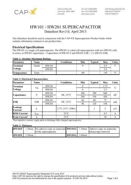
<strong>HW101</strong> / <strong>HW201</strong> SUPERCAPACITOR<br />
Datasheet Re<strong>v3.0</strong>, April 2013<br />
This Datasheet should be read in conjunction with the CAP-<strong>XX</strong> Supercapacitors Product Guide which<br />
contains information common to our product lines.<br />
Electrical Specifications<br />
The <strong>HW101</strong> is a single cell supercapacitor. The <strong>HW201</strong> is a dual cell supercapacitor with two <strong>HW101</strong> cells<br />
in series, so <strong>HW201</strong> capacitance = <strong>Cap</strong>acitance of <strong>HW101</strong>/2 and <strong>HW201</strong> ESR = 2 x <strong>HW101</strong> ESR.<br />
Table 1: Absolute Maximum Ratings<br />
Parameter Name Conditions Min Typical Max Units<br />
Terminal<br />
Voltage<br />
Vpeak <strong>HW101</strong> 0 2.9 V<br />
<strong>HW201</strong> 5.8<br />
Temperature Tmax -40 +85 °C<br />
Table 2: Electrical Characteristics<br />
Parameter Name Conditions Min Typical Max Units<br />
Terminal<br />
Voltage<br />
<strong>Cap</strong>acitance<br />
ESR<br />
Vn<br />
C<br />
ESR<br />
<strong>HW101</strong> 0 2.75<br />
<strong>HW201</strong> 0 5.5<br />
<strong>HW101</strong><br />
560 700 840<br />
DC, 23°C<br />
<strong>HW201</strong> 280 350 420<br />
<strong>HW101</strong><br />
48 60 72<br />
DC, 23°C<br />
<strong>HW201</strong> 96 120 144<br />
Leakage<br />
Current<br />
I L 2.7V, 23°C 120hrs 1 2 µA<br />
RMS Current I RMS 23°C 4.5 A<br />
Peak Current 1 I P 23°C 30 A<br />
1 Non-repetitive current, single pulse to discharge fully charged supercapacitor.<br />
Table 3: Thickness<br />
<strong>HW101</strong>F 1.20mm No adhesive tape on underside<br />
of the supercapacitor<br />
<strong>HW101</strong>G<br />
<strong>HW201</strong>F 2.50mm <strong>HW201</strong>G 2.60mm<br />
V<br />
mF<br />
m<br />
1.30mm Adhesive tape on underside,<br />
release tape removed<br />
________________________________________________________________________________________________<br />
<strong>HW101</strong> <strong>HW201</strong> Supercapacitor Datasheet V3.0 June 2013<br />
Note: CAP-<strong>XX</strong> reserves the right to change the specification of its products and any data without notice.<br />
CAP-<strong>XX</strong> products are not authorised for use in life support systems. © CAP-<strong>XX</strong> 2013 Page 1 of 8
Definition of Terms<br />
In its simplest form, the Equivalent Series Resistance (ESR) of a capacitor is the real part of the complex<br />
impedance. In the time domain, it can be found by applying a step discharge current to a charged cell as in<br />
Fig. 1. In this figure, the supercapacitor is pre-charged and then discharged with a current pulse, I =1A for<br />
duration 0.01 sec.<br />
Figure 1: Effective capacitance, instantaneous capacitance and ESR for an <strong>HW201</strong><br />
The ESR is found by dividing the instantaneous voltage step (∆V) by I. In this example = (4.985V-<br />
4.87V)/1.02A = 112.7mΩ.<br />
The instantaneous capacitance (C i ) can be found by taking the inverse of the derivative of the voltage, and<br />
multiplying it by I.<br />
The effective capacitance for a pulse of duration t n , Ce(t n ) is found by dividing the total charge removed<br />
from the capacitor (∆Q n ) by the voltage lost by the capacitor (∆V n ). For constant current Ce(t n ) = I x<br />
t n /V n . Ce increases as the pulse width increases and tends to the DC capacitance value as the pulse width<br />
becomes very long (~10 secs). After 2msecs, Fig 1 shows the voltage drop V 2ms = (4.87 V – 4.753V) =<br />
117mV. Therefore Ce(2ms) = 1.02A x 2ms/117mV = 17.4mF. After 10ms, the voltage drop = 4.87 V –<br />
4.61V = 260mV. Therefore Ce(10ms) = 1.02 A x 10ms/260mV =39.2mF. The DC capacitance of an <strong>HW201</strong><br />
= 350 mF. Note that ∆V, or IR drop, is not included because very little charge is removed from the capacitor<br />
during this time. Ce shows the time response of the capacitor and it is useful for predicting circuit behavior in<br />
pulsed applications. Use the Ce for your pulsewidth to calculate<br />
________________________________________________________________________________________________<br />
<strong>HW101</strong> <strong>HW201</strong> Supercapacitor Datasheet V3.0 June 2013<br />
Note: CAP-<strong>XX</strong> reserves the right to change the specification of its products and any data without notice.<br />
CAP-<strong>XX</strong> products are not authorised for use in life support systems. © CAP-<strong>XX</strong> 2013 Page 2 of 8
Measurement of DC <strong>Cap</strong>acitance<br />
Fig 2: Measurement of DC <strong>Cap</strong>acitance for an <strong>HW201</strong><br />
Fig 2 shows the measurement of DC capacitance by drawing a constant 100mA current from a fully charged<br />
supercapacitor and measuring the time taken to discharge from 1.5V to 0.5V for a single cell, or from 3V to<br />
1V for a dual cell supercapacitor. In this case, C = 0.1A x 6.872s /2V = 0.344F, which is well within the<br />
350mF +/- 20% tolerance for an <strong>HW201</strong> cell.<br />
Measurement of ESR<br />
Fig 3: Measurement of ESR for an <strong>HW201</strong><br />
Fig 3 shows DC measurement of ESR by applying a step load current to the supercapacitor and measuring<br />
the resulting voltage drop. CAP-<strong>XX</strong> waits for a delay of 50µs after the step current is applied to ensure the<br />
voltage and current have settled. In this case the ESR is measured as 109mV/1.03A = 105.8mΩ.<br />
________________________________________________________________________________________________<br />
<strong>HW101</strong> <strong>HW201</strong> Supercapacitor Datasheet V3.0 June 2013<br />
Note: CAP-<strong>XX</strong> reserves the right to change the specification of its products and any data without notice.<br />
CAP-<strong>XX</strong> products are not authorised for use in life support systems. © CAP-<strong>XX</strong> 2013 Page 3 of 8
Effective <strong>Cap</strong>acitance<br />
Figure 4: Effective <strong>Cap</strong>acitance<br />
Fig 4 shows the effective capacitance for the <strong>HW101</strong>, <strong>HW201</strong> @ 23°C. This shows that for a 1msec PW,<br />
you will measure 8% of DC capacitance or 56mF for an <strong>HW101</strong> or 28mF for an <strong>HW201</strong>. At 10msecs you<br />
will measure 25% of the DC capacitance, and at 100msecs you will measure 60% of DC capacitance.<br />
Ceffective is a time domain representation of the supercapacitor's frequency response. If, for example, you<br />
were calculating the voltage drop if the supercapacitor was supporting 1A for 10msecs, then you would use<br />
the Ceff(10msecs) = 25% of DC capacitance = 87.5mF for an <strong>HW201</strong>, so Vdrop = 1A x ESR + 1A x<br />
duration/C = 1A x 120mΩ + 1A x 10ms / 87.5mF = 234.3mV. The next section on pulse response shows<br />
how the effective capacitance is sufficient for even short pulse widths.<br />
Pulse Response<br />
Fig 5 shows that the <strong>HW201</strong><br />
supercapacitor does an<br />
excellent job supporting a<br />
GPRS class 10 pulse train,<br />
drawing 1.8A for 1.1ms at<br />
25% duty cycle. The source is<br />
current limited to 0.6A and<br />
the supercapacitor provides<br />
the 1.2A difference to achieve<br />
the peak current. At first<br />
glance the freq response of<br />
Fig 8 indicates the<br />
supercapacacitor would not<br />
support a 1ms pulse, but the<br />
Ceff of 28mF coupled with<br />
the low ESR supports this<br />
pulse train with only ~240mV<br />
droop in the supply rail.<br />
Fig 5: <strong>HW201</strong> Pulse Response with GPRS Class 10 Pulse Train<br />
________________________________________________________________________________________________<br />
<strong>HW101</strong> <strong>HW201</strong> Supercapacitor Datasheet V3.0 June 2013<br />
Note: CAP-<strong>XX</strong> reserves the right to change the specification of its products and any data without notice.<br />
CAP-<strong>XX</strong> products are not authorised for use in life support systems. © CAP-<strong>XX</strong> 2013 Page 4 of 8
DC <strong>Cap</strong>acitance variation with temperature<br />
Figure 6: <strong>Cap</strong>acitance change with temperature<br />
Fig 6 shows that DC capacitance is approximately constant with temperature.<br />
ESR variation with temperature<br />
Figure 7: ESR change with temperature<br />
Fig 7 shows that ESR at -40°C is ~3.5 x ESR at room temp, and that ESR at 70ºC is ~0.9 x ESR at room<br />
temperature.<br />
________________________________________________________________________________________________<br />
<strong>HW101</strong> <strong>HW201</strong> Supercapacitor Datasheet V3.0 June 2013<br />
Note: CAP-<strong>XX</strong> reserves the right to change the specification of its products and any data without notice.<br />
CAP-<strong>XX</strong> products are not authorised for use in life support systems. © CAP-<strong>XX</strong> 2013 Page 5 of 8
Frequency Response<br />
Fig 8: Frequency Response of Impedance (biased at 2.5V with a 50mV test signal)<br />
Fig 9: Frequency Response of ESR, <strong>Cap</strong>acitance & Inductance<br />
Fig 8 shows the supercapacitor behaves as an ideal capacitor until approx 2 Hz when the magnitude no<br />
longer rolls off proportionally to 1/freq and the phase crosses -45°. Performance of supercapacitors with<br />
frequency is complex and the best predictor of performance is Fig 4 showing effective capacitance as a<br />
function of pulsewidth.<br />
________________________________________________________________________________________________<br />
<strong>HW101</strong> <strong>HW201</strong> Supercapacitor Datasheet V3.0 June 2013<br />
Note: CAP-<strong>XX</strong> reserves the right to change the specification of its products and any data without notice.<br />
CAP-<strong>XX</strong> products are not authorised for use in life support systems. © CAP-<strong>XX</strong> 2013 Page 6 of 8
Leakage Current<br />
Fig 10: Leakage Current<br />
Fig 10 shows the leakage current for <strong>HW101</strong> at room temperature. The leakage current decays over time, and<br />
the equilibrium value leakage current will be reached after ~120hrs at room temperature. The typical<br />
equilibrium leakage current is 2µA at room temperature. At 70°C leakage current will be ~5µA.<br />
Charge Current<br />
Fig 11: Charging an <strong>HW101</strong> with low current<br />
The corollary to the slow decay in leakage currents shown in Fig 10 is that charging a supercapacitor at very<br />
low currents takes longer than theory predicts. At higher charge currents, the charge rate is as theory predicts.<br />
For example, it should take 0.7F x 2.2V / 0.00002A = 21.3hrs to charge a 0.7 F supercapacitor to 2.2V at<br />
20µA, but Fig 11 shows it took 58hrs. At 200µA charging occurs at a rate close to the theoretical rate.<br />
________________________________________________________________________________________________<br />
<strong>HW101</strong> <strong>HW201</strong> Supercapacitor Datasheet V3.0 June 2013<br />
Note: CAP-<strong>XX</strong> reserves the right to change the specification of its products and any data without notice.<br />
CAP-<strong>XX</strong> products are not authorised for use in life support systems. © CAP-<strong>XX</strong> 2013 Page 7 of 8
RMS Current<br />
Fig 12: Temperature rise in <strong>HW201</strong> with RMS current<br />
Continuous current flow into/out of the supercap will cause self heating, which limits the maximum<br />
continuous current the supercapacitor can handle. This is measured by a current square wave with 50% duty<br />
cycle, charging the supercapacitor to rated voltage at a constant current, then discharging the supercapacitor<br />
to half rated voltage at the same constant current value. For a square wave with 50% duty cycle, the RMS<br />
current is the same as the current amplitude. Fig 12 shows the increase in temperature as a function of RMS<br />
current. From this, the maximum RMS current in an application can be calculated, for example, if the<br />
ambient temperature is 40C, and the maximum desired temperature for the supercapacitor is 70C, then the<br />
maximum RMS current should be limited to 3.5A, which causes a 30C temperature increase.<br />
CAP-<strong>XX</strong> Supercapacitors Product Guide<br />
Refer to the package drawings in the CAP-<strong>XX</strong> Supercapacitors Product Guide for detailed information of the<br />
product’s dimensions, PCB landing placements, active areas and electrical connections.<br />
Refer to the CAP-<strong>XX</strong> Supercapacitors Product Guide for information on endurance and shelf life,<br />
transportation and storage, assembly and soldering, safety and RoHS/EREACH certification.<br />
________________________________________________________________________________________________<br />
<strong>HW101</strong> <strong>HW201</strong> Supercapacitor Datasheet V3.0 June 2013<br />
Note: CAP-<strong>XX</strong> reserves the right to change the specification of its products and any data without notice.<br />
CAP-<strong>XX</strong> products are not authorised for use in life support systems. © CAP-<strong>XX</strong> 2013 Page 8 of 8