Automated Generation of Kempe Linkages for ... - Alexander Kobel
Automated Generation of Kempe Linkages for ... - Alexander Kobel
Automated Generation of Kempe Linkages for ... - Alexander Kobel
You also want an ePaper? Increase the reach of your titles
YUMPU automatically turns print PDFs into web optimized ePapers that Google loves.
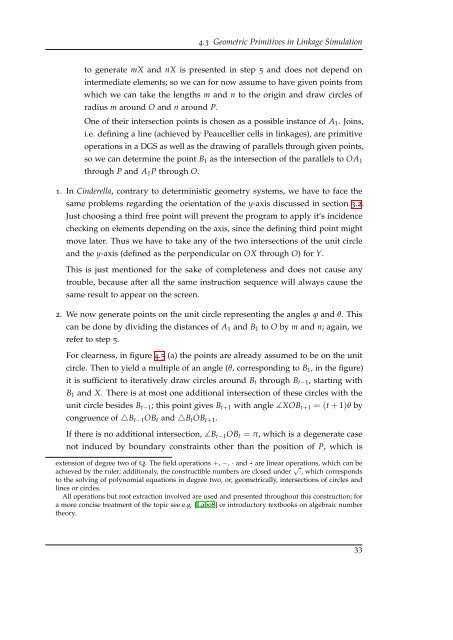
4.3 Geometric Primitives in Linkage Simulation<br />
to generate mX and nX is presented in step 5 and does not depend on<br />
intermediate elements; so we can <strong>for</strong> now assume to have given points from<br />
which we can take the lengths m and n to the origin and draw circles <strong>of</strong><br />
radius m around O and n around P.<br />
One <strong>of</strong> their intersection points is chosen as a possible instance <strong>of</strong> A 1 . Joins,<br />
i.e. defining a line (achieved by Peaucellier cells in linkages), are primitive<br />
operations in a DGS as well as the drawing <strong>of</strong> parallels through given points,<br />
so we can determine the point B 1 as the intersection <strong>of</strong> the parallels to OA 1<br />
through P and A 1 P through O.<br />
1. In Cinderella, contrary to deterministic geometry systems, we have to face the<br />
same problems regarding the orientation <strong>of</strong> the y-axis discussed in section 3.2.<br />
Just choosing a third free point will prevent the program to apply it‘s incidence<br />
checking on elements depending on the axis, since the defining third point might<br />
move later. Thus we have to take any <strong>of</strong> the two intersections <strong>of</strong> the unit circle<br />
and the y-axis (defined as the perpendicular on OX through O) <strong>for</strong> Y.<br />
This is just mentioned <strong>for</strong> the sake <strong>of</strong> completeness and does not cause any<br />
trouble, because after all the same instruction sequence will always cause the<br />
same result to appear on the screen.<br />
2. We now generate points on the unit circle representing the angles ϕ and θ. This<br />
can be done by dividing the distances <strong>of</strong> A 1 and B 1 to O by m and n; again, we<br />
refer to step 5.<br />
For clearness, in figure 4.5 (a) the points are already assumed to be on the unit<br />
circle. Then to yield a multiple <strong>of</strong> an angle (θ, corresponding to B 1 , in the figure)<br />
it is sufficient to iteratively draw circles around B t through B t−1 , starting with<br />
B 1 and X. There is at most one additional intersection <strong>of</strong> these circles with the<br />
unit circle besides B t−1 ; this point gives B t+1 with angle ∡XOB t+1 = (t + 1)θ by<br />
congruence <strong>of</strong> △B t−1 OB t and △B t OB t+1 .<br />
If there is no additional intersection, ∡B t−1 OB t = π, which is a degenerate case<br />
not induced by boundary constraints other than the position <strong>of</strong> P, which is<br />
extension <strong>of</strong> degree two <strong>of</strong> Q. The field operations +, −, · and ·· are linear operations, which can be<br />
achieved by the ruler; additionaly, the constructible numbers are closed under √·, which corresponds<br />
to the solving <strong>of</strong> polynomial equations in degree two, or, geometrically, intersections <strong>of</strong> circles and<br />
lines or circles.<br />
All operations but root extraction involved are used and presented throughout this construction; <strong>for</strong><br />
a more concise treatment <strong>of</strong> the topic see e.g. [Lab08] or introductory textbooks on algebraic number<br />
theory.<br />
33


