

Pressure reducing valve - Caleffi
Pressure reducing valve - Caleffi
Pressure reducing valve - Caleffi

You also want an ePaper? Increase the reach of your titles
YUMPU automatically turns print PDFs into web optimized ePapers that Google loves.
<strong>Pressure</strong> <strong>reducing</strong> <strong>valve</strong><br />
576 series<br />
Technical specifications<br />
Materials<br />
Body and cover: cast iron EN-GJS-450-10<br />
Diaphragm: cloth covered elastomer - CR<br />
Obturator: PUR<br />
Obturator seat: stainless steel<br />
Corrosion-resistant epoxy coating suitable for contact with drinking<br />
water.<br />
Performance<br />
Max. upstream pressure: 16 bar<br />
Downstream pressure setting range: 1,5–6 bar<br />
on request 6–12 bar<br />
Max. working temperature: 65°C<br />
<strong>Pressure</strong> gauge scale: 0–16 bar<br />
Connections<br />
Flanged connections: DN 80–DN 150 (DN 200 on request)<br />
Coupling with counterflange EN 1092-1 DN 80–DN 150, PN 16;<br />
DN 200, PN 10<br />
Face-to-face gage according to ISO 5752 series 1<br />
REGI STERED BS EN ISO 9001:2008<br />
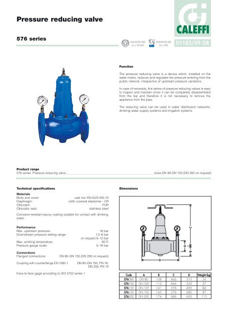
Function<br />
CALEFFI<br />
01183/09 GB<br />
The pressure <strong>reducing</strong> <strong>valve</strong> is a device which, installed on the<br />
water mains, reduces and regulates the pressure entering from the<br />
public network, irrespective of upstream pressure variations.<br />
In case of necessity, this series of pressure <strong>reducing</strong> <strong>valve</strong>s is easy<br />
to inspect and maintain since it can be completely disassembled<br />
from the top and therefore it is not necessary to remove the<br />
appliance from the pipe.<br />
The <strong>reducing</strong> <strong>valve</strong> can be used in water distribution networks,<br />
drinking water supply systems and irrigation systems.<br />
Dimensions<br />
Code<br />
576080<br />
576100<br />
576120<br />
576150<br />
576200<br />
Cert. n° FM 21654<br />
1<br />
0<br />
2<br />
CALEFFI<br />
bar<br />
A<br />
DN 80<br />
DN 100<br />
DN 125<br />
DN 150<br />
DN 200<br />
3<br />
4<br />
UNI EN ISO 9001:2000<br />
Cert. n° 0003<br />
Product range<br />
576 series <strong>Pressure</strong> <strong>reducing</strong> <strong>valve</strong> sizes DN 80-DN 150 (DN 200 on request)<br />
D<br />
B<br />
108<br />
112<br />
141<br />
145<br />
174<br />
2<br />
1<br />
3<br />
0<br />
4<br />
CALEFFI<br />
bar<br />
C<br />
466<br />
466<br />
576<br />
576<br />
686<br />
A<br />
C<br />
B<br />
D<br />
310<br />
350<br />
400<br />
480<br />
600<br />
Weight (kg)<br />
34<br />
37<br />
84<br />
87<br />
115
Operating principle<br />
The operating principle of the pressure <strong>reducing</strong> <strong>valve</strong> is based on<br />
the balance between two opposing forces: the thrust exerted by the<br />
downstream pressure on the lower part of the mobile <strong>valve</strong> is<br />
counteracted by the adjustable compression force of the spring.<br />
Since the active surface of the diaphragm is equivalent to the active<br />
surface of the mobile <strong>valve</strong>, the thrust which the upstream pressure<br />
exerts on the lower part of the diaphragm is compensated by the<br />
thrust exerted on the upper part of the mobile <strong>valve</strong>, thus rendering<br />
the appliance insensitive to changes in upstream pressure.<br />
When the pressure downstream of the <strong>reducing</strong> <strong>valve</strong> becomes<br />
lower than the regulating pressure, the force exerted by the spring<br />
becomes predominant and the obturator opens, increasing the<br />
degree of opening to increase the flow rate and restore the<br />
pressure (Fig. 1). However when the downstream pressure<br />
increases, the obturator closes, <strong>reducing</strong> the degree of opening to<br />
limit the flow rate. The downstream pressure therefore remains<br />
constant.<br />
1<br />
0<br />
2<br />
CALEFFI<br />
bar<br />
3<br />
4<br />
UPSTREAM DOWNSTREAM<br />
Fig.1<br />
Hydraulic characteristics<br />
1<br />
0<br />
2<br />
CALEFFI<br />
bar<br />
The following cavitation diagram can be used to check the<br />
operating conditions of the pressure <strong>reducing</strong> <strong>valve</strong>:<br />
Upstream pressure (bar)<br />
Downstream pressure (bar)<br />
3<br />
4<br />
Characteristic components<br />
11 Body<br />
12 Stem<br />
13 Seat<br />
14 Cover<br />
15 Lower cylinder<br />
16 Obturator holder<br />
17 Obturator stop<br />
18 Flange<br />
19 Mounting plate<br />
10 Guide cylinder<br />
11 Guide beat<br />
12 Adjustment spring<br />
18<br />
2<br />
17<br />
8<br />
15<br />
13<br />
7<br />
14<br />
6<br />
1<br />
0<br />
2<br />
CALEFFI<br />
bar<br />
3<br />
4<br />
13 Diaphragm<br />
14 Mobile <strong>valve</strong><br />
15 Guide ring<br />
16 Lower cylinder O-ring<br />
17 Non-removable nut<br />
18 Nut<br />
19 Cover fixing nut<br />
20 Setting screw<br />
21 Adjustment key<br />
22 <strong>Pressure</strong> gauge<br />
23 <strong>Pressure</strong> gauge cock<br />
Zone 1 : normal operating conditions<br />
Zone 2 : cavitation zone (use not recommended)<br />
Zone 3 : impossible<br />
Sizing<br />
The diameter of the appliance must be chosen based on the<br />
maximum flow rate and the conditions of use and not according the<br />
diameter of the pipe.<br />
The maximum flow rate is calculated considering an average<br />
velocity in the inflow section of 1,5 m/s.<br />
1<br />
0<br />
2<br />
CALEFFI<br />
bar<br />
DN 80 100 125 150 200<br />
Max. recommended<br />
flow rate (l/s)<br />
3<br />
4<br />
21<br />
20<br />
4<br />
9<br />
12<br />
22<br />
10<br />
23<br />
19<br />
16<br />
5<br />
3<br />
1<br />
11<br />
7,5 11,8 18,4 26,5 47,2
Installation<br />
1. Before the installation, open all distribution taps to clean out the<br />
system and to expel air remaining in the pipes.<br />
2. Install the shut-off <strong>valve</strong>s upstream and downstream to facilitate<br />
future maintenance.<br />
3. The <strong>reducing</strong> <strong>valve</strong> can be installed in any position.<br />
4. Close the downstream shut-off <strong>valve</strong>.<br />
5. Calibrate the device using the special key, turning it clockwise to<br />
increase the value and anticlockwise to decrease it.<br />
6. Read the desired value on the downstream pressure gauge.<br />
Installation recommendations<br />
Water hammer is one of the major causes of breakage in pressure<br />
<strong>reducing</strong> <strong>valve</strong>s. Consequently during installation in high-risk<br />
systems, it is advisable to fit suitable devices to absorb water<br />
hammer.<br />
Functional faults<br />
1<br />
0<br />
2<br />
CALEFFI<br />
bar<br />
2<br />
3<br />
4<br />
1<br />
0<br />
2<br />
3<br />
3<br />
1<br />
4<br />
3<br />
4<br />
4<br />
0<br />
CALEFFI<br />
bar<br />
CALEFFI<br />
bar<br />
CALEFFI<br />
bar<br />
2<br />
0<br />
1<br />
The <strong>reducing</strong> <strong>valve</strong> does not maintain the set value<br />
In the majority of cases, this problem is due to impurities depositing<br />
on the seat seal and causing seepage and creeping, thereby<br />
increasing downstream pressure.<br />
The solution is to install a filter downstream of the <strong>valve</strong> and to<br />
ensure that maintenance is properly carried out (see maintenance<br />
section).<br />
2<br />
1<br />
3<br />
0<br />
4<br />
CALEFFI<br />
bar<br />
4<br />
3<br />
CALEFFI<br />
bar<br />
2<br />
0<br />
1<br />
Maintenance<br />
When performing maintenance it is not necessary to remove the<br />
appliance from the pipe.<br />
1. Isolate the appliance by closing the shut-off <strong>valve</strong>s.<br />
2. Unscrew the setting screw (20) in an anticlockwise direction until<br />
it is completely removed, diagram A.<br />
3. Unscrew the nuts and remove the cover (4). Extract the mounting<br />
plate (9) and the spring (12).<br />
4. Disengage the diaphragm (13) from the pins. With the adjustment<br />
key (21) positioned as indicated in diagram B unscrew the nut (18)<br />
with a plate wrench.<br />
5. Remove the flange (8), the diaphragm (13), the obturator stop (7)<br />
and the lower cylinder (5).<br />
6. To unscrew the seat (3) use the up-side down turned cover as<br />
shown in diagram C.<br />
7. After having removed the seat, extract the obturator holder (6)<br />
and the gasket (20) using the stem (2).<br />
NOTE: If necessary, the obturator gasket can be changed without<br />
removing the seat. Check that it is correctly refitted.<br />
A<br />
B<br />
C<br />
1<br />
0<br />
2<br />
CALEFFI<br />
bar<br />
1<br />
0<br />
1<br />
0<br />
2<br />
3<br />
4<br />
CALEFFI<br />
bar<br />
2<br />
CALEFFI<br />
bar<br />
3<br />
4<br />
3<br />
4<br />
12<br />
20<br />
8<br />
5<br />
9<br />
4<br />
13<br />
5<br />
7<br />
2<br />
18<br />
3<br />
20<br />
2 6<br />
1<br />
0<br />
21<br />
2<br />
CALEFFI<br />
bar<br />
1<br />
0<br />
1<br />
0<br />
2<br />
3<br />
4<br />
CALEFFI<br />
bar<br />
2<br />
CALEFFI<br />
bar<br />
3<br />
4<br />
3<br />
4
SPECIFICATION SUMMARY<br />
576 series<br />
<strong>Pressure</strong> <strong>reducing</strong> <strong>valve</strong> with compensated seat. Flanged connections DN 80 (from DN 80 to DN 150, PN 16; DN 200 PN 10).<br />
Cast iron body. Stainless steel seat. Diaphragm in cloth covered elastomer - CR, obturator in PUR. Maximum working<br />
temperature 65°C. Maximum upstream pressure 16 bar. Downstream pressure setting range from 1,5 to 6 bar, on request<br />
from 6 to 12 bar. Supplied with double pressure gauge 0–16 bar upstream and downstream. Corrosion-resistant epoxy<br />
coating for contact with drinking water. Diaphragm, seat and obturator removable for maintenance purposes.<br />
We reserve the right to change our products and their relevant technical data, contained in this publication, at any time and without prior notice.<br />
CALEFFI<br />
CALEFFI S.P.A. · S.R.229, N.25 · 28010 FONTANETO D’AGOGNA (NO) · ITALY · TEL. +39 0322 8491 · FAX +39 0322 863723<br />
· www.caleffi.com · info@caleffi.com ·<br />
© Copyright 2009 <strong>Caleffi</strong>


