

Radio wave temperature control systems - Caleffi
Radio wave temperature control systems - Caleffi
Radio wave temperature control systems - Caleffi

Create successful ePaper yourself
Turn your PDF publications into a flip-book with our unique Google optimized e-Paper software.
<strong>Radio</strong> <strong>wave</strong> <strong>temperature</strong> <strong>control</strong><br />
<strong>systems</strong><br />
740 series<br />
Product range<br />
740 series <strong>Radio</strong> <strong>wave</strong> <strong>temperature</strong> <strong>control</strong><br />
740000 code <strong>Radio</strong> chrono-thermostat<br />
740201 code <strong>Radio</strong> thermostat<br />
740100 code Wall-mounting receiver 1 channel<br />
740101 code Concealed receiver 1 channel<br />
740104 code Wall-mounting receiver 2 channels<br />
740202 code Wall-mounting receiver 8 channels<br />
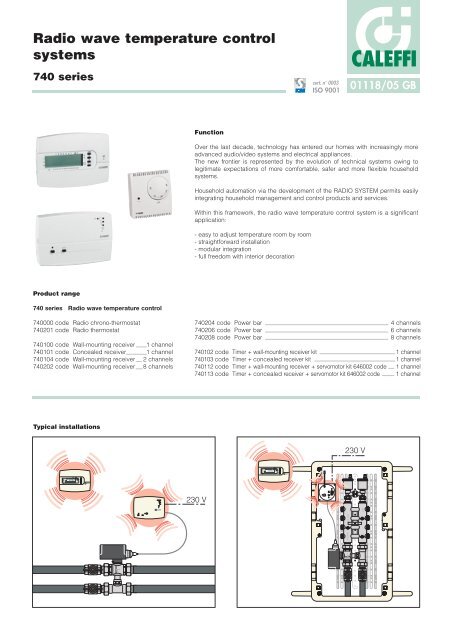
Typical installations<br />
1 2 3 4 5 6<br />
t1/t2/t<br />
t1<br />
ON OFF<br />
H O 2<br />
t2<br />
t3 - t1<br />
- t2<br />
0 2 4 6 8 10 12 14 16 18 20 22<br />
CALEFFI<br />
1<br />
RESET<br />
ON 230<br />
CALEFFI<br />
ON<br />
Function<br />
cert. n° 0003<br />
ISO 9001<br />
01118/05 GB<br />
Over the last decade, technology has entered our homes with increasingly more<br />
advanced audio/video <strong>systems</strong> and electrical appliances.<br />
The new frontier is represented by the evolution of technical <strong>systems</strong> owing to<br />
legitimate expectations of more comfortable, safer and more flexible household<br />
<strong>systems</strong>.<br />
Household automation via the development of the RADIO SYSTEM permits easily<br />
integrating household management and <strong>control</strong> products and services.<br />
Within this framework, the radio <strong>wave</strong> <strong>temperature</strong> <strong>control</strong> system is a significant<br />
application:<br />
- easy to adjust <strong>temperature</strong> room by room<br />
- straightforward installation<br />
- modular integration<br />
- full freedom with interior decoration<br />
CALEFFI<br />
740204 code Power bar 4 channels<br />
740206 code Power bar 6 channels<br />
740208 code Power bar 8 channels<br />
740102 code Timer + wall-mounting receiver kit 1 channel<br />
740103 code Timer + concealed receiver kit 1 channel<br />
740112 code Timer + wall-mounting receiver + servomotor kit 646002 code 1 channel<br />
740113 code Timer + concealed receiver + servomotor kit 646002 code 1 channel<br />
V<br />
1 2 3 4 5 6<br />
t1/t2/t<br />
t1<br />
ON OFF<br />
H O 2<br />
t2<br />
t3 - t1<br />
- t2<br />
0 2 4 6 8 10 12 14 16 18 20 22<br />
CALEFFI<br />
ON<br />
RESET<br />
230 V<br />
Mod. Dep.<br />
CALEFFI<br />
356
Technical specifications<br />
Weekly digital chrono-thermostat with radio transmitter<br />
(740000 code)<br />
Power supply: 2 x 1,5 V alkaline penlight<br />
Operating time: 1 year<br />
Frequency: 868,35 MHz<br />
Maximum range in free air: 120 m<br />
Antenna: integrated<br />
Contact capacity: 5 (2) A / 250 V<br />
Installation: wall mounting<br />
Protection rating: IP 30<br />
Insulation class: III<br />
Control input for telephone programmer code 739000<br />
Temperature levels: 2 + antifreeze<br />
Reference standards: LVD EN 60 730-1<br />
EMC EN 301 489-3<br />
RADIO EN 300 220-3<br />
Wall-mounting receiver: 1 channel (740100 code)<br />
2 channels (740104 code)<br />
Power supply: 230 V - 50-60 Hz<br />
Contact capacity: 5 (2) A / 250 V<br />
Output type: free contact on switching<br />
Reception frequency: 868,35 MHz<br />
Protection rating: IP 30<br />
Insulation class: II<br />
Maximum range in free air: 130 m<br />
Reference standards: LVD EN 60 730-1<br />
EMC EN 301 489-3<br />
RADIO EN 300 220-3<br />
Recess-mounting receiver<br />
for plastic consumer box: 1 channel (740101 code)<br />
Power supply: 230 V - 50-60 Hz<br />
Contact capacity: 5 (2) A / 250 V<br />
Output type: N/O free contact<br />
Protection rating: IP 30<br />
Insulation class: II<br />
Maximum range in free air: max 120 m<br />
Thermostat with radio transmitter (740201 code)<br />
Power supply: 2 x 1,5 V alkaline penlight<br />
Operating time: 1 year<br />
Frequency: 868,35 MHz<br />
Maximum range in free air: 130 m<br />
Operation: ON/OFF with differential that can be set from 0,3°C to 0,6°C<br />
Protection rating: IP 30<br />
8-channel wall-mounting receiver (740202 code)<br />
Power supply: 18 V (via <strong>control</strong> bar)<br />
Input: 1 VA<br />
Max bus length: 100 m (2 x 0,5 mm2 )<br />
Reception frequency: 868,35 MHz<br />
Signal range in free air: max 120 m<br />
Protection rating: IP 30<br />
Insulation class: II<br />
t1<br />
ON OFF<br />
t2<br />
H O 2<br />
t❄ - t1<br />
- t2<br />
t1/t2/t<br />
CALEFFI<br />
Dimensions:<br />
120 x 80 x 18 mm<br />
Programming: minimum 30 min<br />
Manual function - Temporary function - Receiver coupling test function<br />
- ON/OFF operation with adjustable differential from 0,2 to 0,7°C.<br />
ON<br />
1<br />
CALEFFI<br />
1 2 3 4 5 6<br />
0 2 4 6 8 10 12 14 16 18 20 22<br />
ON<br />
RESET<br />
RESET<br />
ON<br />
ON<br />
CALEFFI<br />
1 2 3 4 5 6 7 8 RESET<br />
CALEFFI<br />
Dimensions:<br />
132 x 90 x 25 mm<br />
Dimensions:<br />
60 x 60 x 44 mm<br />
Dimensions:<br />
76 x 81 x 40 mm<br />
Dimensions:<br />
132 x 90 x 25 mm
Power bar: 4 outputs + aux (740204 code)<br />
6 outputs + aux (740206 code)<br />
8 outputs + aux (740208 code)<br />
Power supply: 230 V - 50-60 Hz<br />
Input: 5,5 VA maximum (8 outputs)<br />
Output type: relay with single-pole switchover contact<br />
- Polarized N/O-N/C - 8 (2) A / 250 V<br />
Auxiliary output type: relay with single-pole switchover contact<br />
potential-free N/O-N/C-COM - 8 (2) A / 250 V<br />
Maximum total load 8 outputs: 16 A<br />
Protection rating: IP 52 (with rubber cable clamps)<br />
Insulation class: II<br />
Reference standards: LVD EN 60 730-1<br />
EMC EN 301 489-3<br />
RADIO EN 300 220-3<br />
Operational/functional characteristics<br />
Relay output<br />
Each relay output of the power bar has a double switchover.<br />
It is therefore possible to pilot both a two-wire and a 3-wire generic<br />
valve.<br />
- PUMP CONTROL<br />
The pump <strong>control</strong> permits starting up the pump when there is an<br />
active channel (zone) and stopping the pump when all the channels<br />
are OFF.<br />
Since thermo-electric actuators, characterised by a starting lag<br />
(delay), are often installed, pump starting can be programmed in<br />
the receiver as:<br />
R - Delayed (120 s)<br />
or<br />
I - Instantaneous<br />
FRONT PANEL OF 8-CHANNEL RECEIVER<br />
ON<br />
N<br />
L<br />
ON - Power on<br />
- 3-level bus signal indicator lights<br />
1 2 3 4 5 6 7 8 RESET<br />
Channel status LED<br />
Keys for manual channel overside<br />
Configuration RESET key<br />
Pump status LED<br />
1 2 3 4<br />
Dimensions:<br />
250 x 43 x 76 mm<br />
Master function<br />
1<br />
The MASTER function is the authority of a <strong>temperature</strong> <strong>control</strong><br />
device to define periods of attenuation for itself and for the other<br />
devices (slaves) associated with it.<br />
The MASTER function can be performed only by the radio<br />
chrono-thermostat (740000 code).<br />
It is nevertheless possible to combine more than one master in a<br />
<strong>temperature</strong> <strong>control</strong> system.<br />
The decision to have a <strong>temperature</strong> <strong>control</strong> system with a number<br />
of master chrono-thermostats that interact with the 8-channel<br />
receiver may be made in order to have 2 or more entirely separate<br />
and independent zones as regards both time and <strong>temperature</strong><br />
levels.<br />
After making this first distinction, the other <strong>temperature</strong> <strong>control</strong><br />
devices can, in the self-learning phase, be associated with a<br />
specific master or remain completely independent.<br />
All the devices associated in the learning phase are independent in<br />
comfort operation as regards their <strong>temperature</strong> settings. The<br />
<strong>temperature</strong> setting can be selected on the thermostat knob.<br />
During attenuation, <strong>control</strong>led by the master chrono-thermostat with<br />
its clock function, the crossed devices check that the attenuation<br />
setting selected on the master chrono-thermostat is observed.<br />
Lastly, all the devices (thermostats and chrono-thermostats too)<br />
that are not combined with a master device act independently<br />
according to their <strong>temperature</strong> settings.<br />
The association criterion must follow the proper path:<br />
<strong>temperature</strong> <strong>control</strong> device<br />
receiver<br />
<strong>control</strong> bar<br />
valve servo<strong>control</strong><br />
2<br />
3<br />
In this connection it is possible, on the front of the receiver, to pin<br />
the combined service channel by channel.<br />
4<br />
1 - LED Power supply 230 V present<br />
2 - LED Bus fault<br />
3 - LED 1÷8 Channel status<br />
4 - LED Pump status<br />
5<br />
6<br />
7<br />
8
<strong>Radio</strong> <strong>systems</strong> - architecture<br />
The modularity and ease of transmitter/receiver coupling make various operational architectures possible.<br />
The modular implementation makes it easy, even in the future, to add on new <strong>temperature</strong> <strong>control</strong> devices.<br />
All this is possible until the capacities of the receiver and differentiated outputs (power bar relay) are fully saturated.<br />
The following suggestions are by no means exhaustive.<br />
1) Temperature <strong>control</strong> of a single zone (consumer plumbing boxes made of metal).<br />
740000 code 740100 code<br />
2) Temperature <strong>control</strong>s of a single zone (consumer plumbing box made of plastic).<br />
740000 code<br />
1 2 3 4 5 6<br />
t1<br />
ON OFF<br />
H O 2<br />
t2<br />
t3 - t1<br />
- t2<br />
0 2 4 6 8 10 12 14 16 18 20 22<br />
t1/t2/t<br />
CALEFFI<br />
740101 code<br />
ON<br />
RESET<br />
230 V<br />
356<br />
Mod. Dep.<br />
Mod. Dep.<br />
356<br />
Receiver terminal board<br />
The distinction between wall-mounting receiver (740100 code) and concealed receiver (740101 code) depends on the type of material<br />
(metal - plastic) of the plumbing box.<br />
N.B. The metal boxes have the property of shielding the radio signals.<br />
Note: For both solutions it is possible to supply a complete pre-wired kit.<br />
740102 code - Timer + wall-mounting receiver<br />
740112 code - Timer + wall-mounting receiver + servomotor 646002 code<br />
740103 code - Timer + concealed receiver<br />
740113 code - Timer + concealed receiver + servomotor 646002 code<br />
CALEFFI<br />
CALEFFI<br />
Receiver terminal board
3) Temperature <strong>control</strong> of two completely independent zones<br />
With the same 2-channel wall-mounting receiver (740104 code) it is possible to have two setups.<br />
- Each zone is governed by its own chrono-thermostat with its own time settings and levels of comfort and attenuation settings.<br />
230 V<br />
1 2 3 4 5 6<br />
1 2<br />
RESET<br />
1 2 3 4 5 6<br />
t1/t2/t<br />
t1<br />
ON OFF<br />
H O 2<br />
t2<br />
t3 - t1<br />
- t2<br />
0 2 4 6 8 10 12 14 16 18 20 22<br />
t1/t2/t<br />
t1<br />
ON OFF<br />
H O 2<br />
t2<br />
t3 - t1<br />
- t2<br />
0 2 4 6 8 10 12 14 16 18 20 22<br />
ON<br />
CALEFFI<br />
CALEFFI<br />
ON<br />
CALEFFI<br />
4) Main zone <strong>temperature</strong> <strong>control</strong> with chrono-thermostat<br />
Secondary zone <strong>temperature</strong> <strong>control</strong> with thermostat<br />
Mod. Dep.<br />
CALEFFI<br />
356<br />
- The system pump is activated when required by a zone.<br />
- The system pump is stopped if no zone requires the <strong>temperature</strong><br />
<strong>control</strong> service.<br />
Receiver terminal board<br />
230 V<br />
L<br />
N<br />
N L NC NA C NC NA C A B<br />
The type of system is identical to that of example 3. In this example, the chrono-thermostat 740000 code, according to<br />
its programming, determines the comfort and attenuation times for<br />
740201 code<br />
both zones.<br />
In periods of comfort zone 1 is <strong>temperature</strong> <strong>control</strong>led according to the<br />
first <strong>temperature</strong> setting and zone (2) is governed according to the<br />
<strong>temperature</strong> setting selected on the radio thermostat (740201 code).<br />
230 V<br />
740000 code<br />
740104 code<br />
740000 code<br />
ON<br />
CALEFFI<br />
1 2<br />
RESET<br />
10<br />
740104 code<br />
CALEFFI<br />
740000 code<br />
1 2 3 4 5 6<br />
t1/t2/t<br />
t1<br />
ON OFF<br />
H O 2<br />
t2<br />
t3 - t1<br />
- t2<br />
0 2 4 6 8 10 12 14 16 18 20 22<br />
CALEFFI<br />
15<br />
20<br />
30<br />
ON<br />
25<br />
ON<br />
Mod. Dep.<br />
CALEFFI<br />
356<br />
In periods of attenuation zone 1 and zone 2 are <strong>temperature</strong><br />
<strong>control</strong>led according to the attenuation <strong>temperature</strong> setting of the<br />
chrono-thermostat.<br />
SET 1<br />
SET 2<br />
SET ATTEN.<br />
COMFORT COMFORT<br />
ATTENUAT.<br />
t
5) Consumer <strong>temperature</strong> <strong>control</strong> with associated subzones<br />
This setup, which provides room-by-room <strong>temperature</strong> <strong>control</strong>, is especially suited for panel heating <strong>systems</strong> where each loop is <strong>control</strong>led by<br />
a thermo-electric actuator (6560 series).<br />
The <strong>control</strong> bar permits having electrical voltage all concentrated inside the consumer plumbing module.<br />
1 a Zone<br />
740000 code<br />
230 V<br />
1 2 3 4 5 6<br />
t1/t2/t<br />
t1<br />
ON OFF<br />
H O 2<br />
t2<br />
t3 - t1<br />
- t2<br />
0 2 4 6 8 10 12 14 16 18 20 22<br />
Day Ok<br />
CALEFFI<br />
2 a Zone<br />
740201 code<br />
ON<br />
CALEFFI<br />
10<br />
15<br />
20<br />
30<br />
25<br />
3 a Zone<br />
740201 code<br />
ON<br />
CALEFFI<br />
10<br />
15<br />
20<br />
30<br />
25<br />
4 a Zone<br />
740201 code<br />
T1 T2 T3 T4<br />
Reset<br />
Prog<br />
1 2 3 4 5 6 7 8 RESET<br />
ON<br />
ON<br />
CALEFFI<br />
·<br />
45<br />
50<br />
55<br />
·<br />
·<br />
·<br />
·<br />
·<br />
740202 code<br />
40<br />
20 60<br />
0<br />
80<br />
°C<br />
3<br />
2<br />
4<br />
bar<br />
1<br />
5<br />
conforme norme ISPESL<br />
0 6<br />
Example of coupling<br />
RICEIVER<br />
1 2 3 4<br />
40<br />
20 60<br />
0<br />
80<br />
°C<br />
CALEFFI<br />
BUS<br />
Power supply 18 V<br />
Power bar<br />
740208 code<br />
ON<br />
CALEFFI<br />
1 2 3 4<br />
V1 and V2 valves associated with channel 1<br />
V3 and V4 “ “ “ “ 2<br />
V5 valve associated with channel 3<br />
V6 “ “ “ “ 4<br />
V7 “ “ “ “ 5<br />
10<br />
15<br />
20<br />
30<br />
25<br />
5 a Zone<br />
740201 code<br />
N<br />
ON<br />
CALEFFI<br />
10<br />
15<br />
T5<br />
20<br />
30<br />
25<br />
CONTROL BAR<br />
1¡Channel 2¡Channel 3¡Channel 4¡Channel 5¡Channel ... 8¡Channel Pump<br />
5 6 C A N C A N C A N C A N C A N C A N<br />
L<br />
230 V<br />
8-channel receiver (740202 code)<br />
- Chrono-thermostat defined as master of devices T2 - T3 - T4 - T5<br />
- Chrono-thermostat associated with channel 1 / T2 channel 2 / T3 channel 3 / T4 channel 4 / T5 channel 5.<br />
The 8-channel receiver acquires the ON/OFF operating information<br />
from the single zone/subzone <strong>temperature</strong> <strong>control</strong> elements by<br />
radio and, via the 2-way bus, transfers operation to the<br />
corresponding output relays inside the <strong>control</strong> bar, turning the<br />
relevant electric valve(s) on/off.<br />
The <strong>control</strong> bar has three variants:<br />
740204 code - 4 relays<br />
740206 code - 6 relays<br />
740208 code - 8 relays<br />
Under the <strong>control</strong> of a single relay it is possible to associate one<br />
or more electrical valves (this is particularly suited to <strong>control</strong> a<br />
room served by 2 - 3 floor loops where there is a single thermostat<br />
or chrono-thermostat.<br />
The number of electric valves that can be associated is determined by<br />
the saturation of the intensity of the current 5 (2) A of the contacts of the<br />
single relay.<br />
In the case of thermo-electric actuator (series 6560), devices with a<br />
high input especially at start-up, the maximum number of <strong>control</strong>s<br />
that can be associated with the same relay (channel) is:<br />
656102 code - 230 V - max 4<br />
656104 code - 24 V - max 2<br />
V1 V3<br />
V2 V4<br />
V5 V6<br />
V7<br />
L N<br />
Diagram 5
Alternative solutions<br />
Referring to diagram 5, which considers a single <strong>temperature</strong><br />
<strong>control</strong> device as master and all the others as slaves, we can see<br />
how the user can reconfigure some devices either as masters of<br />
themselves or of other devices.<br />
It is thus possible to split a large zone (consumer) into several<br />
zones with or without associating the other <strong>temperature</strong> <strong>control</strong><br />
devices.<br />
Tx-Rx SELF-LEARNING procedure<br />
• The self-learning function is necessary in the phase of the<br />
first installation to couple each transmission device<br />
(chrono-thermostat/thermostat) with a specific channel of the<br />
receiver.<br />
- Press the TEST key on the thermostat or chrono-thermostat for at<br />
least 4 seconds.<br />
- By keeping the button pressed on the receiver for the channel<br />
where you want to save the transmitter (e.g. channel 1), coupling<br />
is performed.<br />
The channel LED blinks<br />
to confirm acquisition.<br />
1<br />
- Turn off the TEST function on the thermostat or chrono-thermostat.<br />
And then proceed in the same way to couple the other devices.<br />
Note: When receiving a test signal the channel LED may be in the<br />
following three conditions:<br />
1) LED on steady<br />
The channel is already occupied by another device<br />
2) LED blinking<br />
Channel learned by the device at that time in the test phase<br />
3) LED off<br />
The channel is free of devices<br />
2 3<br />
It is likewise possible to suspend the master function temporarily.<br />
The phase of personalization guided by audible and visual signals<br />
is characterised by the self-learning function and permits these<br />
modifications easily even by NON specialized personnel.<br />
MASTER setup<br />
• This function is only active on the chrono-thermostat.<br />
Remember that this function is used to combine a set of devices<br />
that are already coupled (transmitter/receiver channel) with a main<br />
device (MASTER) that, for the entire set, will modulate the periods<br />
of comfort and attenuation.<br />
- Press the MASTER key on the chrono-thermostat until the display<br />
shows<br />
MASTER<br />
- When the MASTER radio signal reaches the receiver, the channel<br />
LEDs will show the current situation according to the following<br />
logic<br />
1) LED blinking<br />
Channel under the domain of the active master<br />
2) LED off<br />
Channel free and not in the domain of the active master<br />
Any outputs on which the transmitting device defined master has<br />
already been self-learned, it starts blinking since a self-learned<br />
chrono-thermostat is already master of itself.<br />
Signal diagnostics<br />
• During the self-learning procedure the receiver supplies the quality<br />
of the signal at visual and audible level by progressively<br />
illuminating the three LEDs accompanied by a beep.<br />
LED 1 + LED 2 + LED 3 on - high power<br />
LED 1 + LED 2 on - medium power<br />
LED 1 on - low power<br />
The visual-audible sequence is repeated cyclically every 3 seconds.
SPECIFICATION SUMMARIES<br />
740000 code<br />
Digital chrono-thermostat, with weekly programming and radio transmitter (transmission frequency 868,35MHz) with max<br />
range 130 m in free air - 2 <strong>temperature</strong> levels + antifreeze - telephone <strong>control</strong> input - test function in couplings with the receiver.<br />
740100 code<br />
Wall-mounting radio receiver - 1 channel - with indication of RF signal level.<br />
740101 code<br />
Concealed radio receiver - 1 channel - with indication of RF signal level.<br />
740104 code<br />
Wall-mounting radio receiver - 2 channels - with pump activation and indication of RF signal level.<br />
740201 code<br />
Analog thermostat with radio transmitter (transmission frequency 868,35MHz) with max range 130 m in free air - test<br />
function in coupling with the receiver - summer winter <strong>control</strong>.<br />
740202 code<br />
Wall-mounting radio receiver - 8 channels - with pump activation - equipped with <strong>control</strong> bus, reprogrammable non-volatile<br />
memory for coupling and assigning to master - manual forcing of channel output status - three-level test signal visual and<br />
audible indicator.<br />
740204 code<br />
Power bar with 4 channels with pump activation, channel status indicator light, dialogue on 2-wire bus equipped with<br />
anchor slides on bottom of consumer plumbing box. Power supply 230 V.<br />
740206 code<br />
Power bar with 6 channels with pump activation, channel status indicator light, dialogue on 2-wire bus equipped with<br />
anchor slides on bottom of consumer plumbing box. Power supply 230 V.<br />
740208 code<br />
Power bar with 8 channels with pump activation, channel status indicator light, dialogue on 2-wire bus equipped with<br />
anchor slides on bottom of consumer plumbing box. Power supply 230 V.<br />
We reserve the right to change our products and their relevant technical data, contained in this publication, at any time and without prior notice.<br />
CALEFFI<br />
CALEFFI S.P.A. · I · 28010 FONTANETO D’AGOGNA (NO) · S.R. 229, N.25 · TEL.INT. +39 0322 8491 R.A. · FAX +39 0322 863723<br />
· Http://www.caleffi.com · E-mail: info@caleffi.it ·


