The Guiding Light to Pneumatic Machine Safeguarding - ROSS ...
The Guiding Light to Pneumatic Machine Safeguarding - ROSS ...
The Guiding Light to Pneumatic Machine Safeguarding - ROSS ...

You also want an ePaper? Increase the reach of your titles
YUMPU automatically turns print PDFs into web optimized ePapers that Google loves.
BULLETIN 510<br />
<strong>The</strong> <strong>Guiding</strong> <strong>Light</strong> <strong>to</strong><br />
<strong>Pneumatic</strong> <strong>Machine</strong><br />
<strong>Safeguarding</strong><br />
Complete Your System with<br />
<strong>ROSS</strong> CONTROLS ® Safety-Related Products
Where Does Your Safety System End?<br />
A Complete Safety System should always include all of the<br />
components (both electrical and mechanical) – not just the electrical<br />
SAFETY INFORMATION AND TRAINING<br />
Fluid Power Safety for <strong>Machine</strong> Guarding Book (order A10264)<br />
• Over 50 pages of information providing an overview of <strong>to</strong>pics related<br />
<strong>to</strong> the safe application of fluid power in industrial applications<br />
• Topics include Control Integrity, Control Categories, LOTO, Alternative LOTO,<br />
Risk Assessment, Risk Assessment as Related <strong>to</strong> Fluid Power, Clutch/Brake<br />
Controls for Mechanical Stamping Presses, Understanding the Function of<br />
Counterbalance on Mechanical Stamping Presses, and FAQ’s<br />
Fluid Power Safety Risk Loca<strong>to</strong>r Program (order A10264CD for book+Risk Loca<strong>to</strong>r)<br />
• Simply answer questions about your machine and the interactive CD program<br />
provides guidance <strong>to</strong> areas of possible safety concerns for closer examination<br />
CONTENTS<br />
Page<br />
Total <strong>Machine</strong> Safety................................................................................................................................................3<br />
Lockout / Tagout....................................................................................................................................................4-6<br />
Soft Start Lockout / Tagout......................................................................................................................................7<br />
Air Dump/Release, Electrical/<strong>Pneumatic</strong> Energy Isolation (LOTO).................................................................8-12<br />
Cylinder Return <strong>to</strong> Home Position........................................................................................................................13<br />
Load or Cylinder Holding..................................................................................................................................14-17<br />
Soft Start.................................................................................................................................................................18<br />
Minimize Hose Whip...............................................................................................................................................19<br />
Pressure Release Verification Options.................................................................................................................19<br />
Exhaust Noise Reduction.................................................................................................................................20-21<br />
Exhaust Conditioning ...........................................................................................................................................21<br />
Pre-assembled Wiring Kits...............................................................................................................................22-23<br />
Control Reliable Hydraulic Double Valve..............................................................................................................24<br />
Safety Product Data for SISTEMA Library Users.................................................................................................24<br />
Safety Clamping Devices.......................................................................................................................................24<br />
Safety & Control Reliability, Productivity, Energy Savings, Technology...........................................................25<br />
<strong>ROSS</strong> Safety-Related Solutions............................................................................................................................26<br />
<strong>Pneumatic</strong> Solutions <strong>to</strong> Complete your Safety System......................................................................................27<br />
General Illustration - Safety-related Applications..........................................................................................28-29<br />
A Global Snapshot of Fluid Power and Safety................................................................................................30-31<br />
Warranty..................................................................................................................................................................32<br />
Cautions - Standard <strong>ROSS</strong> cautions apply, available upon request or at www.rosscontrols.com.<br />
22 © 2007 2011 <strong>ROSS</strong> CONTROLS ® . ® All . All Rights Reserved.
<strong>ROSS</strong> CONTROLS and concern for machine safety:<br />
the two go hand-in-hand<br />
<strong>ROSS</strong> has been designing and supplying the “industry standards” of safety products for pneumatic energy isolation (LOTO)<br />
and control reliable double valves for the metal-forming industry for clutch/brake applications and the general manufacturing<br />
sec<strong>to</strong>r for decades. Originally pioneered by <strong>ROSS</strong> before Federal and State Occupational Safety and Health Administrations<br />
(OSHA) existed, <strong>ROSS</strong> designed and supplied valves for energy isolation and mechanical press clutch/brake control valves<br />
that were later widely recognized as aids <strong>to</strong> companies for regula<strong>to</strong>ry compliance in non-press applications. In most of the<br />
safety critical pneumatic valve applications in manufacturing <strong>to</strong>day, <strong>ROSS</strong> has been there <strong>to</strong> help make jobs safer for workers,<br />
protect investments in machinery, and increase productivity.<br />
Total <strong>Machine</strong> Safety Training Program<br />
TOTAL MACHINE SAFETY TM<br />
<strong>ROSS</strong> CONTROLS<br />
INTRODUCTION<br />
Total <strong>Machine</strong> Safety is the first fully-integrated electrical and<br />
fluid power machine safeguarding training program.<br />
A comprehensive approach <strong>to</strong> evaluating and designing safety<br />
controls systems is critical in the overall success of a safety<br />
program.<br />
An understanding of global safety standard requirements for<br />
lockout and machine guarding is critical <strong>to</strong> implementing safety<br />
systems that both protect employees and promote greater<br />
productivity. When safety is addressed in the machine design<br />
process, you begin <strong>to</strong> realize that safety is just another aspect<br />
of good business practices.<br />
WHAT’S IN IT FOR YOU?<br />
You will learn <strong>to</strong>:<br />
• Understand the existing global safety standard landscape<br />
and future direction<br />
• Assess and minimize risk when evaluating machines for safety<br />
• Examine work environments and recognize potential problems<br />
• Grasp the basics of electrical and fluid power safety components<br />
• Manage productivity and uptime by taking a holistic approach<br />
<strong>to</strong> machine safety<br />
WHAT DOES THE PROGRAM COVER?<br />
This eight hour course is anchored on a fictional case study<br />
that addresses current safety standards, hazard & risk<br />
assessment, integration of safety devices, lockout/<strong>to</strong>gout, and<br />
pneumatic & electrical components.<br />
Total <strong>Machine</strong> Safety will cover <strong>to</strong>pics such as Standards, Risk<br />
Assessment requirements, Lockout/Energy Isolation, Electrical<br />
and Fluid Power Safety Devices and applications, and overall<br />
machine safeguarding requirements and solutions. This class<br />
will not cover detailed component specifications, detailed<br />
component selection, or specific detailed circuit design. It<br />
will, however, provide a broad basis and understanding of<br />
what is required from a design standpoint, how <strong>to</strong> implement a<br />
machine guarding process, and how <strong>to</strong> select the components<br />
that will most effectively provide a solution while avoiding<br />
common pitfalls.<br />
Accredited for 0.8 CEUs by M-TEC (Michigan Technical Education<br />
Center).<br />
Electrical <strong>Pneumatic</strong> Lockout/Togout<br />
Go <strong>to</strong> www.<strong>to</strong>talmachinesafety.com for more information on scheduled seminars.<br />
For additional information please contact <strong>ROSS</strong>.<br />
www.rosscontrols.com<br />
3
Lockout / Tagout<br />
<strong>Pneumatic</strong> Energy Isolation for LOTO<br />
L-O-X ® Valves (Lockout and Exhaust)<br />
Lockout / Tagout<br />
• Fluorocarbon slipper seals for easy shifting, even after long periods of inactivity<br />
• Easily identified by yellow body with red handle<br />
• Integrated sensing port for pressure verification - see page 19 for verification accessories<br />
• Lockable only in the OFF position<br />
• Large exhaust port exceeds inlet size for rapid release of pressure<br />
• Simple push/pull of the large red handle provides positive direct manual operation<br />
Sizes 1/4 and 3/8<br />
Model Port Size C V<br />
Number* In-Out Exhaust In-Out Out-Exhaust<br />
Y1523C2002 1/4 3/8 1.84 1.79<br />
Y1523C3012 3/8 3/8 2.67 2.64<br />
* NPT port threads. For BSPP threads, insert “D” after “Y” <strong>to</strong> the model number, e.g., YD1523C2002.<br />
Sizes 3/8, 1/2, 3/4, 1 and 11/4<br />
Model Port Size C V<br />
Number* In-Out Exhaust In-Out Out-Exhaust<br />
Y1523C3002 3/8 3/4 4.74 3.57<br />
Y1523C4002 1/2 3/4 7.10 4.00<br />
Y1523C5012 3/4 3/4 8.26 4.10<br />
Y1523C5002 3/4 11/4 13.12 8.98<br />
Y1523C6002 1 11/4 16.56 9.52<br />
Y1523C7012 11/4 11/4 19.25 9.74<br />
* NPT port threads. For BSPP threads, insert “D” after “Y” <strong>to</strong> the model number, e.g., YD1523B3002.<br />
Sizes 11/2 and 2<br />
Model Port Size C V<br />
Number* In-Out Exhaust In-Out Out-Exhaust<br />
Y1523C8002 11/2 2 35.53 50.98<br />
Y1523C9012 2 2 40.38 52.23<br />
* NPT port threads. For BSPP threads, insert “D” after “Y” <strong>to</strong> the model number, e.g., YD1523C8002.<br />
Size 3<br />
Model Port Size C V<br />
Number* In-Out Exhaust In-Out Out-Exhaust<br />
Y3900A0829 # 3 21/2 140 140<br />
Y3900A0896 ## 3 21/2 140 140<br />
* NPT port threads. For BSPP threads, insert “D” after “Y” <strong>to</strong> the model number, e.g., YD3900A0829.<br />
#<br />
Manual Pilot. ## Solenoid Pilot.<br />
See bulletin 372 for more information.<br />
4 © 2011 <strong>ROSS</strong> CONTROLS ® . All Rights Reserved.
<strong>Pneumatic</strong> Energy Isolation for LOTO<br />
Stainless Steel L-O-X ® Valves<br />
Lockout / Tagout<br />
• Corrosion-resistant 316 Stainless Steel construction<br />
• Reliable Fluorocarbon seals withstand contaminant ingression<br />
• Easily identified by unique shape<br />
• Self-draining, washdown suitable design<br />
• Trusted L-O-X ® performance<br />
• Lockable only in the OFF position<br />
• Large exhaust port for rapid release of pressure<br />
• Standard pressure sensing port with optional pressure switch or visual indica<strong>to</strong>r<br />
• Simple push/pull of the large handle provides direct manual operation<br />
• Pressure sensing port allows installation of either the visual indica<strong>to</strong>r or pressure switch<br />
<strong>to</strong> verify pressure downstream <strong>to</strong> the next obstruction is released<br />
Lockout / Tagout<br />
Model Port Size C V<br />
Number* In-Out Exhaust In-Out Out-Exhaust<br />
1523A2004 1/4 1/4 2.14 2.08<br />
1523A3004 3/8 1/2 5.79 6.24<br />
1523A4004 1/2 1/2 5.79 6.24<br />
1523A5004 3/4 1 14.30 17.00<br />
1523A6004 1 1 14.30 17.00<br />
1523A8004 11/2 2 39.00 45.00<br />
1523A9004 2 2 39.00 45.00<br />
* NPT port threads. For BSPP threads, add a “D” prefix <strong>to</strong> the model number, e.g., D1523A2004.<br />
See Digest Catalog 104 for more information.<br />
Control Reliable Energy Isolation<br />
Cabinet for Wash-Down Applications<br />
Manual energy isolation device (L-O-X ® ) located outside the cabinet is<br />
stainless steel and designed for wash-down areas.<br />
Stainless steel control cabinet includes filter/regula<strong>to</strong>r and Category 4<br />
DM 2® Series valve for air entry control.<br />
Control cabinet is built with slanted <strong>to</strong>p <strong>to</strong> avoid pooling.<br />
Will build <strong>to</strong> your specifications!<br />
www.rosscontrols.com<br />
5
Lockout / Tagout<br />
BOWL SIZE<br />
53P - Polycarbonate Bowl (4 oz)<br />
53M - Metal Bowl with sight gauge (6 oz)<br />
ELEMENT TYPE<br />
A - 40 Micron<br />
B - 5 Micron; standard<br />
Modular L-O-X ® Air Entry Combination<br />
Lockout Valve with Integrated Filter/Regula<strong>to</strong>r<br />
• Filter and regula<strong>to</strong>r consolidated in<strong>to</strong> a single space-saving assembly<br />
• Modular mounting for easy servicing<br />
• Internal au<strong>to</strong>matic drain; optional manual drain or float drain (metal bowl only)<br />
• Reverse flow, self-relieving pis<strong>to</strong>n-type regula<strong>to</strong>r; non-relieving optional<br />
• Tamper-resistant pressure setting<br />
• Has a visible indica<strong>to</strong>r of pressure release (verification port)<br />
• Only lockable in the off position<br />
• Has a full size exhaust port (equal <strong>to</strong> or larger than supply)<br />
• Easy <strong>to</strong> operate (positive push/pull operation-detented)<br />
Lockout / Tagout • Optional EEZ-ON ® function available<br />
HOW TO ORDER<br />
MD3 53P B A B 4 B B X<br />
ADD ON L-O-X ®<br />
1 - Outlet Side<br />
2 - Inlet Side<br />
3 - L-O-X ® with EEZ-ON ® on Outlet Side<br />
4 - L-O-X ® with EEZ-ON ® on Inlet Side<br />
X - no L-O-X ®<br />
BOWL DRAIN<br />
A - Au<strong>to</strong> Drain/Differential Pressure<br />
M - Manual Drain<br />
F - Float Drain (metal bowl only)<br />
Accessories not included with the product,<br />
see bulletin 372 for more information.<br />
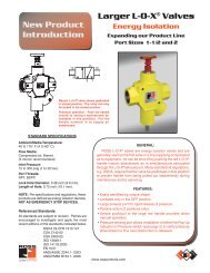
Energy Isolation for Lockout/Tagout (LOTO)<br />
L-O-X ® Function (Lockout and Exhaust)<br />
with Combination Manual/Solenoid Operation<br />
• Easily identified by red handle<br />
• Lockable only in the OFF position<br />
• Large exhaust port exceeds inlet size for rapid release of pressure<br />
• Simple push/pull of the large red handle accommodates reduced manual actuation forces, allowing easy operation<br />
• Integrated sensing port for pressure verification - see page 19 for verification accessories<br />
• Solenoid-operated models for air dump function (Category 1). For<br />
Combination Solenoid / Manual Models<br />
Category 2 versions see page 11.<br />
Lockout /<br />
Tagout<br />
See bulletin 372 for more information.<br />
PIPE SIZE<br />
2 - 1/4 NPTF<br />
3 - 3/8 NPTF<br />
4 - 1/2 NPTF<br />
C - 1/4 BSPP<br />
D - 3/8 BSPP<br />
E - 1/2 BSPP<br />
GAUGE<br />
A - No Gauge<br />
B - (0-200 psig)<br />
C - (0-60 psig)<br />
D - No Gauge with Panel Mount Nut<br />
E - (0-200 psig) Gauge with Panel Mount Nut<br />
F - (0-60 psig) Gauge with Panel Mount Nut<br />
ADJUSTMENT RANGE<br />
A - 0-150 psig (0-10 bar); reverse flow<br />
B - 0-100 psig (0-6.8 bar); standard, reverse flow<br />
C - 0-50 psig (0-3.4 bar); reverse flow<br />
Port Size<br />
Model Number* In-Out Exhaust In-Out Out-Exh.<br />
Y2773A2072** 1/4 1/2 2.5 3.1<br />
Y2773A3072** 3/8 1/2 3.6 5.3<br />
Y2773A4082** 1/2 1/2 3.3 5.3<br />
Y2773A4072** 1/2 1 6.3 9.2<br />
Y2773A5072** 3/4 1 7.7 11<br />
Y2773A6082** 1 1 8.0 12<br />
Y2773A6072** 1 11/2 23 34<br />
Y2773A7072** 11/4 11/2 30 32<br />
Y2773A8082** 11/2 11/2 30 31<br />
Y2773A8072** 11/2 21/2 68 70<br />
Y2773A8072** 2 21/2 70 70<br />
Y2773A9082** 21/2 21/2 70 71<br />
* NPT port threads. For BSPP threads, insert letter “D” after “Y”<br />
in the model number, e.g. YD2773A2072. Body paint: Yellow.<br />
** Specify voltage and hertz when ordering.<br />
C V<br />
6 © 2011 <strong>ROSS</strong> CONTROLS ® . All Rights Reserved.
Soft Start Lockout / Tagout<br />
Energy Isolation with Soft Start for LOTO<br />
Combination L-O-X ® Valve with EEZ-ON ® Function<br />
• Easily identified by blue handle<br />
• Gradual re-application of pneumatic pressure prevents rapid equipment movement at startup<br />
• Lockable only in the OFF position<br />
• Large exhaust port exceeds inlet size for rapid release of pressure<br />
• Positive action (2 positions only)<br />
• Simple push/pull of the large blue handle provides positive direct manual operation<br />
• Integrated sensing port for pressure verification - see page 19 for verification accessories<br />
Model Port Size C V<br />
Number* In-Out Exhaust In-Out Out-Exh.<br />
Y1523B3102 3/8 3/4 6.0 8.0<br />
Y1523B4102 1/2 3/4 7.1 8.3<br />
Y1523B5112 3/4 3/4 8.0 9.5<br />
Y1523B5102 3/4 11/4 12.0 10.9<br />
Y1523B6102 1 11/4 13.7 12.0<br />
Y1523B7112 11/4 11/4 16.2 12.8<br />
* NPT port threads. For BSPP threads, insert letter “D” after “Y” in<br />
the model number, e.g., YD1523B3102. Body paint: Yellow.<br />
See bulletin 372 for more information.<br />
Soft Start<br />
Lockout / Tagout<br />
Combination L-O-X ® Valve with EEZ-ON ® Function<br />
with Manual or Manual /Solenoid Operation<br />
• Easily identified by blue handle<br />
• Gradual re-application of pneumatic pressure prevents rapid equipment movement at<br />
startup<br />
• Lockable only in the OFF position<br />
• Large exhaust port exceeds inlet size for rapid release of pressure<br />
• Simple push/pull of the large blue handle provides positive direct manual operation<br />
• Integrated sensing port for pressure verification - see page 19 for verification accessories<br />
Manual<br />
Model Number*<br />
Y2783B2055<br />
Y2783B3055<br />
Y2783B4065<br />
Y2783B4055<br />
Y2783B5055<br />
Y2783B6065<br />
Y2783A6055<br />
Y2783A7055<br />
Y2783A8065<br />
Combination<br />
Solenoid / Manual<br />
Model Number*<br />
Y2773B2075**<br />
Y2773B3075**<br />
Y2773B4085**<br />
Y2773B4075**<br />
Y2773B5075**<br />
Y2773B6085**<br />
Y2773B6075**<br />
Y2773B7075**<br />
Y2773B8085**<br />
Port Size<br />
In-Out Exhaust<br />
1/4 1/2<br />
3/8 1/2<br />
1/2 1/2<br />
1/2 1<br />
3/4 1<br />
1 1<br />
1 11/2<br />
11/4 11/2<br />
11/2 11/2<br />
C V<br />
In-Out Out-Exh.<br />
2.5 3.1<br />
3.6 5.3<br />
3.3 5.3<br />
10.0 13.0<br />
12.0 15.0<br />
12.0 16.0<br />
23.0 34.0<br />
30.0 32.0<br />
30.0 31.0<br />
* NPT port threads. For BSPP threads, insert letter “D” after “Y” in the model number, e.g.,<br />
YD2773B2075. Body paint: Yellow.<br />
** Specify voltage and hertz when ordering.<br />
Soft Start<br />
Lockout / Tagout<br />
See bulletin 372 for more information.<br />
www.rosscontrols.com<br />
7
BG-PRUFZERT<br />
BG-PRUFZERT<br />
Air Dump / Release<br />
Control Reliable Energy Isolation<br />
DM 1 Series E Size 2<br />
3/2 Double Valve with Dynamic Moni<strong>to</strong>ring<br />
• Rapid response time <strong>to</strong> minimize s<strong>to</strong>pping time<br />
• Self-contained dynamic moni<strong>to</strong>ring system<br />
• Status Indica<strong>to</strong>r switch for valve condition (ready <strong>to</strong> run) feedback<br />
• Highly contaminant <strong>to</strong>lerant poppet construction<br />
• Line mounted<br />
Do not use in power press clutch/brake applications.<br />
Air Dump /<br />
Release<br />
EMIII HZ<br />
99035<br />
ISO 13849-1:2006 Category 3<br />
PL e applications<br />
(approval pending)<br />
See brochure NPS006 for more information.<br />
Model Port Size C V<br />
Number* In Out In-Out Out-Exh.<br />
DM1ENA20**31 1/4 1/2 1.34 2.43<br />
DM1ENA21**31 3/8 1/2 1.92 2.43<br />
* NPT port threads. For BSPP threads , replace “N” in the model number with a “D”.<br />
** Insert voltage code: “A” = 24 volts DC, “B” = 110 volts AC, “C” = 220 volts AC,<br />
“D” = 12 volts DC; M12 connec<strong>to</strong>rs available, consult <strong>ROSS</strong>.<br />
Wiring kits and accessories available, see pages 19 thru 23.<br />
Sistema library data available (see page 24).<br />
DM 2® Series E Size 2<br />
3/2 Double Valve with Dynamic Moni<strong>to</strong>ring and Memory<br />
• Rapid response time <strong>to</strong> minimize s<strong>to</strong>pping time<br />
• Dynamic memory of abnormal function retains lockout condition and<br />
this prevents unintentional reset with removal of air or electricity<br />
• Self-contained dynamic moni<strong>to</strong>ring system requires no additional<br />
valve moni<strong>to</strong>ring controls<br />
• Electrical reset valve<br />
• Status Indica<strong>to</strong>r switch for valve condition (ready <strong>to</strong> run) feedback<br />
• Highly contaminant <strong>to</strong>lerant poppet construction<br />
• Line mounted<br />
Do not use in power press clutch/brake applications.<br />
Air Dump /<br />
Release<br />
EMIII HZ<br />
99035<br />
ISO 13849-1:2006 Category 4<br />
PL e applications<br />
(approval pending)<br />
See brochure NPS007 for more information.<br />
Model Port Size C V<br />
Number* In Out In-Out Out-Exh.<br />
DM2ENA20**21 1/4 1/2 1.34 2.43<br />
DM2ENA21**21 3/8 1/2 1.92 2.43<br />
* NPT port threads. For BSPP threads , replace “N” in the model number with a “D”.<br />
** Insert voltage code: “A” = 24 volts DC, “B” = 110 volts AC, “C” = 220 volts AC,<br />
“D” = 12 volts DC; M12 connec<strong>to</strong>rs available, consult <strong>ROSS</strong>.<br />
Wiring kits and accessories available, see pages 19 thru 23.<br />
Sistema library data available (see page 24).<br />
8 © 2011 <strong>ROSS</strong> CONTROLS ® . All Rights Reserved.
Electrical / <strong>Pneumatic</strong> Energy Isolation (LOTO)<br />
Air Entry Package with Control Reliable Energy Isolation<br />
Category 3 with Modular L-O-X ® and DM 1 Series E<br />
• Pre-engineered panel-mounted design with air entry with:<br />
filter and regula<strong>to</strong>r “FR”, or<br />
filter, regula<strong>to</strong>r and lubrica<strong>to</strong>r “FRL”<br />
• Includes DM 1 Series E Double Valve with Moni<strong>to</strong>ring<br />
Do not use in power press clutch/brake applications.<br />
Pressure Switch<br />
not shown<br />
Model Air Entry Port Size C V<br />
Dimensions (inches/mm)<br />
Number* Type In Out In-Out Out-Exh. Length Width Depth<br />
RC304-09 FR 1/4 1/2 1.3 2.4 13.00 (330.0) 11.00 (279.0) 5.40 (134.7)<br />
RC306-09 FR 3/8 1/2 1.9 2.4 13.00 (330.0) 11.00 (279.0) 5.40 (134.7)<br />
RC304L-09 FRL 1/4 1/2 1.3 2.4 13.00 (330.0) 11.00 (279.0) 5.40 (134.7)<br />
RC306L-09 FRL 3/8 1/2 1.9 2.4 13.00 (330.0) 11.00 (279.0) 5.40 (134.7)<br />
Electrical /<br />
<strong>Pneumatic</strong> Energy<br />
Isolation (LOTO)<br />
* NPT port threads. Specify voltage and hertz when ordering, M12 connec<strong>to</strong>rs available, consult <strong>ROSS</strong>.<br />
Wiring kits and accessories available, see pages 19 thru 23.<br />
See brochure NPS015 for more information.<br />
Category 4 with Modular L-O-X ® and DM 2® Series E<br />
• Pre-engineered panel-mounted design with air entry with:<br />
filter and regula<strong>to</strong>r “FR”, or<br />
filter, regula<strong>to</strong>r and lubrica<strong>to</strong>r “FRL”<br />
• Includes DM 2® Series E Double Valve with Moni<strong>to</strong>ring & Memory<br />
Do not use in power press clutch/brake applications.<br />
Model Air Entry Port Size C V<br />
Dimensions (inches/mm)<br />
Number* Type In Out In-Out Out-Exh. Length Width Depth<br />
RC404-09 FR 1/4 1/2 1.3 2.4 13.00 (330.0) 11.68 (296.7) 5.40 (134.7)<br />
RC406-09 FR 3/8 1/2 1.9 2.4 13.00 (330.0) 11.68 (296.7) 5.40 (134.7)<br />
RC404L-09 FRL 1/4 1/2 1.3 2.4 13.00 (330.0) 11.68 (296.7) 5.40 (134.7)<br />
RC406L-09 FRL 3/8 1/2 1.9 2.4 13.00 (330.0) 11.68 (296.7) 5.40 (134.7)<br />
Electrical /<br />
<strong>Pneumatic</strong> Energy<br />
Isolation (LOTO)<br />
* NPT port threads. Specify voltage and hertz when ordering, M12 connec<strong>to</strong>rs available, consult <strong>ROSS</strong>.<br />
Wiring kits and accessories available, see pages 19 thru 23.<br />
See brochure NPS015 for more information.<br />
www.rosscontrols.com<br />
9
BG-PRUFZERT<br />
Air Dump / Release<br />
Electrical / <strong>Pneumatic</strong> Energy Isolation (LOTO)<br />
Control Reliable Energy Isolation<br />
DM 2® Series C Sizes 4, 8, 12, 30<br />
3/2 Double Valve with Dynamic Moni<strong>to</strong>ring and Memory<br />
• Rapid response time <strong>to</strong> minimize s<strong>to</strong>pping time<br />
• Dynamic memory of abnormal function retains lockout condition and this prevents<br />
unintentional reset with removal of air or electricity<br />
• Electrical reset valve<br />
• Status Indica<strong>to</strong>r switch for valve condition (ready <strong>to</strong> run) feedback<br />
• Self-contained dynamic moni<strong>to</strong>ring system requires no additional valve moni<strong>to</strong>ring controls<br />
• Highly contaminant <strong>to</strong>lerant poppet construction<br />
• Base mounted<br />
Do not use in power press clutch/brake applications.<br />
Air Dump /<br />
Release<br />
EMIII HZ<br />
99035<br />
ISO 13849-1:2006 Category 4<br />
PL e applications<br />
See brochure NPS010 for more information.<br />
Model Port Size C V<br />
Number* In Out In-Out Out-Exh.<br />
DM2CNA42**21 1/2 1/2 3 10<br />
DM2CNA54**21 3/4 3/4 4.4 13<br />
DM2CNA55**21 1 1 4.4 13<br />
DM2CNA66**21 1 1 8.5 20<br />
DM2CNA88**21 11/2 2 22 64<br />
* NPT port threads. For BSPP threads , replace “N” in the model number with a “D”.<br />
** Insert voltage code: “A” = 24 volts DC, “B” = 110 volts AC;<br />
M12 connec<strong>to</strong>rs available, consult <strong>ROSS</strong>.<br />
Wiring kits and accessories available, see pages 19 thru 23.<br />
Sistema library data available (see page 24).<br />
Air Entry Package with Control Reliable Energy Isolation<br />
Category 4 with Manual L-O-X ® and DM 2® Series C<br />
• Pre-engineered panel-mounted design with air entry with a filter<br />
and regula<strong>to</strong>r “FR”, or filter, regula<strong>to</strong>r and lubrica<strong>to</strong>r “FRL”<br />
• Includes DM 2® Series C Double Valve with Moni<strong>to</strong>ring & Memory<br />
Do not use in power press clutch/brake applications.<br />
Model Air Entry Port Size C V<br />
Dimensions (inches/mm)<br />
Number* Type In Out In-Out Out-Exh. Length Width Depth<br />
RC408-06 FR 1/2 1/2 3 10 24.0 (610) 14.5 (369) 7.4 (187)<br />
RC412-06 FR 3/4 3/4 4.4 13 24.0 (610) 15.7 (399) 8.3 (211)<br />
RC416-06 FR 1 1 4.4 13 27.0 (686) 19.0 (483) 9.0 (229)<br />
Electrical /<br />
<strong>Pneumatic</strong> Energy<br />
Isolation (LOTO)<br />
RC408L-06 FRL 1/2 1/2 3 10 24.0 (610) 14.5 (369) 7.4 (187)<br />
RC412L-06 FRL 3/4 3/4 4.4 13 24.0 (610) 15.7 (399) 8.3 (211)<br />
RC416L-06 FRL 1 1 4.4 13 31.0 (788) 19.0 (483) 9.0 (229)<br />
* NPT port threads. Specify voltage and hertz when ordering, M12 connec<strong>to</strong>rs available,<br />
consult <strong>ROSS</strong>.<br />
Wiring kits and accessories available, see pages 19 thru 23.<br />
10 © 2011 <strong>ROSS</strong> CONTROLS ® . All Rights Reserved.
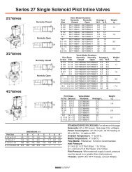
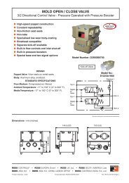
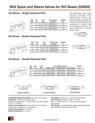
3/2 Normally Closed Sensing Valve<br />
Air Dump / Release<br />
• Senses internal position & state<br />
• Electrical feedback via DPST switch ( Double-Pole Single-Throw)<br />
• Directly operated safety-rated force-guided positive-break status switch (DPST)<br />
• Poppet construction for near zero leakage & dirt <strong>to</strong>lerance<br />
***EN 954-1, ISO 13849-1,<br />
& AS4024-1<br />
Air Dump /<br />
Release<br />
Solenoid Pilot Controlled Pressure Controlled Port Size C V<br />
Model Number* Model Number* In–Out Exhaust In-Out Out-Exh.<br />
SV27NC305407PSAA1A** SV27NC305405ASAA 1/2 *** 1 6.3 9.2<br />
SV27NC305507PSAA1A** SV27NC305505ASAA 3/4 *** 1 7.7 11<br />
SV27NC305607PSAA1A** SV27NC305605ASAA 1 *** 1 8.0 12<br />
SV27NC307607PSAA1A** SV27NC307605ASAA 1*** 11/2 23 34<br />
SV27NC307707PSAA1A** SV27NC307705ASAA 11/4*** 11/2 30 32<br />
SV27NC307807PSAA1A** SV27NC307805ASAA 11/2*** 11/2 30 32<br />
SV27NC309807PSAA1A** SV27NC309805ASAA 11/2 21/2 68 70<br />
SV27NC309907PSAA1A** SV27NC309905ASAA 2 21/2 70 70<br />
SV27NC309957PSAA1A** SV27NC309955ASAA 21/2 21/2 70 71<br />
* NPT port threads. For BSPP threads, replace “N” in the model number with a “D”.<br />
** “1A”=120 volts 60 Hz solenoids. For 240 volts 60 Hz, change “1A” <strong>to</strong> “2A”; for 24 volts 60 Hz <strong>to</strong> “3A”;<br />
for 24 volts DC <strong>to</strong> “1D”.<br />
Wiring kits and accessories available, see pages 19 thru 23.<br />
See brochure NPS279 for more information.<br />
3/2 Normally Closed Sensing Valve with L-O-X ®<br />
• Senses internal position & state<br />
• Electrical feedback via DPST switch ( Double-Pole Single-Throw)<br />
• Directly operated safety-rated force-guided positive-break status switch (DPST)<br />
• Poppet construction for near zero leakage & dirt <strong>to</strong>lerance<br />
Solenoid Pilot Controlled Pressure Controlled Port Size C V<br />
Model Number* Model Number* In–Out Exhaust In-Out Out-Exh.<br />
SV27NC3L5407PSAA1A** SV27NC3L5405ASAA 1/2 1 6.3 9.2<br />
SV27NC3L5507PSAA1A** SV27NC3L5505ASAA 3/4 1 7.7 11<br />
SV27NC3L5607PSAA1A** SV27NC3L5605ASAA 1 1 8.0 12<br />
SV27NC3L7607PSAA1A** SV27NC3L7605ASAA 1 11/2 23 34<br />
SV27NC3L7707PSAA1A** SV27NC3L7705ASAA 11/4 11/2 30 32<br />
SV27NC3L7807PSAA1A** SV27NC3L7805ASAA 11/2 11/2 30 32<br />
* NPT port threads. For BSPP threads, replace “N” in the model number with a “D”.<br />
** “1A”=120 volts 60 Hz solenoids. For 240 volts 60 Hz, change “1A” <strong>to</strong> “2A”; for 24 volts 60 Hz <strong>to</strong> “3A”;<br />
for 24 volts DC <strong>to</strong> “1D”.<br />
Wiring kits and accessories available, see pages 19 thru 23.<br />
Air Dump /<br />
Release<br />
www.rosscontrols.com<br />
11
Electrical / <strong>Pneumatic</strong> Energy Isolation (LOTO)<br />
Air Entry Package with 3/2 Normally Closed<br />
Sensing Valve<br />
Category 2 with Manual L-O-X ® and SV27 Sensing Valve<br />
• Pre-engineered panel-mounted design with air entry with filter<br />
and regula<strong>to</strong>r “FR”, or filter, regula<strong>to</strong>r, and lubrica<strong>to</strong>r “FRL”<br />
• Includes 3/2 Normally Closed Sensing Valve<br />
Electrical /<br />
<strong>Pneumatic</strong> Energy<br />
Isolation (LOTO)<br />
Model Air Entry Port Size C V<br />
Dimensions (inches/mm)<br />
Number* Type In Out In-Out Out-Exh. A B C<br />
RC208-06 FR 1/2 1/2 6.3 9.2 23.0 (585) 12.8 (326) 6.7 (171)<br />
RC212-06 FR 3/4 3/4 7.7 11 23.0 (585) 12.8 (326) 6.7 (171)<br />
RC216-06 FR 1 1 8.0 12 28.0 (712) 17.0 (432) 9.5 (242)<br />
RC208L-06 FRL 1/2 1/2 6.3 9.2 23.0 (585) 12.8 (326) 6.7 (171)<br />
RC212L-06 FRL 3/4 3/4 7.7 11 23.0 (585) 12.8 (326) 6.7 (171)<br />
RC216L-06 FRL 1 1 8.0 12 31.8 (808) 17.0 (432) 9.5 (242)<br />
* NPT port threads. Specify voltage and hertz when ordering, M12 connec<strong>to</strong>rs available, consult <strong>ROSS</strong>.<br />
Wiring kits and accessories available, see pages 19 thru 23.<br />
Category 2 with Modular L-O-X ® and SV27 Sensing Valve<br />
• Pre-engineered panel-mounted design with air entry with filter<br />
and regula<strong>to</strong>r “FR”, or filter, regula<strong>to</strong>r, and lubrica<strong>to</strong>r “FRL”<br />
• Includes 3/2 Normally Closed Sensing Valve<br />
Electrical /<br />
<strong>Pneumatic</strong> Energy<br />
Isolation (LOTO)<br />
See brochure NPS015 for more information.<br />
Model Air Entry Port Size C V<br />
Dimensions (inches/mm)<br />
Number* Type In Out In-Out Out-Exh. A B C<br />
RC208-09 FR 1/2 1/2 6.3 9.2 14.80 (374.9) 11.00 (279.0) 6.60 (167.7)<br />
RC208L-09 FRL 1/2 1/2 6.3 9.2 14.80 (374.9) 11.00 (279.0) 6.60 (167.7)<br />
* NPT port threads. Specify voltage and hertz when ordering, M12 connec<strong>to</strong>rs available, consult <strong>ROSS</strong>.<br />
Wiring kits and accessories available, see pages 19 thru 23.<br />
12 © 2011 <strong>ROSS</strong> CONTROLS ® . All Rights Reserved.
BG-PRUFZERT<br />
BG-PRUFZERT<br />
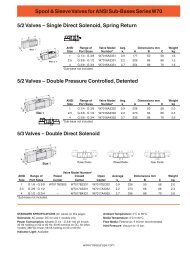
Cylinder Return <strong>to</strong> Home Position<br />
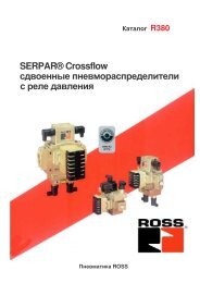
Control Reliable 5/2 Double Valve - Series 77 C<strong>ROSS</strong>MIRROR ®<br />
Solenoid Pilot Controlled<br />
• Self-contained dynamic moni<strong>to</strong>ring system requires no additional valve moni<strong>to</strong>ring controls<br />
• Base mounted, stainless steel spool valve construction<br />
• Status indication switch (ready-<strong>to</strong>-run) <strong>to</strong> inform machine controller of valve condition;<br />
MUST be integrated in<strong>to</strong> machine controls in order <strong>to</strong> prevent run signal until fault is cleared in valve<br />
• Applications include small size pneumatic cylinder-operated presses, valve opera<strong>to</strong>rs, and safety latches<br />
• Base mounted, stainless steel spool valve construction<br />
Do not use in power press clutch/brake applications.<br />
Size 2<br />
Model Port Size C V<br />
Pressure Replacements*<br />
Number• 1 2, 3, 4, 5 1-2 1-4 2-3 4-5 Switch Valve No. Base No.<br />
7776A3410 1/2 3/8 2.0 1.6 1.6 2.8 Without 7776A3400 996C91<br />
7776A3411 1/2 3/8 2.0 1.6 1.6 2.8 With 7776A3401 996C91<br />
Size 4<br />
7776A4420 3/4 1/2 3.2 3.4 2.7 7.2 Without 7776A4400 1049C91<br />
7776A4421 3/4 1/2 3.2 3.4 2.7 7.2 With 7776A4401 1049C91<br />
7776A5410 3/4 3/4 3.2 3.4 2.7 7.2 Without 7776A4400 1153C91<br />
7776A5411 3/4 3/4 3.2 3.4 2.7 7.2 With 7776A4401 1153C91<br />
* Model number includes base supplied with NPT threads. For G threads, order model or base with a<br />
“D” prefix, e.g., D7776A3410, D996C91.<br />
For pressure switch option, order model or valve with a “Z”suffix for 110 AC or “W” suffix for<br />
24 volts DC, e.g., 7776A3411Z, 7776A3401W.<br />
Sistema library data available (see page 24).<br />
Cylinder<br />
Return <strong>to</strong> Home<br />
Position<br />
EMIII HZ<br />
99035<br />
ISO 13849-1:2006 Category 4<br />
PL e applications<br />
See bulletin E383 for more information.<br />
Two-Hand Pressure Controlled<br />
• Requires two inputs within 500 ms<br />
• Self-contained dynamic moni<strong>to</strong>ring system requires no additional valve moni<strong>to</strong>ring controls<br />
• Senses asynchronous inputs via status indica<strong>to</strong>r switch<br />
• Status indication switch available <strong>to</strong> be integrated with electrical safety control system where available<br />
• Applications include small size pneumatic cylinder-operated presses, valve opera<strong>to</strong>rs, and safety latches<br />
• Base mounted, stainless steel spool valve construction<br />
Do not use in power press clutch/brake applications.<br />
Cylinder<br />
Return <strong>to</strong> Home<br />
Size 2<br />
Position<br />
Model Port Size C V<br />
Pressure Replacements*<br />
Number* 1 2, 3, 4, 5 1-2 1-4 2-3 4-5 Switch Valve No. Base No.<br />
7786A3410 1/2 3/8 2.0 1.6 1.6 2.8 Without 7786A3400 996C91<br />
7786A3411 1/2 3/8 2.0 1.6 1.6 2.8 With 7786A3401 996C91<br />
Size 4<br />
7786A4420 3/4 1/2 3.2 3.4 2.7 7.2 Without 7786A4400 1049C91<br />
7786A4421 3/4 1/2 3.2 3.4 2.7 7.2 With 7786A4401 1049C91<br />
7786A5410 3/4 3/4 3.2 3.4 2.7 7.2 Without 7786A4400 1153C91<br />
7786A5411 3/4 3/4 3.2 3.4 2.7 7.2 With 7786A4401 1153C91<br />
* Model number includes base supplied with NPT threads. For G threads, order model or base with a<br />
“D” prefix, e.g., D7786A3410, D996C91.<br />
For pressure switch option, order model or valve with a “Z” suffix for 110 AC or “W” suffix for<br />
24 volts DC, e.g., 7786A3411Z, 7786A3401Z.<br />
Sistema library data available (see page 24).<br />
EMIII HZ<br />
99035<br />
ISO 13849-1:2006 Category 4<br />
PL e applications<br />
See brochure NP005 for more information.<br />
www.rosscontrols.com<br />
13
Load Holding<br />
2/2 PO Check with Sensing<br />
Pressure Controlled or Solenoid Pilot Controlled<br />
• Poppet construction for near zero leakage & dirt <strong>to</strong>lerance<br />
• Directly operated safety-rated force-guided positive-break<br />
status switch (DPST)<br />
• Holds a vertical load in the event of loss of air pressure<br />
(and loss of electrical power with solenoid operated)<br />
EN 954-1, ISO 13849-1,<br />
& AS4024-1<br />
See bulletin 430 for more information.<br />
Load<br />
Holding<br />
Solenoid Pilot Controlled<br />
Model Number*<br />
SV27NC115408CSAA1A**<br />
SV27NC115508CSAA1A**<br />
SV27NC115608CSAA1A**<br />
SV27NC117608CSAA1A**<br />
SV27NC117708CSAA1A**<br />
SV27NC117808CSAA1A**<br />
Pressure Controlled<br />
Model Number*<br />
SV27NC115405ASAA<br />
SV27NC115505ASAA<br />
SV27NC115605ASAA<br />
SV27NC117605ASAA<br />
SV27NC117705ASAA<br />
SV27NC117805ASAA<br />
Port<br />
Size<br />
1/2<br />
3/4<br />
1<br />
1<br />
11/4<br />
11/2<br />
C V<br />
In-Out<br />
4.5<br />
8.3<br />
10.3<br />
20.2<br />
29.1<br />
31.4<br />
* NPT port threads. For BSPP threads, replace “N” in the model number with a “D”.<br />
** “1A”=120 volts 60 Hz solenoids. For 24 volts DC change “1A” <strong>to</strong> “1D”.<br />
Wiring kits and accessories available, see pages 19 thru 23.<br />
Redundant 2/2 PO Check with Sensing<br />
Pressure Controlled or Solenoid Pilot Controlled<br />
• Poppet construction for near zero leakage & dirt <strong>to</strong>lerance<br />
• Directly operated safety-rated force-guided positive-break status<br />
switch (DPST)<br />
• Holds a vertical load in the event of loss of air pressure<br />
(and electrical power with solenoid operated models)<br />
Solenoid Pilot Controlled<br />
Model Number*<br />
Pressure Controlled<br />
Model Number*<br />
Port<br />
Size<br />
C V<br />
In-Out<br />
Load<br />
Holding<br />
SV27NC555408CSAA1A**<br />
SV27NC555508CSAA1A**<br />
SV27NC555608CSAA1A**<br />
SV27NC557608CSAA1A**<br />
SV27NC557708CSAA1A**<br />
SV27NC557808CSAA1A**<br />
SV27NC555405ASAA<br />
SV27NC555505ASAA<br />
SV27NC555605ASAA<br />
SV27NC555405ASAA<br />
SV27NC555505ASAA<br />
SV27NC555605ASAA<br />
1/2<br />
3/4<br />
1<br />
1<br />
11/4<br />
11/2<br />
4.5<br />
8.3<br />
10.3<br />
12.1<br />
18.7<br />
22.3<br />
EN 954-1, ISO 13849-1,<br />
& AS4024-1<br />
* NPT port threads. For BSPP threads, replace “N” in the model number with a “D”.<br />
** “1A”=120 volts 60 Hz solenoids. For 24 volts DC change “1A” <strong>to</strong> “1D”.<br />
Wiring kits and accessories available, see pages 19 thru 23.<br />
See bulletin 430 for more information.<br />
14 © 2011 <strong>ROSS</strong> CONTROLS ® . All Rights Reserved.
Right-Angle PO Check Valves<br />
Cylinder Position Holding<br />
Models with Threaded Banjo and Push-<strong>to</strong>-Connect Fitting<br />
• Right angle design with banjo for easy positioning of pipe or tubing<br />
• Threaded outlet ports available with NPT or G threads<br />
• Inlet ports available with NPTF threaded or push-<strong>to</strong>-connect fittings<br />
• Quick and easy installation<br />
• Galvanized zinc plated brass body construction<br />
• Lube or non-lube operation<br />
Cylinder Position<br />
Holding<br />
Models with Threaded Banjo<br />
Signal<br />
Tightening<br />
Port Port Size Valve Model Avg. C V<br />
Torque Max.<br />
Thread Port 1* Port 2** Number 1 <strong>to</strong> 2 2 <strong>to</strong> 1 Ft-lb (Nm)<br />
10-32 UNF 1/8 1/8 1958A1010 0.4 0.4 22.13 (30)<br />
10-32 UNF 1/4 1/4 1958A2010 0.8 0.7 14.75 (20)<br />
10-32 UNF 3/8 3/8 1958A3010 1.2 1.3 22.13 (30)<br />
10-32 UNF 1/2 1/2 1958A4010 2.3 2.2 29.50 (40)<br />
M5 G1/8 G1/4 D1958A1010 0.4 0.4 7.38 (10)<br />
M5 G1/4 G1/4 D1958A2010 0.8 0.7 8.85 (12)<br />
M5 G3/8 G3/8 D1958A3010 1.2 1.3 14.75 (20)<br />
M5 G1/2 G1/2 D1958A4010 2.3 2.2 22.13 (30)<br />
* Threads in port 1 are female.<br />
** Port 2 threads are male.<br />
Models with Push-<strong>to</strong>-Connect Fitting<br />
Signal Port Size<br />
Port Port 1 # Port 2** Valve Model Avg. C V<br />
Tightening<br />
Torque Max.<br />
Thread (tube size) (thread size) Number 1 <strong>to</strong> 2 2 <strong>to</strong> 1 Ft-lb (Nm)<br />
10-32 UNF 5/32” 1/8 1958A1115 0.4 0.4 11.06 (15)<br />
10-32 UNF 1/4” 1/8 1958A1120 0.4 0.4 11.06 (15)<br />
10-32 UNF 1/4” 1/4 1958A2120 0.8 0.7 14.75 (20)<br />
10-32 UNF 3/8” 1/4 1958A2130 0.8 0.7 14.75 (20)<br />
10-32 UNF 3/8” 3/8 1958A3130 1.2 1.3 22.13 (30)<br />
M5 4 mm G1/8 D1958A1140 0.4 0.4 7.38 (10)<br />
M5 6 mm G1/8 D1958A1160 0.4 0.4 7.38 (10)<br />
M5 8 mm G1/8 D1958A1180 0.4 0.4 7.38 (10)<br />
M5 6 mm G1/4 D1958A2160 0.8 0.7 8.85 (12)<br />
M5 8 mm G1/4 D1958A2180 0.8 0.7 8.85 (12)<br />
M5 10 mm G1/4 D1958A2110 0.8 0.7 8.85 (12)<br />
M5 8 mm G3/8 D1958A3180 1.2 1.3 14.75 (20)<br />
M5 10 mm G3/8 D1958A3110 1.2 1.3 14.75 (20)<br />
# Port 1 tubing size in inches (”) or millimeters (mm).<br />
** Port 2 threads are male.<br />
Manual Overrides<br />
Model Number Port Size Description<br />
for Models with Threaded Banjo<br />
1998A1010 10-32 10-32 Manual Operated Check<br />
for Models with Push-<strong>to</strong>-Connect Fitting<br />
1998A1020 1/4 10-32 Manual Operated Check<br />
1998A1015 5/32 10-32 Manual Operated Check<br />
Pilot Signal<br />
Port<br />
Pilot Signal<br />
Port<br />
Port 1<br />
Threaded Banjo<br />
Port 1<br />
Port 2<br />
Port 2<br />
Push-<strong>to</strong>-Connect Fitting<br />
www.rosscontrols.com<br />
15
Load Holding<br />
Cylinder Position Holding<br />
PO Check Valves (Non-Critical)<br />
For Cylinder Position Holding And Load Holding<br />
with Trapped Pressure Release<br />
• Available with au<strong>to</strong>matic or manual trapped pressure release<br />
when pressure is removed from the Blowdown Signal Port (BP)<br />
• Poppet construction for near zero leakage<br />
• Applications include Air Holding and Cylinder Load Holding<br />
Load<br />
Holding<br />
Cylinder Position<br />
Holding<br />
Type A Single<br />
PO Check Valve<br />
Type A Single<br />
PO Check Valve<br />
(Remote Trapped<br />
Pressure Relief)<br />
Type A Single<br />
PO Check Valve<br />
(Manual Trapped<br />
Pressure Relief)<br />
Type B Single<br />
PO Check Valve<br />
Type C Dual<br />
PO Check Valve<br />
Type D Internal Pilot Dual<br />
PO Check Valve<br />
(Remote Trapped<br />
Pressure Relief)<br />
Type D Internal Pilot Dual<br />
PO Check Valve<br />
(Manual Trapped<br />
Pressure Relief)<br />
Pressure Controlled<br />
Valve Port PO Check Avg.<br />
Type** Size Model Number C V<br />
1/4 2751A2908 2.2<br />
A 3/8 2751A3908 2.9<br />
Single 1/2 2751A4915 3.2<br />
3/8 2751B3922 2.6<br />
A<br />
1/2 2751B4922 2.8<br />
Remote<br />
3/4 2751B5917 9.2<br />
3/8 2751A3920 2.6<br />
A<br />
1/2 2751A4920 2.8<br />
Manual<br />
3/4 2751A5919 9.2<br />
1/4 2751A2903 2.3<br />
3/8 2751A3901 3.8<br />
1/2 2751A4902 4.0<br />
1/2 2751A4905 7.7<br />
B 3/4 2751A5903 9.0<br />
Single 1 2751A6901 9.0<br />
1 2751B6490 24<br />
11/4 2751B7901 29<br />
11/2 2751B8920 29<br />
3/8 2768C3900 2.9<br />
C 1/2 2768C4900 3.2<br />
Dual 3/4 2798C5900 8.5*<br />
1 2798A6900 8.5*<br />
3/8 2768D3901 2.9<br />
D 1/2 2768D4901 3.2<br />
Remote 3/4 2768D5901 8.5*<br />
1 2768A6901 8.5*<br />
3/8 2768D3904 2.9<br />
D 1/2 2768D4904 3.2<br />
Manual 3/4 2768D5904 8.5*<br />
1 2768D6904 8.5*<br />
*Effective C V<br />
varies with load and pressure drop.<br />
Consult <strong>ROSS</strong> for specifics on your system.<br />
** NPT port threads. For BSPP threads, add a “D”<br />
prefix <strong>to</strong> the model number.<br />
Type E Solenoid Pilot<br />
Dual PO Check Valve<br />
See bulletin 430 for more information.<br />
Solenoid Pilot Controlled<br />
24 volts DC 24 volts DC<br />
Valve Port DIN 3-Pin Mini 3-Pin Mini 4-Pin Micro Avg.<br />
Type** Size Connec<strong>to</strong>r Connec<strong>to</strong>r Connec<strong>to</strong>r Connec<strong>to</strong>r C V<br />
3/8 2778D3900 2778D3901 2778D3902 2778D3904 2.9<br />
E<br />
1/2 2778D4900 2778D4901 2778D4902 2778D4904 3.2<br />
3/4 2778D5900 2778D5901 2778D5902 2778D5904 8.5*<br />
1 2778B6900 2778B6901 2778B6902 2778B6904 8.5*<br />
*Effective C V<br />
varies with load and pressure drop. Consult <strong>ROSS</strong> for specifics on your system.<br />
** NPT port threads. For BSPP threads, add a “D” prefix <strong>to</strong> the model number.<br />
16 © 2011 <strong>ROSS</strong> CONTROLS ® . All Rights Reserved.
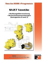
Load Holding<br />
Cylinder Position Holding<br />
CIRCUIT FEATURES:<br />
• Trapped pressure between check valve and cylinder is exhausted<br />
when the air supply at the Blowdown Signal Port (BP) is lost or<br />
locked-out<br />
• Cylinder moves as long as the control valve solenoid is energized;<br />
use for continuous motion or jogging<br />
• Cylinder remains stationary if neither control valve solenoid is<br />
energized, or if electrical signal is lost<br />
Single Pilot Operated Check Valve<br />
with Trapped Pressure Relief Application<br />
L-O-X (Lockout<br />
& Exhaust Valve)<br />
3<br />
1<br />
12<br />
2<br />
10<br />
14<br />
5 4<br />
1<br />
3<br />
2<br />
12<br />
3-Position, Open-<br />
Center Control Valve<br />
Single PO Check Valve<br />
Vertical<br />
Cylinder<br />
Dual Pilot Operated Check Valve<br />
Manual Trapped Pressure Relief Application<br />
Dual Pilot Operated Check Valve<br />
Remote Trapped Pressure Relief Application<br />
Cylinder<br />
Cylinder<br />
Flow<br />
Control<br />
Valves<br />
Remote-controlled<br />
Check Valve Relief<br />
Flow<br />
Control<br />
Valves<br />
Remote-controlled<br />
Check Valve Relief<br />
A<br />
B<br />
Dual Check<br />
Valve with<br />
Internal Pilot<br />
Dual Check<br />
Valve with<br />
Internal Pilot<br />
C1<br />
C2<br />
C1<br />
C2<br />
V1<br />
3- Position, Open-<br />
Center Control Valve<br />
V2<br />
L-O-X Valve<br />
Trapped pressure<br />
between check<br />
valve and cylinder<br />
is exhausted when<br />
push but<strong>to</strong>ns A and<br />
B are pressed.<br />
V1<br />
3- Position, Open-<br />
Center Control Valve<br />
V2<br />
P<br />
Holding<br />
Pressure<br />
L-O-X Valve<br />
Trapped pressure<br />
between check<br />
valve and cylinder is<br />
exhausted when the<br />
air supply at “P” port<br />
is lost or locked-out.<br />
Dual Pilot Operated Check Valve<br />
Solenoid Pilot Controlled Application<br />
CIRCUIT FEATURES:<br />
• To operate cylinder, simultaneously energize solenoids A and<br />
C or B and C<br />
• Pilot supply and exhaust are independent of control valve<br />
• Response time is not affected by exhaust restrictions of the<br />
control valve<br />
• Cylinder remains stationary if neither control valve solenoid is<br />
energized, or if electrical signal is lost<br />
• Pressure in cylinder is exhausted when the air supply at “P”<br />
port is lost or locked-out<br />
• L-O-X ® valve provides lockable shut-off of air supply, and<br />
exhausting of trapped downstream air<br />
C1<br />
Sol A<br />
Cylinder<br />
Flow<br />
Control<br />
Valves<br />
V1<br />
Sol C<br />
3- Position, Open-<br />
Center Control Valve<br />
V2<br />
Sol B<br />
Remote-controlled<br />
Check Valve Relief<br />
C2<br />
P<br />
Dual Check<br />
Valve with<br />
Solenoid Pilot<br />
and Relief<br />
Function t<br />
Holding<br />
Pressure<br />
L-O-X Valve<br />
Pressure in cylinder<br />
is exhausted when<br />
the air supply at<br />
port “P” is lost or<br />
locked-out.<br />
IMPORTANT NOTES and CAUTIONS:<br />
• Cylinder movement may occur when inlet pressure is lost. <strong>The</strong><br />
cylinder’s movement is slowed only by the restrictions of the flow<br />
control valves, and by the exhaust capacity of the check valve<br />
relief flow capacity<br />
• For best response, flow control valves should be installed between<br />
the check valve and the cylinder<br />
• Pressurizing the system after supply air has been off may cause<br />
rapid movement of the cylinder because cylinder air was exhausted<br />
while the supply air was off<br />
www.rosscontrols.com<br />
17
Soft Start<br />
EEZ-ON ® Valves - Line Mounted<br />
3-Way Normally Closed EEZ-ON ®<br />
• Gradual re-application of pneumatic pressure prevents rapid equipment<br />
movement at startup<br />
• Large exhaust port exceeds inlet size for rapid release of pressure<br />
• Pressure sensing port allows installation of either the Pop-Up Indica<strong>to</strong>r or<br />
Pressure Switch option <strong>to</strong> verify pressure is released<br />
See page 19 for accessories.<br />
Internal Pressure<br />
Controlled<br />
Model Number*<br />
2783B2037<br />
2783B3037<br />
2783B4047<br />
2783B4037<br />
2783B5037<br />
2783B6047<br />
Solenoid Pilot<br />
Controlled<br />
Model Number*<br />
2773B2037**<br />
2773B3037**<br />
2773B4047**<br />
2773B4037**<br />
2773B5037**<br />
2773B6047**<br />
Port Size<br />
In-Out Exhaust<br />
1/4 1/2<br />
3/8 1/2<br />
1/2 1/2<br />
1/2 1<br />
3/4 1<br />
1 1<br />
C V<br />
In-Out Out-Exh.<br />
2.5 3.1<br />
3.6 5.3<br />
3.3 5.3<br />
6.3 9.2<br />
7.7 11<br />
8.0 12<br />
* NPT port threads. For BSPP threads, add a “D” prefix <strong>to</strong> the model number, e.g., D2773B2037.<br />
** Specify voltage and hertz when ordering.<br />
See bulletin 372 for more information.<br />
Soft Start<br />
EEZ-ON ® Valves – Port Mounted<br />
Right Angle Style 2-Way Normally Closed EEZ-ON ®<br />
• Gradual re-application of pneumatic pressure prevents rapid equipment movement at startup<br />
• Right angle style mounts directly in cylinder ports<br />
• Available with threaded ports or push-in-tubing ports<br />
Soft Start<br />
Models with Threaded Banjo<br />
Model Port 1 Port 2 C V<br />
Number (female) (male) In-Out<br />
1969A1010* 1/8 1/8 0.7<br />
1969A2010* 1/4 1/4 1.1<br />
1969A3010* 3/8 3/8 1.9<br />
1969A4010* 1/2 1/2 2.2<br />
D1969A1010** 1/8 1/8 0.7<br />
D1969A2010** 1/4 1/4 1.1<br />
* NPT port threads.<br />
**BSPP port threads.<br />
18 © 2011 <strong>ROSS</strong> CONTROLS ® . All Rights Reserved.
HOZE-FUZE ®<br />
Protection from Broken Hose or Plastic Tubing<br />
Minimize Hose Whip<br />
Pressure Release Verification<br />
• Au<strong>to</strong>matically reduces flow <strong>to</strong> minimize hose whip<br />
upon sensing a broken hose/tube<br />
• Simple installation<br />
• Reset by shutting off air supply<br />
• For use with only non-corosive, non-flamable,<br />
non-hazardous gases<br />
Model Number*<br />
Port Size**<br />
1969A2001<br />
1/4 Male-Female<br />
1969B3001<br />
3/8 Male-Female<br />
1969A4001<br />
1/2 Male-Female<br />
1969A5002<br />
3/4 Female-Female<br />
1969A6002<br />
1 Female-Female<br />
1969B2002 1/4 Female - 1/4 Tube*<br />
* NPT port threads. For BSPP threads, add a “D” prefix <strong>to</strong> the<br />
model number, e.g., D1969A2001.<br />
** HOZE-FUZE ® size should match actual hose inside-diameter size.<br />
Minimize Hose<br />
Whip<br />
Approximate Flow Before Shut-Off in CFM (Liters/Min.)<br />
Inlet Pressure<br />
Pipe 50 psi 75 psi 100 psi 125 psi 150 psi 180 psi<br />
Size (3.4 Bar) (5.1 Bar) (6.9 Bar) (8.6 Bar) (10.3 Bar) (12.4 Bar)<br />
1/4 13 (368) 15 (424) 18 (509) 21 (594) 23 (6510 26 (736)<br />
3/8 39 (1,104) 49 (1,387) 58 (1,642) 67 (1,897) 76 (2,152) 87 (2,463)<br />
1/2 65 (1,840) 80 (2,265) 96 (2,718) 111 (3,143) 126 (3,568) 144 (4,077)<br />
3/4 110 (3,114) 126 (3,567) 142 (4,020) 158 (4,474) 174 (4,927) 193 (5.465)<br />
1 173 (4,898) 210 (5,946) 248 (7,022) 285 (8,070) 322 (9,118) 367 (10,392)<br />
Energy Release Verification Options<br />
Pop-Up (Visual) Indica<strong>to</strong>r or Pressure Switch (Electrical)<br />
• May be installed on all L-O-X ® valves and L-O-X ® valves with EEZ-ON ®<br />
function with pressure sensing port<br />
• Provides a means <strong>to</strong> verify the release of downstream pressure <strong>to</strong> next<br />
obstruction<br />
Model Number* Inlet Port Size Description<br />
988A30 1/8 Pop-Up Indica<strong>to</strong>r<br />
586A86 1/8 Pressure Switch<br />
* NPT port threads.<br />
Pressure<br />
Release<br />
Verification<br />
<strong>Pneumatic</strong> Energy Release Verification Options<br />
for Stainless Steel L-O-X ® Valves<br />
• 316 Stainless Steel Body, Internals and Springs<br />
• Nitrile Seal<br />
• Visual Indica<strong>to</strong>r pis<strong>to</strong>n Acetal, Visual Indica<strong>to</strong>r assembly Acetal with acrylic lens<br />
• DPDT (Double-Pole Double-Throw) Pressure Switch<br />
• Fac<strong>to</strong>ry preset Pressure Switch, 5 psi (0.3 bar) - falling<br />
Model Number* Inlet Port Size Description<br />
1155H30 1/8 Visual Indica<strong>to</strong>r<br />
1162A30 1/8 Pressure Switch<br />
* NPT port threads.<br />
Visual Indica<strong>to</strong>r<br />
Pressure switch<br />
www.rosscontrols.com<br />
19
Exhaust Noise Reduction<br />
MUFFL-AIR ® Silencers<br />
• Reduces exhaust noise<br />
• Diffuses exhausting air<br />
• Back pressure, minimal<br />
• Typical impact noise reduction is in the 20-25 dB range<br />
Male Ported Models<br />
Model Number* Port Size C V<br />
5500A1003 1/8 2.0<br />
5500A2003 1/4 2.0<br />
5500A3013 3/8 2.0<br />
5500A3003 3/8 5.7<br />
5500A4003 1/2 7.0<br />
5500A5013 3/4 7.0<br />
5500A5003 3/4 15<br />
5500A6003 1 18<br />
5500A7013 11/4 18<br />
* NPT port threads. For BSPT threads, add a “D”<br />
prefix <strong>to</strong> the model number, e.g., D5500A1003.<br />
Female Ported Models<br />
Exhaust<br />
Noise<br />
Reduction<br />
Model Number* Port Size C V<br />
5500A7001 11/4 37<br />
5500A8001 11/2 38<br />
5500B9001 2 50<br />
5500A9002 21/2 62<br />
* NPT port threads. For BSPT threads, add a “D”<br />
prefix <strong>to</strong> the model number, e.g., D5500A7001.<br />
Stainless Steel Silencers<br />
• Constructed for corrosive situations<br />
• Available in different port sizes, offering continuous heavy-duty use<br />
• Recommended for air exhaust applications for pressures up <strong>to</strong> 125 psig (8.6 bar)<br />
Exhaust<br />
Noise<br />
Reduction<br />
Male Ported Models<br />
Model Number* Port Size Material<br />
5500A2004 1/4 Stainless Steel<br />
5500A4004 1/2 Stainless Steel<br />
5500A6014 1 Stainless Steel<br />
5500A9004 2 Nickel Plated<br />
* NPT port threads. For BSPT threads, add a “D” prefix <strong>to</strong><br />
the model number, e.g., D5500A2004.<br />
20 © 2011 <strong>ROSS</strong> CONTROLS ® . All Rights Reserved.
Exhaust Noise Reduction<br />
Exhaust Conditioning<br />
Silencer Kits<br />
High-flow, high-reduction silencers for DM 1 , DM 2® Series E & DM 2® Series C double valves.<br />
• Reduces the Exponentially Perceived Noise (EPNdB)<br />
• Improves equipment performance<br />
• Impact noise reduction in the 35–40 dB range<br />
• Pressure Range: 125 psig (8.6 bar) maximum<br />
Valve Threads Kit Model Flow<br />
Size Type Number* scfm<br />
DM 1 & DM 2® Series E<br />
2 NPT 2323H77 256<br />
2 BSPP 2328H77 256<br />
DM 2® Series C<br />
4 NPT 2324H77 800<br />
8 NPT 2325H77 800<br />
12 NPT 2326H77 2080<br />
30 NPT 2327H77 7200<br />
4 BSPP 2324H77 800<br />
8 BSPP 2325H77 800<br />
12 BSPP 2331H77 2080<br />
30 BSPP 2332H77 7200<br />
* Kits include all plumbing required for installation.<br />
Exhaust<br />
Noise<br />
Reduction<br />
Silencer/Reclassifiers<br />
• Reduces exhaust noise at exhaust ports of valves<br />
• Captures 90% of exhausted lubricants<br />
• Use on air <strong>to</strong>ols, valve with piped exhaust cylinder and air mo<strong>to</strong>r<br />
applications, or any system that requires air line lubrication<br />
• Both a drain cock and a 1/8 tube fitting are supplied for the manual<br />
or constant draining of accumulated liquids<br />
• Sound attenuation & back pressure data available, see Catalog 420<br />
for more information<br />
Model Number* Port Size C V<br />
5055B4009 1/2 5.4<br />
5055B5009 3/4 7.4<br />
5055B6009 1 7.4<br />
* NPT port threads. For BSPP threads, add a “C”<br />
prefix <strong>to</strong> the model number, e.g., C5055B4009.<br />
Exhaust<br />
Conditioning<br />
www.rosscontrols.com<br />
21
Pre-assembled Wiring Kits<br />
DM 1 Series E Wiring Kits<br />
<strong>The</strong>se kits include 2 cables with either a DIN or M12<br />
connec<strong>to</strong>r plus a cord grip for each. <strong>The</strong>y are available in<br />
lengths of 5 or 10 meters. Separate kits are available for the<br />
Status Indica<strong>to</strong>r.<br />
(Note: Each cable has one connec<strong>to</strong>r.)<br />
Kit Number Solenoid Connec<strong>to</strong>r Type Length (meters)<br />
2243H77 DIN 5<br />
2244H77 DIN 10<br />
2245H77 M12 5<br />
2246H77 M12 10<br />
Status Indica<strong>to</strong>r Kits<br />
include one cable with DIN connec<strong>to</strong>r and a cord grip.<br />
See brochure NP011 for more information.<br />
Kit Number<br />
Length (meters)<br />
2247H77 5<br />
2248H77 10<br />
DM 2® Series Wiring Kits<br />
Standard Wiring Kits<br />
Kits include three cables for the solenoids and one cable<br />
for the status indica<strong>to</strong>r. All cables come with a cord grip.<br />
Solenoid cables come with either DIN or M12 connec<strong>to</strong>rs.<br />
<strong>The</strong>y are available in lengths of 5 or 10 meters.<br />
(Note: Each cable has one connec<strong>to</strong>r.)<br />
See brochure NP011 for more information.<br />
Kit Number Solenoid Connec<strong>to</strong>r Type Length (meters)<br />
2283H77 DIN 5<br />
2284H77 DIN 10<br />
2288H77 M12 5<br />
2289H77 M12 10<br />
Wiring Kits with J-Box<br />
A J-Box is a junction box with a 10-pin MINI connec<strong>to</strong>r for connecting <strong>to</strong> the<br />
user’s control system and (4) 5-pin M12 ports for connecting <strong>to</strong> the 3 solenoids<br />
and the status indica<strong>to</strong>r on the DM 2® Series valve. <strong>The</strong> J-Box kits include<br />
the J-Box as described above and (4) 1-meter cables for connecting <strong>to</strong> the<br />
valve. <strong>The</strong>se cables have a connec<strong>to</strong>r on each end. <strong>The</strong> status indica<strong>to</strong>r<br />
cable and the (3) solenoid cables have an M12 connec<strong>to</strong>r on one end and<br />
a DIN connec<strong>to</strong>r on the other end (M12-DIN).<br />
Standard valves come with DIN type solenoid connections, but could be<br />
bought with M12 type connections as well. <strong>The</strong>refore we also offer a kit that<br />
provides solenoid cables with an M12 connec<strong>to</strong>r on each end (M12-M12).<br />
See brochure NP011 for more information.<br />
Kit Number* Solenoid Connec<strong>to</strong>r Type Length (meters)<br />
2249H77 M12 - DIN 1<br />
2250H77 M12 - M12 1<br />
*24 volts DC only.<br />
22 © 2011 <strong>ROSS</strong> CONTROLS ® . All Rights Reserved.
Pre-assembled Wiring Kits<br />
10 PIN MINI Cable<br />
<strong>The</strong>se cables have a 10-pin MINI connec<strong>to</strong>r for connecting the J-Box kits above <strong>to</strong><br />
the user’s control system. Kits include one cable with connec<strong>to</strong>r and cord grip.<br />
Cable conduc<strong>to</strong>rs are 18-gage wire.<br />
See brochure NP011 for more information.<br />
Kit Number Length (meters)<br />
2253H77 12<br />
2254H77 20<br />
2255H77 30<br />
2256H77 50<br />
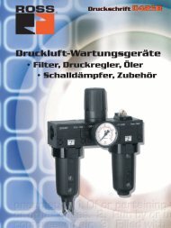
Outlet Port Pressure Moni<strong>to</strong>ring Wiring Kit<br />
Some cus<strong>to</strong>mers prefer <strong>to</strong> moni<strong>to</strong>r downstream pressure in addition <strong>to</strong> using<br />
the DM 2® or DM 1 Series valve. A convenient way <strong>to</strong> do this is <strong>to</strong> install a<br />
pressure switch in the extra outlet port that is provided on the valve. <strong>The</strong><br />
Outlet Port Pressure Moni<strong>to</strong>ring kit can be used with one of the J-Box kits<br />
above <strong>to</strong> split one of the M12 ports on the J-Box so that a pressure switch<br />
can be wired in as well. <strong>The</strong>se kits consist of one port splitter (a Tee with<br />
three M12 connec<strong>to</strong>rs) and one M12-DIN cable (1 meter).<br />
<strong>The</strong> pressure switch is available separately -<br />
order part number 586A86.<br />
See brochure NP011 for more information.<br />
Kit Number 2251H77<br />
O<br />
0.6<br />
(10)<br />
0.4<br />
(17)<br />
0.7<br />
(40) 1.6<br />
(40)<br />
1.6<br />
FEMALE<br />
A<br />
1<br />
2<br />
3<br />
4<br />
5<br />
PORT SPLITTER<br />
5 4 3 2 1<br />
MALE<br />
1<br />
2<br />
3<br />
4<br />
5<br />
FEMALE<br />
B<br />
M12x1 Female<br />
M12x1 Male<br />
3<br />
2<br />
5<br />
4<br />
1<br />
Series SV27 Sensing Valve Wiring Kits<br />
<strong>The</strong>se kits are available in lengths of 4 or 10 meters, with a cord<br />
grip for each cable. <strong>The</strong> kits for solenoid piloted SV27 models<br />
come with 2 cables; one with a 3-pin MINI connec<strong>to</strong>r for the<br />
solenoid and one with a 5-pin M12 (Micro) connec<strong>to</strong>r for the<br />
sensing switch. <strong>The</strong> kits for the air piloted models include only<br />
one cable with a 5-pin M12 connec<strong>to</strong>r for the sensing switch.<br />
(Note: Each cable has one connec<strong>to</strong>r.)<br />
See brochure NP011 for more information.<br />
Kit Number Valve Type Length (meters) No. of Cables<br />
2239H77 Solenoid Pilot 4 2<br />
2240H77 Solenoid Pilot 10 2<br />
2241H77 Air Pilot 4 1<br />
2242H77 Air Pilot 10 1<br />
For Redundant SV27 (CAT 3) Pilot Operated Check valve order 2 kits.<br />
www.rosscontrols.com<br />
23
Safety Clamping Devices<br />
<strong>ROSS</strong> CONTROLS specializes in pneumatic and hydraulic safety solutions.<br />
When needing rod locks, rod brakes or safety catchers <strong>ROSS</strong> will provide you<br />
the optimum solution for every application.<br />
For information or technical assistance please call <strong>ROSS</strong> Technical<br />
Services in the U.S.A. at 1-888-TEK-<strong>ROSS</strong>(835-7677)<br />
Control Reliable Hydraulic Double Valve<br />
Size 12, 16 and 30<br />
A<br />
APPLICATIONS:<br />
• Bending <strong>Machine</strong>s<br />
• Trimming <strong>Machine</strong>s<br />
• Cutting, Forming, Piercing <strong>Machine</strong>s<br />
• Special Purpose Hydraulic Applications<br />
F<br />
E<br />
D<br />
A<br />
P<br />
A<br />
B<br />
T<br />
B<br />
This valve package features redundant valve elements that<br />
allow series flow from the inlet <strong>to</strong> the outlet of the valve<br />
package and allows parallel flow from the outlet <strong>to</strong> tank. This<br />
configuration assures that if either valving element fails <strong>to</strong><br />
operate as requested, inlet flow will be blocked and fluid<br />
from the outlet is directed <strong>to</strong> the tank. <strong>The</strong> shifting of each<br />
valving element is moni<strong>to</strong>red by its own safety switch.<br />
Ports: Inlet: SAE #12 , 16 and 30<br />
Outlet: SAE #12, 16 and 30<br />
Tank: SAE #12, 16 and 30<br />
P<br />
P<br />
T<br />
T<br />
Solenoid Voltage:<br />
12, 24, 48 volts DC<br />
115, 230 voltsAC/60 Hz<br />
For additional information or order placement, consult <strong>ROSS</strong>.<br />
Safety Product Data for SISTEMA Library Users<br />
<strong>ROSS</strong> CONTROLS has available a safety product data library<br />
designed for use with the innovative new Safety Integrity Software<br />
Tool for the Evaluation of <strong>Machine</strong> Applications (SISTEMA).<br />
Developed by the Institute for Occupational Safety and Health of<br />
the German Social Accident Insurance (IFA, formerly know as the<br />
BGIA), SISTEMA is available <strong>to</strong> download for no charge at the<br />
IFA web site. This software <strong>to</strong>ol is expected <strong>to</strong> prove invaluable <strong>to</strong><br />
system designers because of its potential time savings and safety<br />
implications.<br />
Besides having data suitable for use in this world-class system<br />
development <strong>to</strong>ol, <strong>ROSS</strong> CONTROLS is conveniently providing<br />
free library data for a selection of its safety products. <strong>ROSS</strong><br />
expects <strong>to</strong> expand the data offerings in the future.<br />
Currently, data library for the following products are available:<br />
DM2 ® Series C, D and E -Cat-4 double valves, DM1 Series -Cat-3<br />
double valves, 5/2 CrossMirror ® Series -Cat-4 double valves.<br />
<strong>The</strong> <strong>ROSS</strong> DM2 ® Series safety products meet all global<br />
requirements for machine safety and are commonly used for<br />
exhausting the downstream air <strong>to</strong> help meet s<strong>to</strong>p-time requirements<br />
in machine guarding applications.<br />
<strong>ROSS</strong> safety valve cus<strong>to</strong>mers will find convenience and<br />
increased system design accuracy with this free software <strong>to</strong>ol<br />
and data library. It can enhance their overall safety program and<br />
offers a simple way <strong>to</strong> help ensure compliance with the EN ISO<br />
13849-1:2006 standard.<br />
To receive a copy of <strong>ROSS</strong>’ safety product data for the SISTEMA library, email <strong>ROSS</strong> Technical Services at techsvc@rosscontrols.com.<br />
24 © 2011 <strong>ROSS</strong> CONTROLS ® . All Rights Reserved.
Safety & Control Reliability<br />
Your safety system is only as strong as its weakest link. If you are already using safety-rated guard<br />
switches, light curtains, safety mats and e-s<strong>to</strong>ps, and tying them <strong>to</strong> safety relays or PLCs, you have<br />
already acknowledged the need for safety-rated controls. Such electrical safety devices, however, can be<br />
for naught if they are controlling non-safety-rated valves. If there is a solenoid valve that dumps system<br />
air during a safety event, then that valve should have the same safety rating as the rest of the system.<br />
According <strong>to</strong> ISO 13849-1 the Safety Related Portion of the Control System (SRPCS) includes the<br />
pneumatic and hydraulic controls, <strong>to</strong>o.<br />
<strong>ROSS</strong>’ control-reliable DM2 ® valves are rated <strong>to</strong> CAT 4 according <strong>to</strong> the definitions of control categories<br />
in EN954-1:2006 and also rated <strong>to</strong> Performance Level e according <strong>to</strong> ISO 13849-1. Think of these valves<br />
as pneumatic safety modules (relays).<br />
Productivity<br />
Single-point Lockout systems can be an effective way <strong>to</strong> enhance worker safety as well as improve<br />
productivity. Large production equipment often have several LOTO points, with corresponding “commute<br />
times” between these points. <strong>The</strong>refore, an alternative method of LOTO or Single-point Lockout system<br />
can reduce the time <strong>to</strong> perform LOTO and further reduces the likelihood that a LOTO point might be<br />
overlooked. Because the procedure is simpler with a single-point LOTO, there is less risk of someone<br />
choosing <strong>to</strong> skip one or more LOTO points <strong>to</strong> save time.<br />
A single-point lock-out system consists of multiple, keyed, remote LOTO stations situated at work areas<br />
around the machine, and any of these stations alone can lock out the entire zone or machine. As such,<br />
a single lock-out safely disables air power, without any delay due <strong>to</strong> commute time between LOTO points.<br />
Every remote station is constantly sensed by a control-reliable system including safety PLC and controlreliable<br />
valves and contac<strong>to</strong>rs which effectively shut off the energy <strong>to</strong> the areas of the machine <strong>to</strong> be accessed.<br />
safety<br />
Designing <strong>to</strong>ward Zero-Harm.<br />
productivity<br />
Designing <strong>to</strong> maximize<br />
return on investment.<br />
One company was able <strong>to</strong> reduce the time required for their LOTO procedure by 5 minutes. Since this particular machine<br />
averaged 8 jams per shift, they gained 40 minutes of production time per shift or 2 hours per day over 3 shifts.<br />
Note that LOTO equipment and procedures must still be in place for all maintenance tasks that do not meet these exceptions.<br />
A full-size exhaust port, equal <strong>to</strong> or larger than supply, is a requirement of the ANSI B11.0 GSR and PMMI B155.1-2010 standard for<br />
energy isolation devices. This is good for personnel safety in that they can expect the valve <strong>to</strong> exhaust the downstream air at least as fast<br />
as it gets supplied. A huge benefit of this for production is that in productivity. Why? Because the time <strong>to</strong> lockout and exhaust can be<br />
greatly reduced, especially when compared <strong>to</strong> the exhaust capability of a ball valve that at best has a 1/16” diameter exhaust port even<br />
on a 1” ported valve. Exhausting a cubic foot of air at 90 psig with a 1” ported L-O-X ® valve (with full size exhaust port) can take only 1.2<br />
seconds whereas exhausting the same amount of air with a similarly sized ball valve can take 4 minutes. That’s 200 times longer with<br />
the ball valve. How much is 4 minutes of machine “up time” per lockout worth?<br />
Energy Savings<br />
<strong>The</strong> critical workload on most pneumatic cylinder applications is in one direction only. <strong>The</strong> required air<br />
pressure and size of the cylinder is based on this “worst case” scenario. This same pressure level is<br />
applied <strong>to</strong> retract the cylinder as well even though that pressure is usually not needed because there is<br />
no real load being moved in that direction. By reducing the pressure applied during the retract stroke, the<br />
<strong>ROSS</strong> EnergySaver ® valve can save you as much as 30% on compressed air costs for that application.<br />
Leaks in compressed air systems are also a huge source of energy waste. Most leaks occur at joints in<br />
the piping/tubing. <strong>ROSS</strong>’ modular assemblies replace these joints with O-ring seals, which significantly<br />
reduce the normal leak points that are found in most systems, thus reducing the cost of operation over the<br />
life of the system. Leaks cost you $$ even when the system is not running!<br />
Also, using the <strong>ROSS</strong> L-O-X ® valve with positive on/off construction is a good way <strong>to</strong> prevent unwanted air<br />
from flowing downstream as opposed <strong>to</strong> ball valves or slide type shut-off valves that provide no feedback<br />
that they are fully in the desired “on” or “off” position. <strong>The</strong> <strong>ROSS</strong> L-O-X ® valve has a positive detent, so<br />
that you know when the valve is fully shifted. How often have you seen a ball valve that, upon closer<br />
inspection, you find is not quite fully on or off? --- wasting energy and valuable $$$$<br />
Technology<br />
<strong>ROSS</strong>/FLEX ® Expands with New Dale Series<br />
Utilizing the revolutionary new Dale cartridge style poppet valve, the <strong>ROSS</strong>/FLEX ® engineering team<br />
has greatly expanded their capabilities <strong>to</strong> meet the requirements of even the most demanding applications.<br />
A cost-effective <strong>ROSS</strong>/FLEX ® manifold solution can greatly reduce assemble time, minimize the space<br />
required, and alleviates the need for complex and lengthy trouble shooting in the field.<br />
environment<br />
Designing <strong>to</strong> save<br />
energy and reduce<br />
greenhouse gases.<br />
technology<br />
Designing <strong>to</strong> optimize<br />
reduction processes<br />
and applications.<br />
www.rosscontrols.com<br />
25
Safety-related Solutions<br />
<strong>ROSS</strong> Safety-related Solutions<br />
<strong>ROSS</strong> has been manufacturing fluid power products since 1920. In 1954, <strong>ROSS</strong> patented the first double valve<br />
for the most demanding of safety applications: metal forming press clutch and brake control. Since that time,<br />
<strong>ROSS</strong> has patented several improved versions of the double valve and expanded its safety product offering.<br />
<strong>ROSS</strong> has become recognized as the premier supplier of high-quality pneumatic and hydraulic safety<br />
components for various applications in metal forming.<br />
• Control-reliable solenoid operated pneumatic valves<br />
• L-O-X ® lockout and exhaust pneumatic energy isolation valves<br />
• EEZ-ON ® soft start pneumatic valves<br />
• Pilot-operated pneumatic check valves with pressure release<br />
• HOZE-FUZE ® air hose blow-out protection<br />
• Latching manual valves<br />
Double Valves with<br />
Dynamic Moni<strong>to</strong>ring &<br />
Memory<br />
Critical Application<br />
5-Way Solenoid Valve<br />
with Pressure Switch<br />
Lockout Isolation &<br />
Visual Verification<br />
Critical Application<br />
Control-Reliable Valve<br />
Load Holding<br />
SV27 PO Check<br />
with Sensing<br />
DANGER<br />
HIGH<br />
VOLTAGE<br />
Hose Failure<br />
Protection<br />
Hydraulic<br />
Double Valve<br />
2 26 © 2007 2011 <strong>ROSS</strong> CONTROLS ® . ® All . All Rights Reserved.
Safety-related Solutions<br />
<strong>Pneumatic</strong> Solutions <strong>to</strong> Complete your Safety System<br />
<strong>ROSS</strong> CONTROLS Helps You Address ANSI/PMMI B155.1-2006<br />
Requirements with Control Reliable, Energy Isolation Valves<br />
DM 2® Series E <strong>Pneumatic</strong> Valves<br />
Air Dump/Release<br />
Category<br />
3 & 4<br />
Applications<br />
E-s<strong>to</strong>p<br />
Safety relays<br />
Safety PLCs<br />
Safety<br />
Mats<br />
<strong>Light</strong><br />
Curtains<br />
Area<br />
Scanners<br />
“Electrical Interlocks”<br />
(gates, guards, etc.)<br />
Safety-related <strong>Pneumatic</strong>s Products:<br />
• Energy isolation valves for Lockout<br />
• Electrical / <strong>Pneumatic</strong> Energy Isolation (LOTO)<br />
• Load-holding valves<br />
• Soft start Lockout-Tagout<br />
• Cylinder Return <strong>to</strong> Home Position<br />
• Minimize Hose Whip<br />
• Exhaust Noise Reduction<br />
• Wash-Down Applications Cabinets<br />
Stainless Steel L-O-X ®<br />
for Energy Isolation<br />
E-mail: sales.info@rosscontrols.com<br />
<strong>Pneumatic</strong><br />
Lockout and Safety<br />
Exhaust Valve Cabinet for<br />
Wash-Down<br />
www.rosscontrols.com<br />
27
General Illustration - Safety-related Applications<br />
<strong>ROSS</strong> Safety-related Applications<br />
* Cylinder hazard in 2 directions<br />
* Pinch points<br />
* Tooling or product damage<br />
* Single Point Lockout<br />
* Press clutch/brake<br />
* Counterbalance<br />
* Moni<strong>to</strong>red power systems<br />
* Partial de-energization<br />
* Vertical loads<br />
* Cylinder hazard in one direction<br />
* Load holding<br />
L-O-X ® Valve<br />
3 1<br />
Control Reliable<br />
Double Valve<br />
Cat 4 Alternative Method LOTO<br />
2<br />
* Cylinder hazard in 2 directions<br />
* Cylinder mid-stroke positioning<br />
Cat 2 Alternative Method LOTO<br />
* Two-hand control<br />
* Energy isolation<br />
* EEZ-ON ® gradual pressure build-up<br />
* Noise reduction<br />
* 2-hand anti-tie-down machine start<br />
3 1<br />
2<br />
SV27<br />
Sensing Valve<br />
* Hose and/or fitting failure<br />
Two Hand<br />
Control<br />
DISCLAIMER<br />
<strong>The</strong>se circuits are illustrative only and<br />
not intended <strong>to</strong> be used literally for your<br />
application. Each machine is unique<br />
and has individual characteristics that<br />
must be considered when designing a<br />
safety circuit. In addition, the referenced<br />
standards are not an exhaustive list.<br />
<strong>The</strong>re may be many additional local, state,<br />
national, and international standards<br />
as well as machine function specific<br />
standards pertinent <strong>to</strong> your machine.<br />
This document is not a substitute for a<br />
complete risk assessment of a machine’s<br />
hazards, professional circuit design or<br />
acquiring an in depth understanding<br />
of standards/regulations relevant <strong>to</strong> an<br />
application or machine.<br />
FRL Service Shu<strong>to</strong>ff<br />
External Drain<br />
Filter<br />
Regula<strong>to</strong>r Gauge<br />
Silencer<br />
L-O-X ® Valve or<br />
L-O-X ® Valve with<br />
EEZ-ON ® Function<br />
28 © 2011 <strong>ROSS</strong> CONTROLS ® . All Rights Reserved.
General Illustration - Safety-related Applications<br />
5/2 Double Valve<br />
4<br />
Various Safety-related Standards<br />
that Apply <strong>to</strong> Air Systems:<br />
2<br />
ANSI/ASSE Z244.1-2003 (R2008)<br />
Lockout/Tagout Control of Hazardous Energy<br />
Control Reliable<br />
Double Valve<br />
3 1<br />
2<br />
Clutch<br />
OSHA 29 CFR 1910.147,<br />
ANSI B11.0-2010<br />
RIA 15.06<br />
ISO13849<br />
<strong>Machine</strong> <strong>Safeguarding</strong><br />
Brake<br />
ANSI/PMMI B155.1-2010<br />
Safety Requirements for Packaging <strong>Machine</strong>ry<br />
ANSI B11.1<br />
Safety Requirements for Mechanical Power Presses<br />
ANSI B11.2<br />
Safety Requirements for Hydraulic Power Presses<br />
Redundant PO Check Valve<br />
ANSI B11.3<br />
Safety Requirements for Power Press Brakes<br />
EEZ-ON ® Valve<br />
Dual PO Check Valve<br />
ANSI B11.19-2010<br />
Performance Requirements for <strong>Safeguarding</strong> (S<strong>to</strong>p Time)<br />
ANSI B11.TR6-2010<br />
Safety Control Systems for <strong>Machine</strong> Tools<br />
OSHA 29 CFR 1910.211-219<br />
<strong>Safeguarding</strong> Mechanical Power Presses<br />
Flow Control<br />
Control Valve<br />
HOZE-FUZE ®<br />
www.rosscontrols.com<br />
29
A Global Snapshot of Fluid Power and Safety<br />
Valves enhance machine and worker safety<br />
Critical-application safety valves are functionally redundant, self moni<strong>to</strong>ring, and return <strong>to</strong> a safe position.<br />
It is easy <strong>to</strong> say that “Safety is everyone’s goal”, but what is really meant by that? Sound workplace safety practices can reduce the<br />
risk of injury <strong>to</strong> not only machine opera<strong>to</strong>rs but <strong>to</strong> other people such as maintenance technicians; it can also reduce the risk that there is<br />
accidental damage <strong>to</strong> machinery and other company assets, or harm <strong>to</strong> the environment. Common industry standards acknowledge that<br />
there is no such thing as zero risk, while nonetheless providing guidance <strong>to</strong> machine builders and opera<strong>to</strong>rs regarding how <strong>to</strong> take steps <strong>to</strong><br />
minimize risks. This is commonly referred <strong>to</strong> as machine safeguarding. Here’s a look at some key fac<strong>to</strong>rs.<br />
Control Integrity<br />
<strong>The</strong> most important point in machine safeguarding is in evaluating the entire system and not just the electrical portion <strong>to</strong> minimize<br />
exposure <strong>to</strong> unnecessary risk. That’s because systems are rated based on the weakest link in the control chain.<br />
Several standards (including ISO 13849-1:2006, ANSI/ASSE Z244.1-2003 (R2008) and ANSI/PMMI B155.1-2006) define the control<br />
system as including not only input, sensing, and interlock devices but also output devices such as pneumatic and hydraulic valves.<br />
<strong>The</strong> function of a fluid control valve mimics that of an electrical-control relay and, therefore, is subject <strong>to</strong> the same rules for classifying<br />
safety integrity. Thus, properly specified machine safeguarding systems include provisions for pneumatic valves, including:<br />
• Must be functionally redundant<br />
• Must be moni<strong>to</strong>red for faults ( including diminished performance faults which may create the loss of redundancy), without depending<br />
on external machine controls or safety circuitry<br />
• Must return <strong>to</strong> a safe position in the event of a loss of pressure or other such event<br />
• Able <strong>to</strong> inhibit further operation upon detection of a fault condition until such condition is corrected<br />
• Should have a dedicated, specific function-reset input and should prohibit the ability <strong>to</strong> perform a reset by simply removing or reapplying<br />
pneumatic or hydraulic power<br />
• Must not au<strong>to</strong>matically reset<br />
Control reliability is generally considered safety Category-3 or -4 as defined in ISO 13849-1/ EN954-1 Standard for all types of circuits.<br />
This ISO standard regarding Category-3 states ”a single fault in any of these parts does not lead <strong>to</strong> the loss of the safety function” and that<br />
“a fault shall be detected at or before the next demand upon the safety function.” According further <strong>to</strong> this ISO standard for Category-4,<br />
“an accumulation of undetected faults shall not lead <strong>to</strong> the loss of the safety function.”<br />
Providing control reliability with fluid power is not quite the same as with electrical controls, however. For instance, plain redundancy in<br />
a safety circuit requires the equivalent function of four valve elements, not just two. Two of the four valve element handle the inlet function<br />
while the other two elements handle the s<strong>to</strong>p function (energy release). Many self-designed systems risk having hidden, potential flaws,<br />
which can lead <strong>to</strong> unsafe conditions because they are unseen, unexpected and, therefore, excluded from design and safety reviews.<br />
A good example is the spool cross-over conditions or ghost positions of a valve, which are usually not shown on schematics.<br />
Two general abnormal conditions can affect valve safety. <strong>The</strong> first is similar <strong>to</strong> an electrical-control fault, such as when a relay might<br />
be stuck in the open or closed position. <strong>The</strong> second abnormal condition is when a valve develops diminished performance, as when a<br />
valve becomes sticky or sluggish. In these cases the valve reaches the proper position, but slower shifting affects safe s<strong>to</strong>pping distances<br />
or precise timing. <strong>The</strong> ANSI B11.19-2010 Standard mandates a moni<strong>to</strong>ring system that detects these conditions for critical applications<br />
and the ANSI/PMMI B155.1-2010 Standard requires diminished performance moni<strong>to</strong>ring if s<strong>to</strong>pping time can be affected. An easy<br />
solution is <strong>to</strong> use a self-moni<strong>to</strong>ring, Category-3 or -4 valve, designed <strong>to</strong> detect both conditions.<br />
<strong>The</strong> use of double valves remained relatively unheard of for many years except in a few select industries, such as stamping presses,<br />
which first initiated control reliability requirements. Double valves provide dual internal functions (redundancy) so that an abnormal<br />
function of one side of the valve does not interfere with the overall normal operation. At the same time, the double valves sense abnormal<br />
operation on either side of the valve and then inhibit further operation until the problem has been corrected and the valve deliberately<br />
reset. This sensing and inhibiting function is commonly referred <strong>to</strong> as moni<strong>to</strong>ring.<br />
Two standard air valves, whether in parallel or in series, cannot perform the same safeguarding function as does a double valve<br />
critical function. By simply incorporating two standard air valves in<strong>to</strong> the circuit, no provision is made <strong>to</strong> sense the abnormal operation<br />
of one side of the valve or, even more preferable, diminished performance such as slow shifting. In addition, there is no provision for<br />
inhibiting further operation of the circuit until the valve is repaired. If one valve actuates abnormally, the second one continues <strong>to</strong> function<br />
and redundancy is lost. <strong>The</strong> circuit doesn’t recognize lost redundancy nor would it halt operations as a warning that redundancy has been<br />
compromised. <strong>The</strong>n, if the second valve also actuates abnormally, there is no “back up” and control integrity no longer exists.<br />
Double valves are appropriate for pneumatic and hydraulic equipment anytime reliability is an issue. Typical applications include<br />
E-s<strong>to</strong>p, two-hand-control, light curtains, safety gates, pneumatic locking devices for safety gates, hydraulic brakes, air brakes, amusement<br />
rides, hoists, eleva<strong>to</strong>rs, pinch-point applications, or any other application where control system integrity depends on valve operation.<br />
Energy isolation<br />
Lockout/tagout (LOTO) is another high-priority safety <strong>to</strong>pic. Under standard LOTO, before a worker can enter a protected area of a<br />
machine, all energy must be dissipated and machine-status verified. <strong>The</strong> standards define the “de-energized” state as existing when all<br />
energy sources are disconnected from the machine and there are not any circuits containing residual s<strong>to</strong>red energy. For fluid power, this<br />
requires a manually operated energy-isolation valve that must:<br />
• Have a secure and tamper-resistant method of lock attachment<br />
• Be located outside the protected area in an easily accessible location<br />
• Have a method for employees <strong>to</strong> verify energy dissipation prior <strong>to</strong> entering the protected area<br />
• Not be used in normal production<br />
• Have a full-size exhaust port (ANSI/PMMI B155.1-2010, CSA Z142-02)<br />
• Be positive acting (only two possible positions)<br />
• Be easily identifiable<br />
• Can only be locked in the off position<br />
230 © 2007 2011 <strong>ROSS</strong> CONTROLS ® . ® All . All Rights Reserved.
Alternative lockout<br />
<strong>The</strong> ANSI/ASSE Z244.1-2003 (R2008) standard also addresses other lockout techniques, called alternative methods of controls.<br />
<strong>The</strong>se systems can save costs and improve machine up time. But alternative methods controls only apply <strong>to</strong> routine, repetitive tasks<br />
that are integral <strong>to</strong> the production process and are based on risk assessment providing effective personal protection. <strong>The</strong> machine must<br />
still have a standard lockout system for repairs and other tasks.<br />
Alternative methods of controls offer two time-saving advantages. First, it uses a single lock-point (a remote, low-voltage system) that<br />
simplifies and speeds lockout, and enhances safety by avoiding the chance of a point being missed. <strong>The</strong> opera<strong>to</strong>r need not travel all around<br />
the machine <strong>to</strong> access various points <strong>to</strong> lockout or unlock operations. <strong>The</strong>se systems place electrical lockout switches, connected <strong>to</strong> the<br />
control system, at locations that require machine access, and incorporate appropriate safety valves for pneumatic and hydraulic lockout.<br />
<strong>The</strong> second feature of alternative lockout systems is that not all energy needs <strong>to</strong> be removed. In fact, sometimes removing all the energy<br />
creates a more-hazardous condition. This can result in significant time and cost savings when systems contain large volumes of compressed air.<br />
<strong>The</strong> standard is also useful for tasks that are not routine, repetitive, or integral <strong>to</strong> production, but require power for, say, troubleshooting<br />
a control circuit. <strong>The</strong> new standard recognizes that there is no such thing as zero risk, and that some risk is present in order <strong>to</strong> perform<br />
certain tasks. In this case, the standard requires that the control system and valve controlling the non-isolated energy be control-reliable,<br />
Category-3 or -4.<br />
Risk reduction<br />
<strong>The</strong>re is no such thing as “zero risk”. <strong>The</strong>refore, the standards require that you assess all possible risks, and determine what possible<br />
ways can be accomplished for most-effectively reducing those risks.<br />
<strong>The</strong> best approach <strong>to</strong> risk assessment is as a team. One big change ANSI B11.0-2010 brought about is that both the machine manufacturer<br />
and user are responsible for performing the assessment for new and rebuilt machines. In the past, machine safety was considered the user’s<br />
responsibility.<br />
Perhaps the most difficult part is defining the subjective words for the assessment. <strong>The</strong>re are no precise answers, and even the standards<br />
differ. Users need <strong>to</strong> develop their own risk assessment program.<br />
Many companies hold that there are two degrees of injury: minor and major. Minor injuries can be treated with a first aid kit, and anything<br />
requiring more extensive care is considered a major injury for risk assessment purposes.<br />
When a company uses a risk matrix that leans <strong>to</strong>ward the “better-<strong>to</strong>-be-safe” side, the first question is, of course, “Will it entail additional<br />
expense <strong>to</strong> eliminate a rare possibility?” But <strong>to</strong> error on the high side forces the assessment team <strong>to</strong> look more carefully at each hazard.<br />
Often, safety can pay back in machine up time, reduced employee absenteeism, saving the time and cost <strong>to</strong> investigate an accident, insurance<br />
savings, and other hidden costs involved with accidents. Safety is part of a company’s loss-prevention program.<br />
Avoiding using the wrong category valve should be the primary concern when performing a risk assessment. For example, a circuit with<br />
a single valve that suffers a broken spring or a sticky spool would have a different fault result than a similar circuit employing a double valve<br />
experiencing a broken spring or sticky valve. ANSI B11.0-2010 sets the recommended minimum level of control integrity as follows.<br />
Highest degree of risk reduction. Control systems having redundancy with continuous self-checking <strong>to</strong> ensure continuous performance.<br />
High/intermediate risk reduction. Control systems having redundancy with self-checking upon startup.<br />
Low/intermediate risk reduction. Control systems having redundancy that may be manually checked.<br />
Lowest degree of risk reduction. Hydraulic or pneumatic devices and associated control system using single-channel configuration.<br />
Here are a few areas which are commonly considered during an assessment for safety and risk reduction in fluid power.<br />
1. Hydraulic accumula<strong>to</strong>r dump valves, which must be moni<strong>to</strong>red or manually operated<br />
2. Pilot operated check valves (PO checks), which are designed <strong>to</strong> hold a load in place and inherently trap pressure (which<br />
must be released during lockout procedures)<br />
3. Use of 3-position all ports blocked valves, which trap pressure<br />
4. Hazard created when a hose or tube fitting blows off<br />
5. Sudden surge of compressed air being reapplied after LOTO, causing cylinders <strong>to</strong> move quickly and subjecting the machine <strong>to</strong> shock<br />
For all of these, and more, a complete analysis of the circuit should be taken <strong>to</strong> uncover potential hazards, even though the hazards<br />
have never occurred in the past.<br />
<strong>The</strong> standards say if it can happen, it must be considered.<br />
To design a control reliable circuit, the engineer must be able <strong>to</strong> break the reliability chain in<strong>to</strong> links. Each link must represent a<br />
control device that meets the control reliability specifications listed above. If the device does not meet all these criteria, it is not considered<br />
a control device but only a component for integration in<strong>to</strong> a circuit, thus requiring additional components or requiring even a redesign <strong>to</strong><br />
achieve control reliability.<br />
Updating a system may not be difficult if the electrical controls are already control reliable. Because some valves have all of the<br />
moni<strong>to</strong>ring logic built right in, there is no need <strong>to</strong> modify existing external control circuitry for valve moni<strong>to</strong>ring. Simply replacing existing<br />
pneumatic or hydraulic valves with critical-application valves and properly wiring them in<strong>to</strong> the existing system may easily bring the fluid<br />
controls in<strong>to</strong> a control-reliable performance state.<br />
So, the next time you design a circuit, remember that the ANSI, OSHA, ISO, and consensus standards apply <strong>to</strong> the entire control<br />
circuit from beginning <strong>to</strong> end and you will not break the chain.<br />
Additional resources<br />
<strong>ROSS</strong> Controls offers an expanded technical reference book, “Fluid Power Safety for <strong>Machine</strong> Guarding,” a “Risk Loca<strong>to</strong>r for <strong>Machine</strong>ry<br />
with <strong>Pneumatic</strong> Power” CD-ROM, and a course in Fluid Power Safety. TOTAL MACHINE SAFETY. For more info, visit www.rosscontrols.com.<br />
Design Standards and Certifications<br />
<strong>ROSS</strong> valves for Safety-related applications are designed <strong>to</strong> meet many Global standards including the following:<br />
CSA, Australian AS, EN, ISO, OSHA, ANSI, & CE<br />
When required, <strong>ROSS</strong> products can be tested and certified by the following authorities:<br />
UL, CSA, TUV, BG<br />
Please visit www.rosscontrols.com for detailed technical information about any product contained in this brochure. Products<br />
containing the <strong>ROSS</strong> CONTROLS ® safety logo are certified by <strong>ROSS</strong> <strong>to</strong> be engineered and designed for safety-related applications.<br />
www.rosscontrols.com<br />
31
GLOBAL Reach with a LOCAL Touch sm<br />
BULLETIN 510<br />
<strong>ROSS</strong> CONTROLS<br />
Troy, MI., U.S.A.<br />
Telephone: + 1-248-764-1800<br />
Fax: + 1-248-764-1850<br />
In the United States:<br />
Cus<strong>to</strong>mer Service: 1-800-GET <strong>ROSS</strong><br />
(438-7677)<br />
Technical Service: 1-888-TEK-<strong>ROSS</strong><br />
(835-7677)<br />
www.rosscontrols.com<br />
<strong>ROSS</strong> EUROPA GmbH<br />
Langen, Germany<br />
Telephone: + 49-6103-7597-0<br />
Fax: + 49-6103-74694<br />
Email: info@rosseuropa.com<br />
www.rosseuropa.com<br />
<strong>ROSS</strong> ASIA K.K.<br />
Kanagawa , Japan<br />
Telephone: + 81-427-78-7251<br />
Fax: + 81-427-78-7256<br />
www.rossasia.co.jp<br />
<strong>ROSS</strong> UK Ltd.<br />
Birmingham, United Kingdom<br />
Telephone: + 44-121-559-4900<br />
Fax: + 44-121-559-5309<br />
Email: sales@rossuk.co.uk<br />
<strong>ROSS</strong> SOUTH AMERICA Ltda.<br />
São Paulo, Brazil CEP 09725-020<br />
Telephone: + 55-11-4335-2200<br />
Fax: + 55-11-4335-3888<br />
Email: vendas@ross-sulamerica.com.br<br />
DIMAFLUID s.a.s.<br />
Saint Ouen, France<br />
Telephone: + 33-01-49-45-65-65<br />
Fax: + 33-01-49-45-65-30<br />
Email: dimafluid@dimafluid.com<br />
www.dimafluid.com<br />
<strong>ROSS</strong> CONTROLS (CHINA) Ltd<br />
Shanghai, China<br />
Telephone: + 86-21-6915-7951<br />
Fax: + 86-21-6915-7960<br />
www.rosscontrolschina.com<br />
Your local <strong>ROSS</strong> distribu<strong>to</strong>r is:<br />
<strong>ROSS</strong> CONTROLS INDIA Pvt. Ltd.<br />
Chennai, India<br />
Telephone: + 91-44-2624-9040<br />
Fax: + 91-44-2625-8730<br />
Email: rossindia@airtelbroadband.in<br />
All products sold by <strong>ROSS</strong> CONTROLS are warranted for a one-year period<br />
[with the exception of all Filters, Regula<strong>to</strong>rs and Lubrica<strong>to</strong>rs (“FRLs”) which are<br />
STANDARD WARRANTY warranted for a period of seven years] from the date of purchase <strong>to</strong> be free of<br />
defects in material and workmanship. <strong>ROSS</strong>’ obligation under this warranty is<br />
limited <strong>to</strong> repair or replacement of the product or refund of the purchase price paid solely at the discretion of <strong>ROSS</strong> and provided such product<br />
is returned <strong>to</strong> <strong>ROSS</strong> freight prepaid and upon examination by <strong>ROSS</strong> is found <strong>to</strong> be defective. This warranty becomes void in the event that<br />
product has been subject <strong>to</strong> misuse, misapplication, improper maintenance, modification or tampering.<br />
THE WARRANTY EXPRESSED ABOVE IS IN LIEU OF AND EXCLUSIVE OF ALL OTHER WARRANTIES AND <strong>ROSS</strong> EXPRESSLY DISCLAIMS<br />
ALL OTHER WARRANTIES EITHER EXPRESSED OR IMPLIED WITH RESPECT TO MERCHANTABILITY OR FITNESS FOR A PARTICULAR<br />
PURPOSE. <strong>ROSS</strong> MAKES NO WARRANTY WITH RESPECT TO ITS PRODUCTS MEETING THE PROVISIONS OF ANY GOVERNMENTAL<br />
OCCUPATIONAL SAFETY AND/OR HEALTH LAWS OR REGULATIONS. IN NO EVENT IS <strong>ROSS</strong> LIABLE TO PURCHASER, USER, THEIR<br />
EMPLOYEES OR OTHERS FOR INCIDENTAL OR CONSEQUENTIAL DAMAGES WHICH MAY RESULT FROM A BREACH OF THE WARRANTY<br />
DESCRIBED ABOVE OR THE USE OR MISUSE OF THE PRODUCTS. NO STATEMENT OF ANY REPRESENTATIVE OR EMPLOYEE OF<br />
<strong>ROSS</strong> MAY EXTEND THE LIABILITY OF <strong>ROSS</strong> AS SET FORTH HEREIN.<br />
Printed in the U.S.A. - Rev. 07/11 © 2011 <strong>ROSS</strong> CONTROLS ® . All Rights Reserved. Form A10296