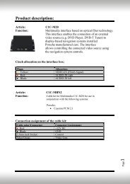
c.LOGiC-Interface C2-MFD2 For navigation ... - vag navisystems
c.LOGiC-Interface C2-MFD2 For navigation ... - vag navisystems
c.LOGiC-Interface C2-MFD2 For navigation ... - vag navisystems

You also want an ePaper? Increase the reach of your titles
YUMPU automatically turns print PDFs into web optimized ePapers that Google loves.
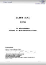
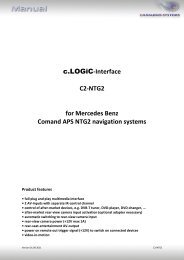
c.<strong>LOGiC</strong>-<strong>Interface</strong><br />
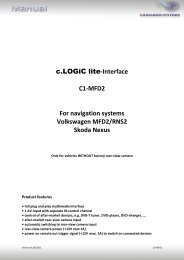
<strong>C2</strong>-<strong>MFD2</strong><br />
<strong>For</strong> <strong>navigation</strong> systems<br />
Volkswagen <strong>MFD2</strong>/RNS2<br />
Skoda Nexus<br />
Only for vehicles WITHOUT factory rear-view camera<br />
Product features<br />
• full plug and play multimedia interface<br />
• 2 AV-inputs with separate IR-control channel<br />
• control of after-market devices, e.g. DVB-T tuner, DVD-player, DVD-changer, …<br />
• after-market rear-view camera input<br />
• automatic switching to rear-view camera input (only from interface mode)<br />
• rear-view camera power (+12V max 1A)<br />
• rear-seat-entertainment AV-output<br />
• power on remote out trigger signal (+12V max 1A) to switch on connected devices<br />
• video-in-motion<br />
Version 01.09.2011<br />
<strong>C2</strong>-<strong>MFD2</strong>
Page1<br />
Contents<br />
1. Prior to Installation<br />
1.1. Delivery contents<br />
1.2. Check compatibility of vehicle and accessories<br />
1.3. Setting the dip switches of the CAN-box TV-400<br />
1.4. Setting the dip switches of the <strong>Interface</strong>-box <strong>C2</strong>C-M200<br />
1.4.1. Automatic switching to rear-view camera<br />
1.4.2. Deactivating c.<strong>LOGiC</strong> AV2-input<br />
2. Connection schema<br />
3. Installation<br />
3.1. Interconnecting <strong>Interface</strong>-box, CAN-box and harnesses<br />
3.2. Connections to head-unit<br />
3.3. Connecting peripheral devices<br />
3.3.1. AV-source(s)<br />
3.3.2. Installing AV-source’s IR-sensor additionally<br />
3.3.3. After-market rear-view camera<br />
3.3.4. After-market rear-seat-entertainment<br />
4. Operation<br />
4.1. Activation of the video-in-motion function<br />
4.2. Selecting the c.<strong>LOGiC</strong> as current AV-source<br />
4.3. Switching between AV1 and AV2<br />
4.4. Assigning device controls<br />
4.5. Button assignment table<br />
4.6. Picture settings<br />
5. Specifications<br />
6. Technical support<br />
Appendix A – Device control table<br />
Version 01.09.2011<br />
<strong>C2</strong>-<strong>MFD2</strong>
Page2<br />
Legal Information<br />
By law, watching moving pictures while driving is prohibited, the driver must not be<br />
distracted. We do not accept any liability for material damage or personal injury resulting,<br />
directly or indirectly, from installation or operation of this product. This product should only<br />
be used while standing or to display fixed menus or rear-view-camera video when the<br />
vehicle is moving, for example the MP3 menu for DVD upgrades.<br />
Changes/updates of the vehicle’s software can cause malfunctions of the interface. We offer<br />
free software-updates for our interfaces for one year after purchase. To receive a free<br />
update, the interface must be sent in at own cost. Labor cost for and other expenses<br />
involved with the software-updates will not be refunded.<br />
1. Prior to installation<br />
Read the manual prior to installation. Technical knowledge is necessary for installation. The<br />
place of installation must be free of moisture and away from heat sources.<br />
1.1. Delivery contents<br />
Take down the SW-version and HW-version of the interface boxes, and store this<br />
manual for support purposes.<br />
CAN-box<br />
TV-400<br />
HW_____<br />
SW _____<br />
Harness<br />
C3C-VW02<br />
<strong>Interface</strong>-box<br />
<strong>C2</strong>C-M200<br />
HW_____ SW_____<br />
If remote function for the connected devices shall be used, additional an IR-<br />
remote cable and Y-adapter are needed, see chapter AV-source(s).<br />
Version 01.09.2011<br />
<strong>C2</strong>-<strong>MFD2</strong>
Page3<br />
1.2. Check compatibility of vehicle and accessories<br />
Requirements<br />
Vehicle<br />
Navigation<br />
Limitations<br />
Factory-TV-tuner<br />
Volkswagen and Skoda<br />
<strong>MFD2</strong>/RNS2 or Nexus <strong>navigation</strong><br />
Must NOT be installed.<br />
1.3. Setting the dip switches of the CAN-box TV-400<br />
All vehicles<br />
dip 1 ON, dip 2 OFF, dip 3 OFF<br />
1.4. Setting the dip switches of the <strong>Interface</strong>-box <strong>C2</strong>C-M200<br />
The default dip switch settings of the <strong>Interface</strong>-box<br />
need to be changed ONLY if an after-market<br />
rear-view camera shall be connected or if the AV2<br />
of the c.<strong>LOGiC</strong> shall be deactivated. The dip<br />
switches are located inside the <strong>Interface</strong>-box.<br />
<strong>For</strong> changes it is necessary to open the box.<br />
Default settings are:<br />
Dip1 = ON, dip2 = OFF, dip3 = OFF<br />
Note: Instead of dip switches, there might be jumper 1 to 3.<br />
1.4.1. Automatic switching to rear-view camera<br />
If an after-market rear-view camera shall be connected, in order<br />
for the c.<strong>LOGiC</strong> to automatically switch to its camera input<br />
on engaged reverse gear,<br />
set dip2 = ON (up).<br />
dip switches<br />
<strong>Interface</strong>-box<br />
1.4.2. Deactivating c.<strong>LOGiC</strong> AV2-input<br />
If only one AV-source shall be connected to the c.<strong>LOGiC</strong>, we<br />
recommend to disable the AV2-input, to avoid customers switching by<br />
mistake to black/no picture of the AV2-input. In order to disable the<br />
AV2-input of the c.<strong>LOGiC</strong>,<br />
set dip1 = OFF (down).<br />
Version 01.09.2011<br />
<strong>C2</strong>-<strong>MFD2</strong>
Page4<br />
2. Connection schema<br />
Version 01.09.2011<br />
<strong>C2</strong>-<strong>MFD2</strong>
Page5<br />
3. Installation<br />
Switch off ignition and disconnect the vehicle’s battery! If according to factory rules<br />
disconnecting the battery has to be avoided, it is usually sufficient to put the vehicle is<br />
sleep-mode. In case the sleep-mode does not show success, disconnect the battery with a<br />
resistor lead.<br />
Place of installation is behind the head-unit.<br />
3.1. Interconnecting <strong>Interface</strong>-box, CAN-box and harnesses<br />
Plug harness C3C-VW02 into 8pin Molex of CAN-box TV-400.<br />
Plug harness C3C-VW02 into 14pin Molex of <strong>Interface</strong>-box <strong>C2</strong>C-M200.<br />
Plug female 18pin AMP-connector of C3C-VW02 into male 18pin AMP-socket of<br />
<strong>Interface</strong>-box <strong>C2</strong>C-M200.<br />
Version 01.09.2011<br />
<strong>C2</strong>-<strong>MFD2</strong>
Page6<br />
3.2. Connections to head-unit<br />
Remove the head-unit from the dash-board.<br />
Transfer female Quadlock connector from the back of the head-unit to male<br />
Quadlock connector of harness C3C-VW02.<br />
Plug female Quadlock connector of C3C-VW02 into male Quadlock socket of<br />
head-unit.<br />
Plug female 18pin AMP-connector of C3C-VW02 into male 18pin AMP-socket of<br />
head-unit.<br />
Note: If the 18pin AMP-socket of the head-unit is already occupied, the vehicle probably has<br />
a factory rear-view camera or a factory TV-tuner. In case of a factory tuner, it must be<br />
uninstalled: disconnect the female 18pin AMP-connector of the factory harness and<br />
disconnect all wires from the factory TV-tuner. In case of a factory rear-view camera you<br />
have ordered/received the wrong product, call for support.<br />
Version 01.09.2011<br />
<strong>C2</strong>-<strong>MFD2</strong>
Page7<br />
3.3. Connecting peripheral devices<br />
It is possible to connect up to 2 after-market AV-sources, after-market rear-view camera and<br />
rear-seat-entertainment to the c.<strong>LOGiC</strong> interface.<br />
Before final installation of the peripheral devices, we recommend to test-run the c.<strong>LOGiC</strong><br />
functions to detect incompatibility of vehicle, <strong>navigation</strong>, factory accessories or peripheral<br />
devices as soon as possible.<br />
Version 01.09.2011<br />
<strong>C2</strong>-<strong>MFD2</strong>
Page8<br />
3.3.1. AV-source(s)<br />
The c.<strong>LOGiC</strong> interface has the possibility to connect and remotely control by <strong>navigation</strong><br />
buttons up to 2 pre-programmed devices. The device list in the device control table<br />
(Appendix A) shows the pre-programmed remote channels and the related IR-remote cables<br />
STA-xxx which must be ordered separately for the control of the device.<br />
Using the respective STA-xxx IR-control cable, interconnect the blue (yellow) female<br />
3pin AMP connector of harness C3C-VW02 and the IR-port of the AV-source 1 (AVsource<br />
2).<br />
Using an RCA-cable, interconnect the female RCA-port AV1 (AV2) of the <strong>Interface</strong>-box<br />
<strong>C2</strong>C-M200 with the AV-output of the AV-source 1 (AV-source 2).<br />
The pink ACC-output wire (+12V max 1A) of harness C3C-VW02 can be connected to<br />
the ACC-input wires of the connected device to switch it on. It carries +12V when the<br />
head-unit is running.<br />
Version 01.09.2011<br />
<strong>C2</strong>-<strong>MFD2</strong>
Page9<br />
3.3.2. Installing AV-source’s IR-sensor additionally<br />
Additionally to the control via OEM <strong>navigation</strong>, it is possible to install the original IR-sensor<br />
of a connected device. By using the respective Y-adapter (e.g. STA-Y35MM or STA-RJ12) for<br />
the IR-Port of the connected device, the controls of <strong>navigation</strong> AND device’s IR-sensor can be<br />
connected and used simultaneously. Installation of the IR-sensor is recommended as the<br />
controls via <strong>navigation</strong> are limited, and not all functions may be covered.<br />
3.3.3. After-market rear-view camera<br />
Connect the video RCA of the after-market rear-view camera to female<br />
RCA connector R-CAM IN of <strong>Interface</strong>-box <strong>C2</strong>C-M200.<br />
Connect the green wire of C3C-VW02 to the camera power supply (max. 1A)<br />
The green wire is high (+12V) when reverse gear is engaged.<br />
Version 01.09.2011<br />
<strong>C2</strong>-<strong>MFD2</strong>
Page10<br />
3.3.4. After-market rear-seat-entertainment<br />
Using RCA-cables, connect the rear-seat-entertainment to the female RCA-connector<br />
VIDEO OUT of <strong>Interface</strong>-box <strong>C2</strong>C-M200.<br />
Note: As the output is a full output, not shared with the video signal for the<br />
<strong>navigation</strong> system, splitting the video with an RCA Y-cable might give a good enough<br />
picture for two rear-seat-entertainment monitors. If not, or if connecting more than<br />
two monitors, use a video splitter.<br />
4. Operation<br />
4.1. Activation of the video-in-motion function<br />
The video-in-motion function is activated permanently without disturbing the <strong>navigation</strong><br />
performance.<br />
4.2. Selecting the c.<strong>LOGiC</strong> as current AV-source<br />
CD-Version - Push AUX button of head-unit , then select<br />
TV to choose the c.<strong>LOGiC</strong> as current AV-source.<br />
DVD-Version - Push CD button of head-unit, then select<br />
AUX to choose the c.<strong>LOGiC</strong> as current AV-source.<br />
Version 01.09.2011<br />
<strong>C2</strong>-<strong>MFD2</strong>
Page11<br />
4.3. Switching between AV1 and AV2<br />
After selecting the c.<strong>LOGiC</strong> as current AV source, push the right knob for 3 seconds to switch<br />
between AV1 and AV2. Repeat to switch back.<br />
Note: If AV2 is deactivated (see chapter chapter Deactivating c.<strong>LOGiC</strong> AV2 input), it is not<br />
possible to switch to the c.<strong>LOGiC</strong>’s AV2.<br />
4.4. Assigning device controls<br />
After selecting the c.<strong>LOGiC</strong> as current AV source, longpress number “1” key.<br />
The MFD will display “TV 1” and “RC01”. Turn right knob until the devicerelated<br />
IR-code for AV1 as described in device control table (appendix A) is<br />
reached. Press right knob to switch to “TV2” and repeat the procedure for<br />
AV2. Push right knob to confirm the assignment.<br />
If the vehicle has no MFD display in the instrument panel (for example in case<br />
of retrofitted <strong>navigation</strong> systems), you must count the notches when turning<br />
the knob (to the right +1, to the left -1). At the same time, remember that<br />
the starting point is channel RC01 (the first notch to the right is then already<br />
RC02).<br />
Note: The IR-control channel TV1 is preset to RC-Code 41 compatible DVB-T<br />
tuners and TV2 is preset to RC-Code 09 for the usbLiNK.<br />
If the AV2 is deactivated (see chapter chapter Deactivating c.<strong>LOGiC</strong> AV2<br />
input), it is not necessary, nor possible to assign device controls.<br />
4.5. Button assignment table<br />
The button assignment table shows which functions of the connected devices can be<br />
executed by head-unit buttons. Once an AV-input is activated, the head-unit button in the<br />
left column will execute the function described in the corresponding device column. The<br />
function description equals the remote control buttons of the optional c.<strong>LOGiC</strong> remote<br />
control or the additional device. On the additional device the writing may vary (e.g. AV<br />
instead of Source).<br />
Version 01.09.2011<br />
<strong>C2</strong>-<strong>MFD2</strong>
Page12<br />
Headunit<br />
button<br />
DVB-T<br />
Tuner<br />
Button assignment table c.<strong>LOGiC</strong> <strong>MFD2</strong>/RNS2/Nexus<br />
Interner USB DVD-player DVDchanger<br />
iPod®-control<br />
Analog-tuner<br />
1 OK POWER PLAY PLAY PLAY/PAUSE SCAN<br />
2 AV MEDIA AV AV EJECT MODE<br />
3 EPG VOL+ PBC PBC SHUFFLE FM<br />
4 INFO VOL- TITLE TITLE REPEAT DISPLAY<br />
5 SCAN ZOOM ZOOM DISC SCAN<br />
6 MENU SETUP SETUP SETUP LIGHT ADJUST<br />
7 DISPLAY MEDIA DISPLAY DISPLAY DISPLAY<br />
8 AUDIO AUDIO AUDIO AUDIO AUDIO<br />
9 → → → → → CH +<br />
10 ← ← ← ← ← CH -<br />
12 ↓ ↓ ↓ ↓ ↓ VOL -<br />
13 ↑ ↑ ↑ ↑ ↑ VOL +<br />
14 OK OK / PLAY OK OK ENTER MODE<br />
11 EXIT EXIT STOP STOP PLAY MUTE<br />
15 CH - TRACK - TRACK - TRACK - TRACK - CH -<br />
16 CH + TRACK + TRACK + TRACK + TRACK + CH +<br />
Additionally to the head-unit buttons, the steering-wheel buttons UP and DOWN can be<br />
used for remote functions. DOWN-button has the same function as 15 on the head-unit and<br />
UP-button has the same function as 16 on the head-unit.<br />
Version 01.09.2011<br />
<strong>C2</strong>-<strong>MFD2</strong>
Page13<br />
4.6. Picture settings<br />
By pressing the button 17, it is possible to switch between 4:3 and 16:9 picture format.<br />
To enter the picture settings menu longpress button 11.<br />
The picture settings menu always<br />
starts with the brightness settings.<br />
The respective current picture value is<br />
displayed on the instrument panel.<br />
Press the right knob to change from<br />
brightness to colour and contrast<br />
(after contrast, the interface starts again<br />
with brightness).<br />
Turn the right knob to change the<br />
current picture value. To quit the<br />
settings menu press “ESC”-button.<br />
5. Specifications<br />
Operation voltage<br />
10.5 – 14.8V DC<br />
Stand-by power drain<br />