

PowerGrip® GT® Belt Drives
PowerGrip® GT® Belt Drives
PowerGrip® GT® Belt Drives

You also want an ePaper? Increase the reach of your titles
YUMPU automatically turns print PDFs into web optimized ePapers that Google loves.
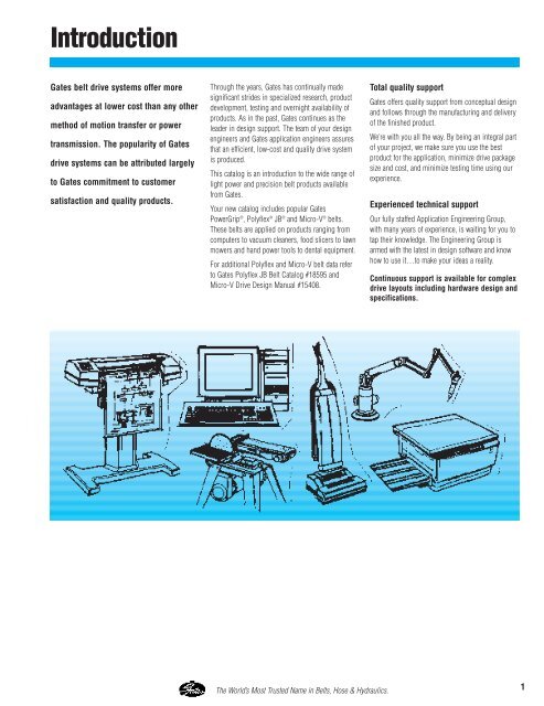
Introduction<br />
Gates belt drive systems offer more<br />
advantages at lower cost than any other<br />
method of motion transfer or power<br />
transmission. The popularity of Gates<br />
drive systems can be attributed largely<br />
to Gates commitment to customer<br />
satisfaction and quality products.<br />
Through the years, Gates has continually made<br />
significant strides in specialized research, product<br />
development, testing and overnight availability of<br />
products. As in the past, Gates continues as the<br />
leader in design support. The team of your design<br />
engineers and Gates application engineers assures<br />
that an efficient, low-cost and quality drive system<br />
is produced.<br />
This catalog is an introduction to the wide range of<br />
light power and precision belt products available<br />
from Gates.<br />
Your new catalog includes popular Gates<br />
PowerGrip ® , Polyflex ® JB ® and Micro-V ® belts.<br />
These belts are applied on products ranging from<br />
computers to vacuum cleaners, food slicers to lawn<br />
mowers and hand power tools to dental equipment.<br />
For additional Polyflex and Micro-V belt data refer<br />
to Gates Polyflex JB <strong>Belt</strong> Catalog #18595 and<br />
Micro-V Drive Design Manual #15408.<br />
Total quality support<br />
Gates offers quality support from conceptual design<br />
and follows through the manufacturing and delivery<br />
of the finished product.<br />
We’re with you all the way. By being an integral part<br />
of your project, we make sure you use the best<br />
product for the application, minimize drive package<br />
size and cost, and minimize testing time using our<br />
experience.<br />
Experienced technical support<br />
Our fully staffed Application Engineering Group,<br />
with many years of experience, is waiting for you to<br />
tap their knowledge. The Engineering Group is<br />
armed with the latest in design software and know<br />
how to use it…to make your ideas a reality.<br />
Continuous support is available for complex<br />
drive layouts including hardware design and<br />
specifications.<br />
The World’s Most Trusted Name in <strong>Belt</strong>s, Hose & Hydraulics.<br />
1
Introduction – PowerGrip ® GT ® <strong>Belt</strong> <strong>Drives</strong><br />
There’s nothing like a good<br />
set of teeth when it comes to<br />
synchronous belts.<br />
PowerGrip ® GT ® <strong>Belt</strong><br />
Tooth/Groove Contact<br />
PowerGrip ® HTD ® <strong>Belt</strong><br />
Tooth/Groove Contact<br />
The advantages of Gates PowerGrip ® GT ®<br />
belt drives are overwhelming<br />
The PowerGrip GT <strong>Belt</strong> Drive System is an advance<br />
in product design over Gates older, standard HTD<br />
system. The PowerGrip GT System, featuring a<br />
modified curvilinear belt tooth profile, provides<br />
timing and indexing accuracy equivalent to the<br />
conventional PowerGrip Trapezoidal <strong>Belt</strong> System.<br />
Plus, PowerGrip GT <strong>Belt</strong>s have a higher capacity<br />
and longer belt life than trapezoidal belts.<br />
It’s difficult to make a true quantitative comparison<br />
between the backlash of a trapezoidal tooth drive<br />
and PowerGrip GT tooth drive due to the difference<br />
in “sprocket to belt tooth” fit. (See illustrations<br />
below). Trapezoidal belts contact the sprocket in the<br />
root radius – upper flank area only, while the<br />
PowerGrip GT system permits full flank contact.<br />
The main stress line in a trapezoidal tooth timing<br />
belt is at the base of the teeth. During operation this<br />
stress greatly reduces belt life. The PowerGrip GT<br />
system overcomes this condition with its complete<br />
tooth flank contact which eliminates the tooth stress<br />
line area. This greatly increases belt life and<br />
prevents tooth distortion caused by drive torque. In<br />
addition, the conventional timing belt has a chordal<br />
effect as it wraps small sprockets. This is<br />
significantly reduced in the PowerGrip GT system<br />
because there’s full tooth support along the<br />
sprocket. Full support improves meshing, reduces<br />
vibration and minimizes tooth deformation.<br />
On drives using a low installation tension, small<br />
pulleys, and light loads, the backlash of the<br />
PowerGrip GT system will be slightly better than the<br />
trapezoidal timing belt system. However, with<br />
increased tension and/or loads and/or sprocket<br />
sizes the performance of the PowerGrip GT system<br />
becomes significantly better than the trapezoidal<br />
timing belt system.<br />
The PowerGrip GT system is an extension of the<br />
HTD system with greater load-carrying capacity.<br />
HTD was developed for high torque drive<br />
applications, but is not acceptable for most<br />
precision indexing or registration applications. The<br />
HTD design requires substantial belt tooth to<br />
sprocket groove clearance (backlash) to perform. As<br />
smaller diameter sprockets are used, the clearance<br />
required to operate properly is increased. HTD drive<br />
clearance, using small diameter sprockets, is<br />
approximately four times greater than an equivalent<br />
timing belt drive.<br />
Deep tooth profile makes the difference<br />
The PowerGrip GT system’s deep tooth design<br />
increases the contact area which provides improved<br />
resistance to ratcheting. The modified curvilinear<br />
teeth enter and exit the sprocket grooves cleanly<br />
resulting in reduced vibration. This tooth profile<br />
design results in parallel contact with the groove<br />
and eliminates stress concentrations and tooth<br />
deformation under load. The PowerGrip GT design<br />
improves registration characteristics and maintains<br />
high torque carrying capability.<br />
PowerGrip ® Timing <strong>Belt</strong><br />
Tooth/Groove Contact<br />
2 The World’s Most Trusted Name in <strong>Belt</strong>s, Hose & Hydraulics.
Introduction – PowerGrip ® GT ® <strong>Belt</strong> <strong>Drives</strong><br />
The choice of the industry for ultimate<br />
durability and precision<br />
Finally, a synchronous belt that fits in all those tight,<br />
hard to fit applications with room to spare.<br />
The Gates PowerGrip GT combines the very best in<br />
technology and construction design to give you<br />
improved performance and extended product life.<br />
Last longer than competitive belts<br />
The PowerGrip GT belt has been tested against the<br />
competition, under equivalent conditions, at speeds<br />
up to 9,000 RPM. It outlasted the competition more<br />
than two to one. Strong fiberglass tensile cords<br />
wrapped in a durable neoprene body gives it<br />
flexibility and increases service life. A deep tooth<br />
profile provides superior load-carrying strength and<br />
greatly reduces ratcheting when used with Gates<br />
designed sprockets.<br />
Precision registration<br />
PowerGrip GT belts provide timing and<br />
synchronization accuracy that make for flawless<br />
registration, with no loss of torque carrying<br />
capability.<br />
Increases load-carrying capacity<br />
Load capacities far exceed HTD and trapezoidal belt<br />
capabilities making PowerGrip GT belts the choice<br />
for accurate registration, heavy loads and small<br />
sprockets. Smaller, yet tougher than HTD or<br />
trapezoidal belts, PowerGrip GT belts give engineers<br />
more space-saving flexibility for the age of microtechnology.<br />
Sounds this quiet…<br />
The PowerGrip GT belt’s specially engineered teeth<br />
mesh cleanly with sprocket grooves to reduce noise<br />
and vibration. Clean meshing and reduced belt<br />
width results in significant noise reduction when<br />
compared to PowerGrip Timing and HTD belts.<br />
When precision is critical, depend on<br />
PowerGrip GT belts<br />
PowerGrip GT belts are specifically designed for<br />
applications where precision is critical. Applications<br />
such as computer printers and plotters, laboratory<br />
and machine tools. We offer belts in a variety of<br />
sizes… custom-built constructions are also<br />
available for individual applications that require<br />
maximum performance. Gates’ worldwide<br />
manufacturing capabilities assure you of prompt<br />
service for important markets.<br />
PowerGrip GT belts are currently available in 2mm,<br />
3mm and 5mm pitches.<br />
PowerGrip GT <strong>Belt</strong> <strong>Drives</strong>. . . . . . . . . . Pages 12-27<br />
Here are just some of the many<br />
applications of PowerGrip GT belts:<br />
■<br />
■<br />
■<br />
■<br />
■<br />
■<br />
■<br />
■<br />
■<br />
■<br />
■<br />
■<br />
■<br />
■<br />
■<br />
■<br />
■<br />
■<br />
■<br />
■<br />
data storage equipment<br />
printers<br />
plotters<br />
machine tools<br />
floor care equipment<br />
copiers<br />
hand power tools<br />
money handling equipment<br />
robotics equipment<br />
postage handling equipment<br />
medical diagnostic equipment<br />
vending equipment<br />
DC stepper/servo applications<br />
sewing machines<br />
vacuum cleaners<br />
food processors<br />
automated teller machines<br />
office equipment<br />
centrifuges<br />
ticket dispensers<br />
The World’s Most Trusted Name in <strong>Belt</strong>s, Hose & Hydraulics.<br />
3
Introduction – PowerGrip ® HTD ® <strong>Belt</strong> <strong>Drives</strong><br />
Good torque carrying capability and design<br />
versatility<br />
PowerGrip HTD drives provide several advantages<br />
over conventional gear and chain type drives. HTD<br />
drives run quiet, do not need lubricating and require<br />
virtually zero maintenance. Plus, the high reliability<br />
and low operating costs of HTD drives are critical to<br />
being competitive in today’s global economy.<br />
Gates 3mm and 5mm pitch HTD belts are capable of<br />
operating at both low and high speeds and carry<br />
heavy loads. They can also provide higher speed<br />
ratios than comparable XL and L pitch timing belts<br />
in the same space. Compared to conventional<br />
timing belts, they can transmit the same power in a<br />
more compact drive package.<br />
These HTD belts have the same characteristics as<br />
larger 8mm and 14mm pitch belts, but are designed<br />
for smaller horsepower and higher speed<br />
requirements.<br />
3mm and 5mm pitch HTD belts provide positive<br />
nonslip power transmission with many advantages<br />
over conventional drive systems.<br />
They can handle tough applications, even those<br />
subject to sudden shock and overloading.<br />
Some PowerGrip HTD <strong>Belt</strong><br />
Applications are:<br />
■<br />
■<br />
■<br />
■<br />
■<br />
■<br />
■<br />
■<br />
■<br />
■<br />
■<br />
floor polishers<br />
vacuum cleaners<br />
sewing machines<br />
sanders<br />
office equipment<br />
planers<br />
centrifuges<br />
diagnostic equipment<br />
power tools<br />
vending machines<br />
juicers<br />
PowerGrip HTD <strong>Drives</strong> . . . . . . . . . . . Pages 28-35<br />
PowerGrip ® Timing <strong>Belt</strong> <strong>Drives</strong><br />
Provide positive, non-slip power<br />
transmission<br />
PowerGrip Timing <strong>Belt</strong>s are a good standard line<br />
product with a history of reliability. Around since the<br />
early 1940’s, this product line has been the flagship<br />
of synchronous power transmission prior to Gates<br />
introduction of PowerGrip HTD and GT <strong>Belt</strong>s.<br />
Gates timing belts are made with a true design<br />
pitch, a standard of the Rubber Manufacturers’<br />
Association and the International Standards<br />
Organization.<br />
PowerGrip Timing <strong>Belt</strong>s are<br />
recommended for these types of<br />
applications:<br />
■<br />
■<br />
■<br />
■<br />
■<br />
■<br />
■<br />
■<br />
■<br />
office equipment<br />
data processing equipment<br />
money handling equipment<br />
miniaturized applications<br />
food processors<br />
mailing equipment<br />
medical equipment<br />
robotics<br />
printers/plotters<br />
PowerGrip Timing <strong>Drives</strong> Pages . . . . . . . . . 36-41<br />
4
Introduction – PowerGrip ® Twin Power ® <strong>Belt</strong><br />
Dual driving surfaces allow for unique,<br />
problem solving drive designs<br />
Gates Twin Power <strong>Belt</strong>s have teeth on both sides to<br />
provide synchronization from both driving surfaces.<br />
This special feature makes possible unique drive<br />
designs such as multipoint drives, rotation reversal<br />
with one belt, serpentine drives, etc. They may also<br />
provide solutions to other difficult design problems.<br />
Twin Power <strong>Belt</strong>s are similar in construction to<br />
regular synchronous belts, including nylon-faced<br />
teeth on both sides. This construction allows for the<br />
use of essentially the same design parameters as<br />
standard synchronous belts. They’re rated at the<br />
same horsepower capacity as conventional<br />
PowerGrip <strong>Belt</strong>s of identical pitch and width on<br />
either side of the belt.<br />
NOTE: Twin Power <strong>Belt</strong>s are available in HTD and<br />
Timing <strong>Belt</strong> configurations, so designers can use<br />
them in a wide variety of applications.<br />
Some typical PowerGrip Twin Power<br />
applications are:<br />
■<br />
■<br />
■<br />
copiers<br />
serpentine drives<br />
reversing rotations<br />
PowerGrip Twin Power <strong>Belt</strong>ing . . . . . . Pages 42-43<br />
PowerGrip ® Long Length <strong>Belt</strong>ing<br />
For drives that require belts lengths longer<br />
than can be produced in conventional<br />
endless form.<br />
Long-length PowerGrip <strong>Belt</strong>ing has the same basic<br />
construction as conventional Gates timing belts.<br />
Gates can make continuous belting in spiral cut<br />
form on a made to order basis.<br />
For information or assistance on any long length<br />
belt problem, contact Gates Application<br />
Engineering.<br />
Typical PowerGrip Long Length <strong>Belt</strong>ing<br />
uses are:<br />
■<br />
■<br />
■<br />
reciprocating carriage drives<br />
rack and pinion drives<br />
large plotters<br />
PowerGrip Long Length <strong>Belt</strong>ing. . . . . . . . . Page 44<br />
The World’s Most Trusted Name in <strong>Belt</strong>s, Hose & Hydraulics.<br />
5
Introduction – Polyflex ® JB ® <strong>Belt</strong> <strong>Drives</strong><br />
Gates Polyflex® JB® is a joined<br />
belt with a different angle<br />
High power density puts more power in<br />
small spaces<br />
“High Power Density” is what you get from this<br />
high-precision belt. Developed by Gates and<br />
produced using patented manufacturing processes,<br />
Polyflex JB belts provide more load-carrying<br />
capacity at higher speeds on precision applications.<br />
Polyflex JB belts can operate at shaft speeds well in<br />
excess of 10,000 rpm’s.<br />
Polyflex JB features joined belt construction for<br />
stability. Backside ribs relieve bending stress on<br />
small sheaves and provide lateral rigidity. The 60 ®<br />
angle provides more undercord support to the<br />
tensile section and distributes the load evenly.<br />
The small cross-section allows belts to be used on<br />
short centers and small diameter sheaves for<br />
“cleaner” machine designs. It virtually eliminates the<br />
need for double-reduction drives and lets you use<br />
more cost effective single-reduction drives.<br />
Gates Polyflex JB belts are a homogenous product.<br />
State-of-the-art manufacturing processes assure<br />
uniformity of construction, resulting in minimal<br />
vibration and smooth operation on precision<br />
applications.<br />
Gates special high modulus polyurethane<br />
compound has a high coefficient of friction that<br />
resists fatigue, wear, ozone and most adverse<br />
environmental conditions.<br />
Cost Savings – PLUS! Polyflex JB belts bring V-<br />
belt economy and simplicity to applications where<br />
conventional V-belts are not feasible, resulting in<br />
cost savings and design freedom never before<br />
possible.<br />
Typical Polyflex JB applications are:<br />
■<br />
■<br />
■<br />
■<br />
■<br />
■<br />
■<br />
■<br />
■<br />
■<br />
■<br />
■<br />
■<br />
■<br />
■<br />
■<br />
■<br />
■<br />
■<br />
■<br />
computer peripherals<br />
bench-type milling machines<br />
glass blowing lathes<br />
valve grinding machines<br />
crankshaft grinding machines<br />
woodworking spindle drives<br />
horizontal milling machines<br />
dental grinders<br />
floor care equipment<br />
microfiche readers<br />
drilling machines<br />
lathe drives<br />
knife grinders<br />
scissor sharpeners<br />
centrifuges<br />
blowers<br />
wheelchairs<br />
optical lens grinders<br />
fans<br />
metalworking spindle drives<br />
Polyflex JB <strong>Drives</strong> Pages . . . . . . . . . . . . . . . 66-68<br />
6 The World’s Most Trusted Name in <strong>Belt</strong>s, Hose & Hydraulics.
Introduction – Micro-V ® <strong>Belt</strong> <strong>Drives</strong><br />
For the best ribs around, look no<br />
further than Gates Micro-V® <strong>Belt</strong>s<br />
Truncated tooth profile increases flexibility<br />
and reduces heat<br />
Gates Micro-V <strong>Belt</strong>s outperform other V-ribbed belts<br />
because the V’s are shorter. The truncated<br />
(shortened) profile of the V’s give Gates Micro-V<br />
<strong>Belt</strong>s increased flexibility, reduced heat buildup and<br />
lets them perform at extra high speeds on smaller<br />
diameter sheaves.<br />
Gates exclusive truncated design is one reason<br />
Micro-V <strong>Belt</strong>s offer up to 80% higher horsepower<br />
capacity than RMA standards. And, extra loadcarrying<br />
capacity means extra long life.<br />
Two more advantages of truncated V’s are that the<br />
belt doesn’t bottom in pulleys and an inherently<br />
greater debris tolerance.<br />
Micro-V <strong>Belt</strong>s are smooth running and resistant to<br />
oil, heat and other adverse conditions. Plus,<br />
undercords are static conductive.<br />
No other V-ribbed belts are built as well as Gates<br />
Micro-V <strong>Belt</strong>s. Gates belts provide you with the<br />
long and reliable service life today’s industry<br />
requires.<br />
Just some of the applications for Micro-V<br />
<strong>Belt</strong>s are:<br />
■<br />
■<br />
■<br />
■<br />
■<br />
■<br />
■<br />
■<br />
■<br />
■<br />
■<br />
■<br />
■<br />
■<br />
■<br />
■<br />
■<br />
■<br />
■<br />
■<br />
■<br />
■<br />
■<br />
■<br />
high speed machine tools<br />
milling lathes<br />
washing machines<br />
precision surface grinders<br />
floor polishers<br />
tool grinders<br />
high speed printing presses<br />
centrifuges<br />
agitators<br />
precision center lathes<br />
pumps<br />
high-speed atomizers<br />
trash compactors<br />
planers and molders<br />
dryers<br />
food slicers<br />
electric massagers<br />
lawn mowers<br />
juice mixers<br />
industrial vacuum cleaners<br />
microwave ovens<br />
bakery equipment<br />
compressors<br />
fans<br />
Micro-V <strong>Drives</strong> Pages . . . . . . . . . . . . . . . . . 69-70<br />
The World’s Most Trusted Name in <strong>Belt</strong>s, Hose & Hydraulics.<br />
7
Drive Comparison Graphs<br />
High Speed Drive<br />
Rating Graph<br />
The following graph contains a representation of<br />
horsepower ratings, over a wide speed range, of the<br />
belt types represented in this catalog. The<br />
sprocket/pulley/sheave diameters and belt widths<br />
are all comparable for a realistic comparison of<br />
product capability.<br />
Rated Horsepower<br />
6<br />
5<br />
4<br />
3<br />
2<br />
1<br />
0<br />
5M HTD<br />
3M HTD<br />
XL Timing<br />
2M PGGT<br />
MXL Timing<br />
5M Polyflex<br />
5M PGGT<br />
J Micro-V<br />
3M PGGT<br />
1 2 4 6 8 10 12 14 16 18 20<br />
Speed (x 1000 rpm)<br />
Low Speed Synchronous Drive<br />
Rating Graph<br />
The following graph provides a comparison of the<br />
rated torque carrying capabilities of synchronous<br />
belts, on small diameter sprockets/pulleys at low<br />
speeds. The sprocket/ pulley diameters and belt<br />
widths are all comparable for a realistic comparison.<br />
Rated Horsepower<br />
0.38<br />
0.30<br />
0.23<br />
0.15<br />
0.08<br />
0<br />
5M HTD<br />
3M HTD<br />
XL Timing<br />
2M PGGT<br />
MXL Timing<br />
5M PGGT<br />
3M PGGT<br />
10 20 40 60 100 200 300 500 700 1000<br />
Speed (rpm)<br />
8 The World’s Most Trusted Name in <strong>Belt</strong>s, Hose & Hydraulics.
Synchronous Drive Comparisons<br />
Designers and engineers find that PowerGrip belt<br />
drives provide exceptional versatility and reliability.<br />
Small and lighter weight drive packages can be<br />
used in a wide variety of applications. PowerGrip<br />
drives also offer efficient operation over a wide<br />
range of loads and speeds.<br />
Drive Package Comparison<br />
Compact, space saving belt drives can be<br />
designed with high-performance drive<br />
systems like PowerGrip GT. As illustrated,<br />
PowerGrip GT drives are significantly<br />
narrower than comparably designed<br />
PowerGrip HTD and PowerGrip Timing <strong>Belt</strong><br />
drives, resulting in space, weight and cost<br />
savings.<br />
3mm PowerGrip GT® <strong>Belt</strong> Drive – 9mm<br />
DriveR: 3MR-30S-09 (1.128 P.D.)<br />
DriveN: 3MR-60S-09 (2.256 P.D.)<br />
<strong>Belt</strong> Width : 9mm<br />
3mm PowerGrip HTD® <strong>Belt</strong> Drive –<br />
15mm<br />
DriveR: P30-3M-15 (1.128 P.D.)<br />
DriveN: P60-3M-15 (2.256 P.D.)<br />
<strong>Belt</strong> Width: 15mm<br />
XL® PowerGrip Timing <strong>Belt</strong> Drive –<br />
22mm<br />
DriveR: 18XL085 (1.146 P.D.)<br />
DriveN: 36XL085 (2.292 P.D.)<br />
<strong>Belt</strong> Width: 22mm<br />
The World’s Most Trusted Name in <strong>Belt</strong>s, Hose & Hydraulics.<br />
9
Synchronous Drive Comparisons<br />
The development of the PowerGrip GT belt has<br />
produced an impressive range of enhanced<br />
properties and subsequent design opportunities for<br />
engineers.<br />
The following comparative studies have been<br />
included to allow designers to make quantitative<br />
assessments and to highlight the most significant<br />
improvements and design opportunities.<br />
Particularly significant points from the following<br />
comparative studies are:<br />
Durability<br />
The greatly increased durability of the PowerGrip GT<br />
design has resulted in power capacities far above<br />
those quoted for similar size belts. The resulting<br />
small drive packages will increase design flexibility,<br />
space utilization and cost effectiveness.<br />
Tooth Jump Resistance<br />
The very significant improvement in tooth jump<br />
resistance of PowerGrip GT when compared to<br />
similar belts has several important advantages.<br />
a. Ratcheting resistance during high start-up torques.<br />
b. Reduced bearing loads, particularly in fixedcenter<br />
drives. Lower average tensions can be used<br />
without encountering tooth jump at the low-tension<br />
end of the tolerance ranges.<br />
c. Reduced system losses result from lower pretensioning,<br />
with less potential for tooth jumping.<br />
Tooth Jump Torque (lb-in)<br />
10<br />
8<br />
6<br />
4<br />
2<br />
® ®<br />
2M PowerGrip GT Versus MXL<br />
2mm PGGT<br />
MXL<br />
Tooth Jump Torque (lb-in)<br />
60<br />
50<br />
40<br />
30<br />
20<br />
10<br />
® ®<br />
3M PowerGrip GT Versus 3M HTD<br />
3mm PGGT<br />
3mm HTD<br />
Tooth Jump Torque (lb-in)<br />
450<br />
375<br />
300<br />
225<br />
150<br />
75<br />
® ®<br />
5M PowerGrip GT Versus 5M HTD<br />
5mm PGGT<br />
5mm HTD<br />
0<br />
1 2 3 4 5<br />
Installed Tension (lb)<br />
TEST CONDITIONS<br />
Speed: 1130 rpm<br />
Pulleys: DriveR 20 grooves<br />
DriveN 20 grooves<br />
<strong>Belt</strong> Width: 4.8mm<br />
0<br />
2 4 6 8 10<br />
Installed Tension (lb)<br />
TEST CONDITIONS<br />
Speed: 750 rpm<br />
Pulleys: DriveR 30 grooves<br />
DriveN 30 grooves<br />
<strong>Belt</strong> Width: 6mm<br />
0<br />
15 30 45 60 75<br />
Installed Tension (lb)<br />
TEST CONDITIONS<br />
Speed: 2300 rpm<br />
Pulleys: DriveR - 20 grooves<br />
DriveN - 20 grooves<br />
<strong>Belt</strong> Width: 15mm<br />
10 The World’s Most Trusted Name in <strong>Belt</strong>s, Hose & Hydraulics.
Synchronous Drive Comparisons<br />
Noise<br />
The smoother meshing action of the PowerGrip GT<br />
belt, with its optimized design produces<br />
significantly lower noise levels when compared with<br />
other, similar sized belt types operating under<br />
similar speeds and tensions. These improvements<br />
are enhanced by the fact that narrower belts can be<br />
used due to increased power capacities.<br />
Positioning Accuracy<br />
.003<br />
.030<br />
The PowerGrip HTD belt tooth forms were primarily<br />
designed to transmit high torque loads. This<br />
requirement increased tooth to groove clearances<br />
which resulted in increased backlash when<br />
compared with the original classical designs.<br />
PowerGrip GT has reversed this with power<br />
capacities now exceeding those of PowerGrip HTD<br />
while giving equivalent or higher levels of positional<br />
accuracy than PowerGrip Timing belts.<br />
Positioning Error (in)<br />
.002<br />
.001<br />
0<br />
2M PGGT<br />
MXL<br />
Application: motion transfer<br />
<strong>Belt</strong>:<br />
Pulleys:<br />
No. of teeth<br />
Width<br />
DriveR<br />
DriveN<br />
126<br />
8mm<br />
12 grooves<br />
40 grooves<br />
Installed tension: 1.8 lb<br />
Motor: 200 steps/cycle<br />
Positioning Error (in)<br />
.020<br />
.010<br />
0<br />
3M PGGT<br />
Application: light load<br />
<strong>Belt</strong>:<br />
Pulleys:<br />
Installed tension:<br />
Motor:<br />
3M HTD<br />
No. of teeth<br />
Width<br />
DriveR<br />
DriveN<br />
6.6 lb<br />
200 steps/cycle<br />
92<br />
6mm<br />
20 grooves<br />
20 grooves<br />
The World’s Most Trusted Name in <strong>Belt</strong>s, Hose & Hydraulics.<br />
11
PowerGrip ® GT ® <strong>Belt</strong> <strong>Drives</strong><br />
<strong>Belt</strong> Construction<br />
PowerGrip GT drives provide positive, trouble-free<br />
power transmission in low speed high torque<br />
applications and offer many advantages over<br />
conventional chain, gear and other belt drives.<br />
3. Neoprene<br />
Teeth<br />
Advantages:<br />
■<br />
■<br />
■<br />
Higher capacity<br />
Improved registration<br />
Reduced noise<br />
4. Nylon<br />
Facing<br />
■<br />
■<br />
■<br />
■<br />
No lubrication required<br />
Minimal elongation due to wear<br />
Corrosion resistance<br />
Excellent abrasion resistance<br />
2. Neoprene<br />
Backing<br />
1. Tensile<br />
Member<br />
■<br />
Clean operation<br />
■<br />
Long trouble-free service<br />
Construction Features<br />
The tooth design substantially improves stress<br />
distribution and allows heavy loading. The molded<br />
teeth enter and leave the sprocket grooves smoothly<br />
with negligible friction – functioning in much the<br />
same way as teeth on a gear.<br />
Construction consists of these components:<br />
1. Tensile Member – Provides high strength,<br />
excellent flex life and high resistance to<br />
elongation.<br />
2. Neoprene Backing – Strong Neoprene<br />
bonded to the tensile member for protection<br />
against grime, oil and moisture. It also protects<br />
from frictional wear if idlers are used on the<br />
back of the belt.<br />
3. Neoprene Teeth – Shear-resistant Neoprene<br />
compound is molded integrally with the<br />
Neoprene backing. They are precisely formed<br />
and accurately spaced to assure smooth<br />
meshing with the sprocket grooves.<br />
➀<br />
➁<br />
4. Nylon Facing – Tough nylon fabric with a low<br />
coefficient of friction covers the wearing<br />
surfaces of the belt. It protects the tooth<br />
surfaces and provides a durable wearing surface<br />
for long service.<br />
➂<br />
➃<br />
12 The World’s Most Trusted Name in <strong>Belt</strong>s, Hose & Hydraulics.
PowerGrip ® GT ® <strong>Belt</strong> <strong>Drives</strong><br />
Gates 2mm, 3mm and 5mm pitch PowerGrip GT<br />
belts have helically-wound fiberglass tension<br />
members embedded in a Neoprene body with the<br />
belt teeth faced with a tough wear-resistant nylon<br />
fabric.<br />
As shown below, three principal dimensions of a<br />
belt (Pitch, Pitch Length and Width) in millimeters<br />
are used to specify a PowerGrip GT belt:<br />
3MR 300 09<br />
Pitch Pitch Length Width<br />
<strong>Belt</strong> pitch is the distance in millimeters between two<br />
adjacent tooth centers as measured on the pitch line<br />
of the belt. <strong>Belt</strong> pitch length is the total length<br />
(circumference) in millimeters as measured along<br />
the pitch line. The theoretical pitch line of a GT belt<br />
lies within the tensile member.<br />
Three principal dimensions of a sprocket – number<br />
of grooves, pitch and belt width in millimeters are<br />
used to specify a PowerGrip GT sprocket as shown<br />
below:<br />
3MR 22S 09<br />
Pitch Number of Grooves <strong>Belt</strong> Width<br />
Pitch<br />
Diameter<br />
Pitch (circular pitch)<br />
Outside<br />
Diameter<br />
<strong>Belt</strong><br />
Pitch<br />
Line<br />
Sprocket<br />
Pitch<br />
Circle<br />
PowerGrip GT drives have a higher load capacity<br />
than PowerGrip HTD and PowerGrip Timing drives.<br />
They also feature equivalent or better backlash<br />
characteristics when compared to PowerGrip Timing<br />
drives. These attributes make PowerGrip GT the<br />
drive of choice for today’s design engineers.<br />
PowerGrip ® GT ® belts must run in PowerGrip ® GT ®<br />
sprockets. PowerGrip GT belts are not compatible<br />
with PowerGrip ® HTD ® sprockets.<br />
The World’s Most Trusted Name in <strong>Belt</strong>s, Hose & Hydraulics.<br />
13
PowerGrip ® GT ® <strong>Belt</strong> <strong>Drives</strong><br />
PowerGrip GT <strong>Belt</strong> Lengths and Widths<br />
Pitch Length No. of<br />
Pitch Length No. of<br />
Description (mm) (in) Teeth Description (mm) (in) Teeth<br />
2MR-74 74 2.913 37 2MR-186 186 7.323 93<br />
2MR-76 76 2.992 38 2MR-192 192 7.559 96<br />
2MR-100 100 3.937 50 2MR-200 200 7.874 100<br />
2MR-112 112 4.409 56 2MR-202 202 7.953 101<br />
2MR-126 126 4.961 63 2MR-208 208 8.189 104<br />
2MR-130 130 5.118 65 2MR-210 210 8.268 105<br />
2MR-132 132 5.197 66 2MR-212 212 8.346 106<br />
2MR-136 136 5.354 68 2MR-216 216 8.504 108<br />
2MR-140 140 5.512 70 2MR-224 224 8.819 112<br />
2MR-142 142 5.591 71 2MR-232 232 9.134 116<br />
2MR-152 152 5.984 76 2MR-236 236 9.291 118<br />
2MR-158 158 6.220 79 2MR-240 240 9.449 120<br />
2MR-160 160 6.299 80 2MR-242 242 9.528 121<br />
2MR-164 164 6.457 82 2MR-250 250 9.843 125<br />
2MR-166 166 6.535 83 2MR-252 252 9.921 126<br />
2MR-172 172 6.772 86 2MR-258 258 10.157 129<br />
2MR-180 180 7.087 90 2MR-264 264 10.394 132<br />
Stock lengths are italicized. All other sizes, contact Gates Customer Service for availablity.<br />
2mm Pitch <strong>Belt</strong> Lengths<br />
Pitch Length No. of<br />
Description (mm) (in) Teeth<br />
2MR-278 278 10.945 139<br />
2MR-280 280 11.024 140<br />
2MR-286 286 11.260 143<br />
2MR-288 288 11.339 144<br />
2MR-300 300 11.811 150<br />
2MR-318 318 12.520 159<br />
2MR-320 320 12.598 160<br />
2MR-322 322 12.677 161<br />
2MR-350 350 13.780 175<br />
2MR-356 356 14.016 178<br />
2MR-364 364 14.331 182<br />
2MR-380 380 14.961 190<br />
2MR-386 386 15.197 193<br />
2MR-392 392 15.433 196<br />
2MR-400 400 15.748 200<br />
2MR-406 406 15.984 203<br />
2MR-428 428 16.850 214<br />
Pitch Length No. of<br />
Description (mm) (in) Teeth<br />
2MR-430 430 16.929 215<br />
2MR-456 456 17.953 228<br />
2MR-470 470 18.504 235<br />
2MR-488 488 19.213 244<br />
2MR-502 502 19.764 251<br />
2MR-504 504 19.843 252<br />
2MR-528 528 20.787 264<br />
2MR-544 544 21.417 272<br />
2MR-552 552 21.732 276<br />
2MR-576 576 22.677 288<br />
2MR-600 600 23.622 300<br />
2MR-640 640 25.197 320<br />
2MR-660 660 25.984 330<br />
2MR-696 696 27.402 348<br />
2MR-744 744 29.291 372<br />
2MR-1164 1164 45.827 582<br />
2MR-1700 1700 66.929 850<br />
2mm Pitch Stock <strong>Belt</strong> Widths<br />
<strong>Belt</strong> Width Code <strong>Belt</strong> Width (mm) <strong>Belt</strong> Width (in.)<br />
04 4 0.157<br />
06 6 0.236<br />
09 9 0.354<br />
3mm Pitch <strong>Belt</strong> Lengths<br />
Pitch Length No. of<br />
Pitch Length No. of<br />
Pitch Length No. of<br />
Description (mm) (in) Teeth Description (mm) (in) Teeth Description (mm) (in) Teeth<br />
3MR-165 165 6.496 55 3MR-267 267 10.512 89 3MR-420 420 16.535 140<br />
3MR-180 180 7.087 60 3MR-282 282 11.102 94 3MR-450 450 17.717 150<br />
3MR-189 189 7.441 63 3MR-285 285 11.220 95 3MR-480 480 18.898 160<br />
3MR-195 195 7.677 65 3MR-300 300 11.811 100 3MR-489 489 19.252 163<br />
3MR-201 201 7.913 67 3MR-339 339 13.346 113 3MR-495 495 19.488 165<br />
3MR-219 219 8.622 73 3MR-360 360 14.173 120 3MR-501 501 19.724 167<br />
3MR-225 225 8.858 75 3MR-363 363 14.291 121 3MR-510 510 20.079 170<br />
3MR-240 240 9.449 80 3MR-375 375 14.764 125 3MR-513 513 20.197 171<br />
3MR-243 243 9.567 81 3MR-390 390 15.354 130 3MR-537 537 21.142 179<br />
3MR-252 252 9.921 84 3MR-393 393 15.472 131 3MR-564 564 22.205 188<br />
3MR-255 255 10.039 85 3MR-408 408 16.063 136 3MR-600 600 23.622 200<br />
Stock lengths are italicized. All other sizes, contact Gates Customer Service for availablity.<br />
Pitch Length No. of<br />
Description (mm) (in) Teeth<br />
3MR-630 630 24.803 210<br />
3MR-684 684 26.929 228<br />
3MR-750 750 29.528 250<br />
3MR-840 840 33.071 280<br />
3MR-945 945 37.205 315<br />
3MR-1050 1050 41.339 350<br />
3MR-1587 1587 62.480 529<br />
3MR-2061 2061 81.142 687<br />
3mm Pitch Stock <strong>Belt</strong> Widths<br />
<strong>Belt</strong> Width Code <strong>Belt</strong> Width (mm) <strong>Belt</strong> Width (in.)<br />
06 6 0.236<br />
09 9 0.354<br />
15 15 0.591<br />
14 The World’s Most Trusted Name in <strong>Belt</strong>s, Hose & Hydraulics.
PowerGrip ® GT ® <strong>Belt</strong> <strong>Drives</strong><br />
PowerGrip GT <strong>Belt</strong> Lengths and Widths–continued<br />
Pitch Length No. of<br />
Description (mm) (in) Teeth<br />
5MR-225 225 8.858 45<br />
5MR-250 250 9.843 50<br />
5MR-265 265 10.433 53<br />
5MR-275 275 10.827 55<br />
5MR-285 285 11.220 57<br />
5MR-300 300 11.811 60<br />
5MR-325 325 12.795 65<br />
5MR-330 330 12.992 66<br />
5MR-340 340 13.386 68<br />
5MR-350 350 13.780 70<br />
5MR-355 355 13.976 71<br />
Pitch Length No. of<br />
Description (mm) (in) Teeth<br />
5MR-360 360 14.173 72<br />
5MR-375 375 14.764 75<br />
5MR-400 400 15.748 80<br />
5MR-410 410 16.142 82<br />
5MR-425 425 16.732 85<br />
5MR-450 450 17.717 90<br />
5MR-460 460 18.110 92<br />
5MR-475 475 18.701 95<br />
5MR-500 500 19.685 100<br />
5MR-525 525 20.669 105<br />
5MR-535 535 21.063 107<br />
Stock lengths are italicized. All other sizes, contact Gates Customer Service for availablity.<br />
5mm Pitch <strong>Belt</strong> Lengths<br />
Pitch Length No. of<br />
Description (mm) (in) Teeth<br />
5MR-540 540 21.260 108<br />
5MR-550 550 21.654 110<br />
5MR-565 565 22.244 113<br />
5MR-600 600 23.622 120<br />
5MR-650 650 25.591 130<br />
5MR-700 700 27.559 140<br />
5MR-750 750 29.528 150<br />
5MR-800 800 31.496 160<br />
5MR-850 850 33.465 170<br />
5MR-900 900 35.433 180<br />
5MR-950 950 37.402 190<br />
Pitch Length No. of<br />
Description (mm) (in) Teeth<br />
5MR-1000 1000 39.370 200<br />
5MR-1050 1050 41.339 210<br />
5MR-1150 1150 45.276 230<br />
5MR-1300 1300 51.181 260<br />
5MR-1450 1450 57.087 290<br />
5MR-1600 1600 62.992 320<br />
5MR-1720 1720 67.717 344<br />
5MR-2100 2100 82.677 420<br />
5MR-2440 2440 96.063 488<br />
5mm Pitch Stock <strong>Belt</strong> Widths<br />
<strong>Belt</strong> Width Code <strong>Belt</strong> Width (mm) <strong>Belt</strong> Width (in.)<br />
09 9 0.354<br />
15 15 0.591<br />
25 25 0.984<br />
The World’s Most Trusted Name in <strong>Belt</strong>s, Hose & Hydraulics.<br />
15
PowerGrip ® GT ® , HTD ® and Timing <strong>Belt</strong> Drive<br />
Selection Procedure<br />
Step 1. Determine design load.<br />
Service factors between 1.5 and 2.0 are generally<br />
recommended when designing small pitch<br />
synchronous drives. Knowledge of drive loading<br />
characteristics should influence the actual value<br />
selected. A higher service factor should be selected<br />
for applications with high peak loads, high<br />
operating speeds, unusually severe operating<br />
conditions, etc. Lower service factors can be used<br />
when the loading is smooth, well defined, etc. and<br />
the reliability is less critical. Some designs may<br />
require service factors outside the 1.5 to 2.0 range,<br />
depending upon the nature of the application.<br />
Contact Gates Application Engineering for additional<br />
information.<br />
Stall torque of the driveR, or peak torque of the<br />
driveN unit, may be part of the nameplate data. If<br />
not, calculate Torque (Q) by using these formulas:<br />
Q (lb - in) = 63,025 times Shaft HP ,<br />
Shaft RPM<br />
Q (lb - in) = 8.85 times Q (N - m) or<br />
Q (oz - in) = 16 times Q (lb - in)<br />
Peak Design Load = Load x Service Factor<br />
NOTE: When performing drive calculations<br />
based upon torque loads, drive input/output<br />
power is constant but drive input/output<br />
torque is not. Drive input/output torque is a<br />
function of the speed ratio. Drive designs<br />
should be based upon the smaller faster<br />
sprocket, at the torque load calculated for its<br />
operating speed. These critical drive<br />
parameters should be used for all<br />
engineering calculations. See engineering<br />
calculations on Page 88 for additional<br />
formulas and unit conversions.<br />
Step 2. Determine belt pitch and select<br />
sprockets.<br />
A. Select <strong>Belt</strong> Pitch by using the <strong>Belt</strong> Pitch<br />
Selection Guide on pages 17, 31 and 39.<br />
B. Determine the speed ratio by dividing the larger<br />
speed, Sprocket Pitch Diameter or Sprocket<br />
Groove Number by the lesser speed, Sprocket<br />
Pitch Diameter or Sprocket Groove Number.<br />
C. Refer to the appropriate Sprocket Diameter<br />
Tables on pages 22-24, pages 34-35 or page<br />
41. Select sprockets based upon speed ratio<br />
and drive requirements. Use stock sprocket<br />
sizes, whenever possible.<br />
D. Check the <strong>Belt</strong> Speed, V, of the smaller sprocket<br />
selected, using the following formula:<br />
V (fpm) = 0.262 x Sprocket PD (in) x Sprocket RPM<br />
V (m/s) = 0.0000524 x Sprocket PD (mm) x Sprocket RPM<br />
and,<br />
m/s = 0.00508 x fpm<br />
NOTE: <strong>Belt</strong> speeds in excess of 6,500 fpm (33.02<br />
m/s) require special sprocket materials and dynamic<br />
balancing.<br />
Step 3. Determine belt length and nominal<br />
center distance.<br />
A. Using the allowable range of center distances<br />
required by the drive design, calculate the belt<br />
Pitch Length (PL) using the following formula:<br />
(PD - pd)2<br />
PL = 2CD + [1.57 x (PD + pd)] +<br />
over 4CD<br />
Where CD = Drive center distance (in)<br />
PD = Large pitch diameter (in)<br />
pd = Small pitch diameter (in)<br />
Using the calculated range of pitch lengths,<br />
select a belt of the proper length from the<br />
appropriate belt length table. Use a standard<br />
length as shown in the tables on pages 14-15,<br />
pages 29-30 or pages 37-38, if possible.<br />
B. The approximate nominal center distance for the<br />
drive can be calculated using the following<br />
formula:<br />
Center distance = K + K 2 - 32 (PD - pd) 2<br />
16<br />
K = 4PL - 6.28 (PD + pd)<br />
Where PD = Large pitch diameter (in)<br />
pd = Small pitch diameter (in)<br />
PL = <strong>Belt</strong> pitch length (in)<br />
If a more exact value is required (within 0.01"),<br />
use the Center Distance Calculation Table on<br />
page 91. See Engineering calculations on page<br />
88 or contact Gates Application Engineering for<br />
accuracy within 0.001".<br />
Step 4. Determine belt width.<br />
<strong>Belt</strong> Width Selection Tables on pages 18-21, pages<br />
32-33 and page 40 show the load ratings for the<br />
stock widths of each of the stock belt pitches. Using<br />
the smaller sprocket groove number and rpm as<br />
determined in Step 2, locate a torque or horsepower<br />
rating in the <strong>Belt</strong> Width Selection Tables of the<br />
proper belt pitch nearest to, but greater than, the<br />
peak design load from Step 1. Torque or horsepower<br />
ratings for various belt widths can be calculated by<br />
multiplying the table rating by the appropriate belt<br />
width multiplier.<br />
When designing with PowerGrip GT or HTD, use the<br />
belt length from Step 3 to find the proper belt length<br />
factor in the Length Factor Tables included with<br />
each <strong>Belt</strong> Width Selection table. Multiply the torque<br />
rating selected above by the belt length factor to<br />
obtain the corrected rating. For all designs, the<br />
torque or horsepower rating must be equal to, or<br />
greater than, the peak design load of Step 1.<br />
NOTE: The torque or horsepower ratings are<br />
based on 6 or more teeth in mesh for the smaller<br />
sprocket. Calculate the teeth in mesh for the<br />
selected drive design using the Teeth In Mesh<br />
Formula on Page 89. If the teeth in mesh is less<br />
than 6, the drive must be de-rated as indicated,<br />
which may require redesign for additional drive<br />
capacity.<br />
Step 5. Determine proper belt installation<br />
tension.<br />
Procedures to calculate proper belt installation<br />
tension for specific applications are included on<br />
Page 49.<br />
Step 6. Check and specify drive<br />
components.<br />
After the drive system components have been<br />
selected and checked against drive system<br />
requirements, contact Gates Application Engineering<br />
before going into production.<br />
16 The World’s Most Trusted Name in <strong>Belt</strong>s, Hose & Hydraulics.
PowerGrip ® GT ® <strong>Belt</strong> <strong>Drives</strong><br />
<strong>Belt</strong> Pitch Selection Guide<br />
The World’s Most Trusted Name in <strong>Belt</strong>s, Hose & Hydraulics.<br />
17
PowerGrip ® GT ® <strong>Belt</strong> <strong>Drives</strong><br />
<strong>Belt</strong> Width Selection Tables – 2mm PowerGrip GT <strong>Belt</strong>s<br />
The following table represents the torque ratings for each belt in its base width at the<br />
predetermined number of grooves, pitch diameters and rpm’s. These ratings must be<br />
multiplied by the appropriate width factor and applicable belt length factor to obtain the<br />
corrected torque rating (See Step 4 of Drive Selection Procedure on Page 16.)<br />
rpm of Faster Shaft<br />
<strong>Belt</strong> Width (mm) 4 6 9<br />
Width Multiplier 0.67 1.00 1.50<br />
Rated Torque (lb-in) For Small Sprocket - 6mm <strong>Belt</strong> Width<br />
Number of<br />
Grooves 12 14 16 18 20 24 28 32 36 40 48 56 64 72 80<br />
P.D. mm 7.64 8.91 10.19 11.46 12.73 15.28 17.83 20.37 22.92 25.46 30.56 35.65 40.74 45.84 50.93<br />
(in) 0.301 0.351 0.401 0.451 0.501 0.602 0.702 0.802 0.902 1.003 1.203 1.404 1.604 1.805 2.005<br />
10 0.90 1.09 1.27 1.45 1.63 1.99 2.35 2.71 3.07 3.43 4.13 4.84 5.55 6.25 6.95<br />
20 0.89 1.07 1.25 1.42 1.60 1.96 2.31 2.66 3.01 3.37 4.06 4.76 5.45 6.14 6.83<br />
40 0.87 1.05 1.22 1.40 1.57 1.92 2.27 2.62 2.96 3.31 3.99 4.68 5.36 6.04 6.71<br />
60 0.86 1.03 1.21 1.38 1.55 1.90 2.25 2.59 2.93 3.27 3.95 4.63 5.30 5.98 6.64<br />
100 0.85 1.02 1.19 1.36 1.53 1.88 2.22 2.55 2.89 3.23 3.90 4.57 5.23 5.90 6.56<br />
200 0.83 1.00 1.17 1.34 1.50 1.84 2.17 2.51 2.84 3.17 3.83 4.49 5.14 5.79 6.44<br />
300 0.82 0.99 1.15 1.32 1.49 1.82 2.15 2.48 2.81 3.14 3.79 4.44 5.08 5.73 6.37<br />
400 0.81 0.98 1.14 1.31 1.47 1.81 2.13 2.46 2.78 3.11 3.76 4.40 5.04 5.68 6.32<br />
500 0.80 0.97 1.14 1.30 1.46 1.79 2.12 2.44 2.77 3.09 3.73 4.38 5.01 5.65 6.28<br />
600 0.80 0.97 1.13 1.29 1.46 1.78 2.11 2.43 2.75 3.08 3.72 4.35 4.99 5.62 6.25<br />
800 0.79 0.96 1.12 1.28 1.44 1.77 2.09 2.41 2.73 3.05 3.69 4.32 4.95 5.58 6.20<br />
1000 0.79 0.95 1.11 1.27 1.43 1.76 2.08 2.40 2.71 3.03 3.66 4.29 4.92 5.54 6.16<br />
1200 0.78 0.94 1.11 1.27 1.43 1.75 2.07 2.38 2.70 3.02 3.64 4.27 4.89 5.52 6.13<br />
1400 0.78 0.94 1.10 1.26 1.42 1.74 2.06 2.37 2.69 3.00 3.63 4.25 4.87 5.49 6.11<br />
1600 0.78 0.94 1.10 1.26 1.41 1.73 2.05 2.36 2.68 2.99 3.62 4.24 4.85 5.47 6.08<br />
1800 0.77 0.93 1.09 1.25 1.41 1.73 2.04 2.36 2.67 2.98 3.60 4.22 4.84 5.45 6.06<br />
2000 0.77 0.93 1.09 1.25 1.41 1.72 2.04 2.35 2.66 2.97 3.59 4.21 4.82 5.44 6.05<br />
2400 0.76 0.92 1.08 1.24 1.40 1.71 2.03 2.34 2.65 2.96 3.57 4.19 4.80 5.41 6.01<br />
2800 0.76 0.92 1.08 1.23 1.39 1.71 2.02 2.33 2.63 2.95 3.56 4.17 4.78 5.38 5.99<br />
3200 0.76 0.92 1.07 1.23 1.39 1.70 2.01 2.32 2.62 2.93 3.54 4.15 4.76 5.36 5.96<br />
3600 0.75 0.91 1.07 1.22 1.38 1.69 2.00 2.31 2.62 2.92 3.53 4.14 4.74 5.35 5.94<br />
4000 0.75 0.91 1.06 1.22 1.38 1.69 2.00 2.30 2.61 2.91 3.52 4.13 4.73 5.33 5.92<br />
5000 0.75 0.90 1.06 1.21 1.37 1.68 1.98 2.29 2.59 2.90 3.50 4.10 4.70 5.29 5.88<br />
6000 0.74 0.90 1.05 1.20 1.36 1.67 1.97 2.27 2.58 2.88 3.48 4.08 4.67 5.26 5.85<br />
8000 0.73 0.89 1.04 1.19 1.35 1.65 1.95 2.25 2.55 2.85 3.45 4.04 4.63 5.21 5.79<br />
10000 0.73 0.88 1.03 1.18 1.34 1.64 1.94 2.24 2.53 2.83 3.42 4.01 4.59 5.17 5.75<br />
12000 0.72 0.88 1.03 1.18 1.33 1.63 1.93 2.22 2.52 2.82 3.40 3.98 4.56 5.14 5.70<br />
14000 0.72 0.87 1.02 1.17 1.32 1.62 1.92 2.21 2.51 2.80 3.38 3.96 4.53<br />
Rated Torque (N-m)<br />
10 0.10 0.12 0.14 0.16 0.18 0.23 0.27 0.31 0.35 0.39 0.47 0.55 0.63 0.71 0.79<br />
20 0.10 0.12 0.14 0.16 0.18 0.22 0.26 0.30 0.34 0.38 0.46 0.54 0.62 0.69 0.77<br />
40 0.10 0.12 0.14 0.16 0.18 0.22 0.26 0.30 0.33 0.37 0.45 0.53 0.61 0.68 0.76<br />
60 0.10 0.12 0.14 0.16 0.18 0.21 0.25 0.29 0.33 0.37 0.45 0.52 0.60 0.68 0.75<br />
100 0.10 0.12 0.13 0.15 0.17 0.21 0.25 0.29 0.33 0.36 0.44 0.52 0.59 0.67 0.74<br />
200 0.09 0.11 0.13 0.15 0.17 0.21 0.25 0.28 0.32 0.36 0.43 0.51 0.58 0.65 0.73<br />
300 0.09 0.11 0.13 0.15 0.17 0.21 0.24 0.28 0.32 0.35 0.43 0.50 0.57 0.65 0.72<br />
400 0.09 0.11 0.13 0.15 0.17 0.20 0.24 0.28 0.31 0.35 0.42 0.50 0.57 0.64 0.71<br />
500 0.09 0.11 0.13 0.15 0.17 0.20 0.24 0.28 0.31 0.35 0.42 0.49 0.57 0.64 0.71<br />
600 0.09 0.11 0.13 0.15 0.16 0.20 0.24 0.27 0.31 0.35 0.42 0.49 0.56 0.64 0.71<br />
800 0.09 0.11 0.13 0.14 0.16 0.20 0.24 0.27 0.31 0.34 0.42 0.49 0.56 0.63 0.70<br />
1000 0.09 0.11 0.13 0.14 0.16 0.20 0.23 0.27 0.31 0.34 0.41 0.49 0.56 0.63 0.70<br />
1200 0.09 0.11 0.12 0.14 0.16 0.20 0.23 0.27 0.31 0.34 0.41 0.48 0.55 0.62 0.69<br />
1400 0.09 0.11 0.12 0.14 0.16 0.20 0.23 0.27 0.30 0.34 0.41 0.48 0.55 0.62 0.69<br />
1600 0.09 0.11 0.12 0.14 0.16 0.20 0.23 0.27 0.30 0.34 0.41 0.48 0.55 0.62 0.69<br />
1800 0.09 0.11 0.12 0.14 0.16 0.20 0.23 0.27 0.30 0.34 0.41 0.48 0.55 0.62 0.69<br />
2000 0.09 0.10 0.12 0.14 0.16 0.19 0.23 0.27 0.30 0.34 0.41 0.48 0.54 0.61 0.68<br />
2400 0.09 0.10 0.12 0.14 0.16 0.19 0.23 0.26 0.30 0.33 0.40 0.47 0.54 0.61 0.68<br />
2800 0.09 0.10 0.12 0.14 0.16 0.19 0.23 0.26 0.30 0.33 0.40 0.47 0.54 0.61 0.68<br />
3200 0.09 0.10 0.12 0.14 0.16 0.19 0.23 0.26 0.30 0.33 0.40 0.47 0.54 0.61 0.67<br />
3600 0.09 0.10 0.12 0.14 0.16 0.19 0.23 0.26 0.30 0.33 0.40 0.47 0.54 0.60 0.67<br />
4000 0.08 0.10 0.12 0.14 0.16 0.19 0.23 0.26 0.29 0.33 0.40 0.47 0.53 0.60 0.67<br />
5000 0.08 0.10 0.12 0.14 0.15 0.19 0.22 0.26 0.29 0.33 0.40 0.46 0.53 0.60 0.66<br />
6000 0.08 0.10 0.12 0.14 0.15 0.19 0.22 0.26 0.29 0.33 0.39 0.46 0.53 0.59 0.66<br />
8000 0.08 0.10 0.12 0.13 0.15 0.19 0.22 0.25 0.29 0.32 0.39 0.46 0.52 0.59 0.65<br />
10000 0.08 0.10 0.12 0.13 0.15 0.19 0.22 0.25 0.29 0.32 0.39 0.45 0.52 0.58 0.65<br />
12000 0.08 0.10 0.12 0.13 0.15 0.18 0.22 0.25 0.28 0.32 0.38 0.45 0.52 0.58 0.64<br />
14000 0.08 0.10 0.12 0.13 0.15 0.18 0.22 0.25 0.28 0.32 0.38 0.45 0.51<br />
Length Correction Factor 0.70 0.75 0.80 0.85 0.90 0.95 1.00 1.05 1.10 1.15 1.20 1.25 1.30 1.35<br />
From Length (mm) 100 106 124 146 170 198 232 272 318 372 436 510 598 698<br />
For <strong>Belt</strong><br />
# of teeth 50 53 62 73 85 99 116 136 159 186 218 255 299 349<br />
Length To Length (mm) 104 122 144 168 196 230 270 316 370 434 508 596 696 800<br />
# of teeth 52 61 72 84 98 115 135 158 185 217 254 298 348 400<br />
18 The World’s Most Trusted Name in <strong>Belt</strong>s, Hose & Hydraulics.
PowerGrip ® GT ® <strong>Belt</strong> <strong>Drives</strong><br />
<strong>Belt</strong> Width Selection Tables – 3mm PowerGrip GT <strong>Belt</strong>s<br />
The following table represents the torque ratings for each belt in its base width at the<br />
predetermined number of grooves, pitch diameters and rpm’s. These ratings must be<br />
multiplied by the appropriate width factor and applicable belt length factor to obtain the<br />
corrected torque rating (See Step 4 of Drive Selection Procedure on Page 16.)<br />
<strong>Belt</strong> Width (mm)<br />
Width Multiplier<br />
6<br />
1.00<br />
9<br />
1.50<br />
12<br />
2.00<br />
15<br />
2.50<br />
Rated Torque (lb-in) For Small Sprocket - 6mm <strong>Belt</strong> Width<br />
rpm of Faster Shaft<br />
Number of<br />
Grooves 16 18 20 22 24 28 30 34 38 44 50 56 64 72 80<br />
P.D. mm 15.28 17.19 19.10 21.01 22.92 24.83 28.65 32.47 36.29 42.02 47.75 53.48 61.12 68.75 76.39<br />
(in) 0.602 0.677 0.752 0.827 0.902 0.977 1.128 1.278 1.429 1.654 1.88 2.105 2.406 2.707 3.008<br />
10 14.02 16.27 18.50 20.70 22.89 25.06 29.38 33.61 37.82 44.00 50.13 56.15 64.10 71.93 79.67<br />
20 12.82 14.92 17.00 19.05 21.09 23.11 27.13 31.06 34.97 40.70 46.38 51.95 59.30 66.53 73.68<br />
40 11.62 13.57 15.50 17.40 19.29 21.16 24.88 28.51 32.12 37.41 42.63 47.75 54.50 61.13 67.68<br />
60 10.91 12.78 14.62 16.44 18.24 20.02 23.56 27.02 30.45 35.48 40.44 45.30 51.69 57.98 64.17<br />
100 10.03 11.78 13.51 15.22 16.91 18.59 21.90 25.14 28.35 33.04 37.67 42.20 48.15 54.00 59.74<br />
200 8.83 10.43 12.01 13.57 15.11 16.64 19.65 22.59 25.50 29.74 33.92 38.00 43.35 48.60 53.74<br />
300 8.12 9.64 11.14 12.61 14.06 15.50 18.34 21.10 23.83 27.81 31.73 35.54 40.54 45.43 50.23<br />
400 7.63 9.08 10.51 11.92 13.32 14.69 17.40 20.04 22.65 26.44 30.17 33.80 38.55 43.19 47.73<br />
500 7.24 8.65 10.03 11.39 12.74 14.06 16.68 19.22 21.73 25.38 28.96 32.45 37.00 41.45 45.79<br />
600 6.92 8.29 9.64 10.96 12.26 13.55 16.09 18.55 20.98 24.51 27.97 31.34 35.73 40.02 44.21<br />
800 6.43 7.73 9.01 10.27 11.52 12.74 15.15 17.49 19.79 23.14 26.41 29.59 33.73 37.76 41.69<br />
1000 6.04 7.30 8.53 9.74 10.94 12.11 14.43 16.67 18.87 22.07 25.20 28.23 32.17 36.00 39.73<br />
1200 5.72 6.94 8.14 9.31 10.46 11.60 13.83 15.99 18.12 21.20 24.20 27.11 30.89 34.56 38.12<br />
1400 5.46 6.64 7.80 8.94 10.06 11.16 13.33 15.42 17.48 20.46 23.36 26.16 29.80 33.32 36.74<br />
1600 5.22 6.38 7.51 8.62 9.71 10.78 12.89 14.93 16.93 19.81 22.62 25.34 28.85 32.25 35.54<br />
1800 5.02 6.15 7.26 8.34 9.40 10.45 12.51 14.49 16.44 19.24 21.97 24.60 28.01 31.29 34.46<br />
2000 4.84 5.94 7.03 8.09 9.13 10.15 12.16 14.10 16.00 18.73 21.39 23.94 27.25 30.43 33.49<br />
2400 4.52 5.59 6.63 7.65 8.65 9.64 11.56 13.42 15.23 17.84 20.37 22.79 25.91 28.90 31.77<br />
2800 4.25 5.28 6.29 7.28 8.25 9.20 11.05 12.84 14.58 17.08 19.49 21.80 24.76 27.58 30.27<br />
3200 4.02 5.02 6.00 6.96 7.90 8.81 10.61 12.33 14.01 16.41 18.72 20.93 23.74 26.40 28.92<br />
3600 3.81 4.79 5.74 6.67 7.58 8.48 10.22 11.88 13.50 15.81 18.03 20.14 22.81 25.32 27.68<br />
4000 3.63 4.58 5.51 6.42 7.30 8.17 9.86 11.48 13.04 15.27 17.40 19.41 21.95 24.32 26.52<br />
5000 3.24 4.14 5.02 5.87 6.71 7.52 9.10 10.60 12.05 14.09 16.02 17.81 20.04 22.05 23.86<br />
6000 2.91 3.77 4.61 5.42 6.21 6.98 8.46 9.86 11.20 13.07 14.81 16.40 18.32 19.98 21.39<br />
8000 2.40 3.19 3.95 4.69 5.40 6.09 7.41 8.63 9.77 11.33 12.70 13.89 15.17 16.09 16.64<br />
10000 1.99 2.72 3.42 4.10 4.74 5.36 6.53 7.59 8.55 9.78 10.79 11.54 12.13<br />
12000 1.64 2.32 2.97 3.59 4.17 4.73 5.75 6.64 7.41 8.32 8.93<br />
14000 1.34 1.98 2.57 3.13 3.66 4.15 5.03 5.75 6.33 6.89<br />
Rated Torque (N-m)<br />
10 1.58 1.84 2.09 2.34 2.59 2.83 3.32 3.80 4.27 4.97 5.66 6.34 7.24 8.13 9.00<br />
20 1.45 1.69 1.92 2.15 2.38 2.61 3.06 3.51 3.95 4.60 5.24 5.87 6.70 7.52 8.32<br />
40 1.31 1.53 1.75 1.97 2.18 2.39 2.81 3.22 3.63 4.23 4.82 5.40 6.16 6.91 7.65<br />
60 1.23 1.44 1.65 1.86 2.06 2.26 2.66 3.05 3.44 4.01 4.57 5.12 5.84 6.55 7.25<br />
100 1.13 1.33 1.53 1.72 1.91 2.10 2.47 2.84 3.20 3.73 4.26 4.77 5.44 6.10 6.75<br />
200 1.00 1.18 1.36 1.53 1.71 1.88 2.22 2.55 2.88 3.36 3.83 4.29 4.90 5.49 6.07<br />
300 0.92 1.09 1.26 1.42 1.59 1.75 2.07 2.38 2.69 3.14 3.58 4.02 4.58 5.13 5.68<br />
400 0.86 1.03 1.19 1.35 1.50 1.66 1.97 2.26 2.56 2.99 3.41 3.82 4.36 4.88 5.39<br />
500 0.82 0.98 1.13 1.29 1.44 1.59 1.88 2.17 2.45 2.87 3.27 3.67 4.18 4.68 5.17<br />
600 0.78 0.94 1.09 1.24 1.39 1.53 1.82 2.10 2.37 2.77 3.16 3.54 4.04 4.52 4.99<br />
800 0.73 0.87 1.02 1.16 1.30 1.44 1.71 1.98 2.24 2.61 2.98 3.34 3.81 4.27 4.71<br />
1000 0.68 0.82 0.96 1.10 1.24 1.37 1.63 1.88 2.13 2.49 2.85 3.19 3.63 4.07 4.49<br />
1200 0.65 0.78 0.92 1.05 1.18 1.31 1.56 1.81 2.05 2.40 2.73 3.06 3.49 3.90 4.31<br />
1400 0.62 0.75 0.88 1.01 1.14 1.26 1.51 1.74 1.97 2.31 2.64 2.96 3.37 3.77 4.15<br />
1600 0.59 0.72 0.85 0.97 1.10 1.22 1.46 1.69 1.91 2.24 2.56 2.86 3.26 3.64 4.02<br />
1800 0.57 0.69 0.82 0.94 1.06 1.18 1.41 1.64 1.86 2.17 2.48 2.78 3.16 3.54 3.89<br />
2000 0.55 0.67 0.79 0.91 1.03 1.15 1.37 1.59 1.81 2.12 2.42 2.71 3.08 3.44 3.78<br />
2400 0.51 0.63 0.75 0.86 0.98 1.09 1.31 1.52 1.72 2.02 2.30 2.58 2.93 3.27 3.59<br />
2800 0.48 0.60 0.71 0.82 0.93 1.04 1.25 1.45 1.65 1.93 2.20 2.46 2.80 3.12 3.42<br />
3200 0.45 0.57 0.68 0.79 0.89 1.00 1.20 1.39 1.58 1.85 2.12 2.36 2.68 2.98 3.27<br />
3600 0.43 0.54 0.65 0.75 0.86 0.96 1.15 1.34 1.53 1.79 2.04 2.28 2.58 2.86 3.13<br />
4000 0.41 0.52 0.62 0.73 0.83 0.92 1.11 1.30 1.47 1.73 1.97 2.19 2.48 2.75 3.00<br />
5000 0.37 0.47 0.57 0.66 0.76 0.85 1.03 1.20 1.36 1.59 1.81 2.01 2.26 2.49 2.70<br />
6000 0.33 0.43 0.52 0.61 0.70 0.79 0.96 1.11 1.27 1.48 1.67 1.85 2.07 2.26 2.42<br />
8000 0.27 0.36 0.45 0.53 0.61 0.69 0.84 0.97 1.10 1.28 1.44 1.57 1.71 1.82 1.88<br />
10000 0.22 0.31 0.39 0.46 0.54 0.61 0.74 0.86 0.97 1.11 1.22 1.30 1.37<br />
12000 0.19 0.26 0.34 0.41 0.47 0.53 0.65 0.75 0.84 0.94 1.01<br />
14000 0.15 0.22 0.29 0.35 0.41 0.47 0.57 0.65 0.72 0.78<br />
Length Correction Factor 0.70 0.75 0.80 0.85 0.90 0.95 1.00 1.05 1.10 1.15 1.20 1.25 1.30 1.35 1.40<br />
From Length (mm) 120 129 153 180 213 252 294 348 408 480 567 666 786 924 1092<br />
For <strong>Belt</strong><br />
# of teeth 40 43 51 60 71 84 98 116 136 160 189 222 262 308 364<br />
Length To Length (mm) 126 150 177 210 249 291 345 405 477 564 663 783 921 1089 1200<br />
# of teeth 42 50 59 70 83 97 115 135 159 188 221 261 307 363 400<br />
Shaded area indicates drive conditions where reduced service life can be expected. Contact Gates Applicatoin Engineering for specific recommendations.<br />
The World’s Most Trusted Name in <strong>Belt</strong>s, Hose & Hydraulics.<br />
19
PowerGrip ® GT ® <strong>Belt</strong> <strong>Drives</strong><br />
<strong>Belt</strong> Width Selection Tables – 5mm PowerGrip GT <strong>Belt</strong>s<br />
The following table represents the torque ratings for each belt in its base width at the<br />
predetermined number of grooves, pitch diameters and rpm’s. These ratings must be<br />
multiplied by the appropriate width factor and applicable belt length factor to obtain the<br />
corrected torque rating.<br />
rpm of Faster Shaft<br />
<strong>Belt</strong> Width (mm) 9 15 20 25<br />
Width Multiplier .60 1.00 1.33 1.67<br />
(See Step 4 of Drive Selection Procedure on Page 16.)<br />
Rated Torque (lb-in) For Small Sprocket - 15mm <strong>Belt</strong> Width*<br />
Number of<br />
Grooves 18 20 22 24 26 28 32 36 40 44 48 56 64 72 80<br />
P.D. mm 28.65 31.83 35.01 38.20 41.38 44.56 50.93 57.30 63.66 70.03 76.39 89.13 101.86 114.59 127.32<br />
(in) 1.128 1.253 1.379 1.504 1.629 1.754 2.005 2.256 2.506 2.757 3.008 3.509 4.010 4.511 5.013<br />
10 78.24 93.61 109.0 124.2 139.3 154.3 184.3 214.1 243.6 272.9 302.1 359.9 417.2 474.1 530.6<br />
20 72.38 87.11 101.8 116.4 130.9 145.2 173.9 202.4 230.6 258.6 286.5 341.7 396.4 450.6 504.6<br />
40 66.53 80.60 94.69 108.6 122.4 136.1 163.5 190.7 217.6 244.3 270.9 323.5 375.6 427.2 478.5<br />
60 63.11 76.80 90.51 104.0 117.5 130.8 157.5 183.9 209.9 235.9 261.8 312.9 363.4 413.5 463.3<br />
100 58.80 72.01 85.23 98.27 111.2 124.1 149.8 175.2 200.4 225.4 250.3 299.5 348.1 396.3 444.1<br />
200 52.94 65.51 78.08 90.46 102.8 115.0 139.4 163.5 187.4 211.1 234.7 281.2 327.3 372.8 418.1<br />
300 49.52 61.70 73.89 85.90 97.83 109.7 133.3 156.7 179.7 202.7 225.5 270.6 315.1 359.1 402.8<br />
400 47.09 59.00 70.92 82.65 94.31 105.9 129.0 151.8 174.3 196.7 219.0 263.0 306.4 349.3 391.8<br />
500 45.20 56.91 68.61 80.14 91.59 103.0 125.6 148.0 170.1 192.1 213.9 257.0 299.6 341.6 383.3<br />
600 43.66 55.19 66.73 78.08 89.36 100.6 122.9 144.9 166.7 188.3 209.8 252.2 294.0 335.3 376.2<br />
800 41.22 52.49 63.74 74.83 85.83 96.76 118.5 140.0 161.2 182.3 203.2 244.4 285.1 325.2 364.9<br />
1000 39.33 50.38 61.43 72.30 83.09 93.80 115.1 136.2 156.9 177.6 198.0 238.3 278.0 317.2 355.9<br />
1200 37.78 48.66 59.53 70.22 80.83 91.37 112.3 133.0 153.4 173.7 193.7 233.3 272.1 310.4 348.2<br />
1400 36.47 47.20 57.92 68.46 78.92 89.31 109.9 130.3 150.4 170.3 190.1 228.9 267.0 304.5 341.4<br />
1600 35.33 45.93 56.51 66.93 77.25 87.50 107.9 128.0 147.8 167.4 186.8 225.0 262.4 299.2 335.3<br />
1800 34.32 44.80 55.27 65.57 75.77 85.90 106.0 125.9 145.4 164.7 183.9 221.5 258.2 294.3 329.6<br />
2000 33.41 43.79 54.16 64.34 74.44 84.46 104.3 124.0 143.2 162.3 181.2 218.2 254.4 289.7 324.2<br />
2400 31.84 42.03 52.20 62.20 72.10 81.92 101.4 120.6 139.4 158.0 176.4 212.3 247.2 281.1 314.1<br />
2800 30.49 40.53 50.53 60.36 70.09 79.73 98.84 117.6 136.0 154.2 172.1 206.9 240.6 273.1 304.4<br />
3200 29.31 39.20 49.06 58.73 68.31 77.79 96.54 115.0 132.9 150.7 168.1 201.8 234.2 265.3 294.9<br />
3600 28.26 38.02 47.74 57.27 66.70 76.02 94.45 112.5 130.1 147.4 164.3 197.0 228.1 257.6 285.3<br />
4000 27.31 36.94 46.53 55.93 65.21 74.39 92.50 110.2 127.4 144.3 160.7 192.3 222.0 249.8 275.7<br />
5000 25.23 34.58 43.88 52.96 61.91 70.74 88.07 104.9 121.1 136.9 152.1 180.6 206.7 230.0<br />
6000 23.45 32.55 41.56 50.35 58.98 67.46 84.01 99.93 115.1 129.7 143.5 168.7 190.6<br />
8000 20.43 29.03 37.50 45.69 53.67 61.43 76.33 90.27 103.1 115.0 125.6<br />
10000 17.77 25.88 33.79 41.35 48.63 55.06 68.66 80.34<br />
12000 15.29 22.88 30.19 37.07 43.57 49.67 60.63<br />
14000 12.88 19.91 26.56 32.69 38.34 43.46<br />
Rated Torque (N-m)*<br />
10 8.84 10.58 12.32 14.03 15.74 17.44 20.83 24.19 27.52 30.84 34.14 40.67 47.14 53.56 59.95<br />
20 8.18 9.84 11.51 13.15 14.78 16.41 19.65 22.87 26.05 29.22 32.37 38.61 44.79 50.92 57.01<br />
40 7.52 9.11 10.70 12.27 13.83 15.38 18.48 21.55 24.58 27.60 30.61 36.55 42.44 48.27 54.07<br />
60 7.13 8.68 10.23 11.75 13.27 14.78 17.79 20.77 23.72 26.66 29.58 35.35 41.06 46.72 52.35<br />
100 6.64 8.14 9.63 11.10 12.57 14.02 16.92 19.80 22.64 25.47 28.28 33.83 39.33 44.77 50.18<br />
200 5.98 7.40 8.82 10.22 11.61 12.99 15.75 18.48 21.17 23.85 26.51 31.78 36.98 42.13 47.24<br />
300 5.59 6.97 8.38 9.71 11.05 12.39 15.06 17.70 20.31 22.90 25.48 30.57 35.60 40.57 45.51<br />
400 5.32 6.67 8.01 9.34 10.66 11.96 14.57 17.15 19.70 22.23 24.74 29.71 34.61 39.46 44.27<br />
500 5.11 6.43 7.75 9.05 10.35 11.63 14.19 16.72 19.22 21.71 24.17 29.04 33.85 38.60 43.31<br />
600 4.93 6.24 7.54 8.82 10.10 11.36 13.88 16.37 18.83 21.28 23.70 28.49 33.22 37.88 42.51<br />
800 4.66 5.93 7.20 8.45 9.70 10.93 13.39 15.82 18.21 20.60 22.96 27.62 32.21 36.74 41.23<br />
1000 4.44 5.69 6.94 8.17 9.39 10.60 13.01 15.39 17.73 20.06 22.37 26.93 31.41 35.84 40.21<br />
1200 4.27 5.50 6.73 7.93 9.13 10.32 12.69 15.03 17.33 19.62 21.89 26.36 30.75 35.07 39.34<br />
1400 4.12 5.33 6.54 7.73 8.92 10.09 12.42 14.73 16.99 19.24 21.47 25.86 30.17 34.40 38.58<br />
1600 3.99 5.19 6.39 7.56 8.73 9.89 12.19 14.46 16.69 18.91 21.11 25.42 29.65 33.80 37.89<br />
1800 3.88 5.06 6.24 7.41 8.56 9.71 11.98 14.22 16.43 18.61 20.78 25.02 29.18 33.25 37.24<br />
2000 3.78 4.95 6.12 7.27 8.41 9.54 11.79 14.01 16.18 18.34 20.47 24.65 28.74 32.73 36.63<br />
2400 3.60 4.75 5.90 7.03 8.15 9.26 11.46 13.62 15.75 17.85 19.93 23.98 27.93 31.76 35.49<br />
2800 3.45 4.58 5.71 6.82 7.92 9.01 11.17 13.29 15.37 17.42 19.44 23.38 27.18 30.85 34.39<br />
3200 3.31 4.43 5.54 6.64 7.72 8.79 10.91 12.99 15.02 17.02 18.99 22.80 26.47 29.97 33.32<br />
3600 3.19 4.30 5.39 6.47 7.54 8.59 10.67 12.71 14.70 16.65 18.57 22.26 25.77 29.10 32.24<br />
4000 3.09 4.17 5.26 6.32 7.37 8.41 10.45 12.45 14.40 16.30 18.16 21.72 25.08 28.23 31.15<br />
5000 2.85 3.91 4.96 5.98 7.00 7.99 9.95 11.85 13.68 15.46 17.18 20.41 23.35 25.99<br />
6000 2.65 3.68 4.70 5.69 6.66 7.62 9.49 11.29 13.01 14.65 16.21 19.06 21.54<br />
8000 2.31 3.28 4.24 5.16 6.06 6.94 8.62 10.20 11.65 12.99 14.20<br />
10000 2.01 2.92 3.82 4.67 5.49 6.28 7.76 9.08<br />
12000 1.73 2.59 3.41 4.19 4.92 5.61 6.85<br />
14000 1.45 2.25 3.00 3.69 4.33 4.91<br />
Length Correction Factor 0.65 0.70 0.75 0.80 0.85 0.90 0.95 1.00 1.05 1.10 1.15 1.20 1.25 1.30<br />
From Length (mm) 200 215 260 315 375 450 540 650 780 935 1130 1355 1625 1960<br />
# of teeth 40 43 52 63 75 90 108 130 156 187 226 271 325 392<br />
For <strong>Belt</strong> To Length (mm) 210 255 310 370 445 535 645 775 930 1125 1350 1620 1955 2000<br />
Length # of teeth 42 51 62 74 89 107 129 155 186 225 270 324 391 400<br />
Shaded area indicates drive conditions where reduced service life can be expected. Contact Gates Applicatoin Engineering for specific recommendations.<br />
*See page 21 for hp or kw ratings.<br />
The World’s Most Trusted Name in <strong>Belt</strong>s, Hose & Hydraulics.
PowerGrip ® GT ® <strong>Belt</strong> <strong>Drives</strong><br />
<strong>Belt</strong> Width Selection Tables – 5mm PowerGrip GT <strong>Belt</strong>s<br />
<strong>Belt</strong> Width (mm) 9 15 20 25<br />
rpm of Faster Shaft<br />
Width Multiplier .60 1.00 1.33 1.67<br />
(See Step 4 of Drive Selection Procedure on Page 16.)<br />
Rated Horsepower For Small Sprocket - 15mm <strong>Belt</strong> Width*<br />
Number of<br />
Grooves 18 20 22 24 26 28 32 36 40 44 48 56 64 72 80<br />
P.D. mm 28.65 31.83 35.01 38.20 41.38 44.56 50.93 57.30 63.66 70.03 76.39 89.13 101.86 114.59 127.32<br />
(in) 1.128 1.253 1.379 1.504 1.629 1.754 2.005 2.256 2.506 2.757 3.008 3.509 4.010 4.511 5.013<br />
10 0.01 0.01 0.02 0.02 0.02 0.02 0.03 0.03 0.04 0.04 0.05 0.06 0.07 0.08 0.08<br />
20 0.02 0.03 0.03 0.04 0.04 0.05 0.06 0.06 0.07 0.08 0.09 0.11 0.13 0.14 0.16<br />
40 0.04 0.05 0.06 0.07 0.08 0.09 0.10 0.12 0.14 0.16 0.17 0.21 0.24 0.27 0.30<br />
60 0.06 0.07 0.09 0.10 0.11 0.12 0.15 0.18 0.20 0.22 0.25 0.30 0.35 0.39 0.44<br />
100 0.09 0.11 0.14 0.16 0.18 0.20 0.24 0.28 0.32 0.36 0.40 0.48 0.55 0.63 0.70<br />
200 0.17 0.21 0.25 0.29 0.33 0.36 0.44 0.52 0.59 0.67 0.74 0.89 1.04 1.18 1.33<br />
300 0.24 0.29 0.35 0.41 0.47 0.52 0.63 0.75 0.86 0.96 1.07 1.29 1.50 1.71 1.92<br />
400 0.30 0.37 0.45 0.52 0.60 0.67 0.82 0.96 1.11 1.25 1.39 1.67 1.94 2.22 2.49<br />
500 0.36 0.45 0.54 0.64 0.73 0.82 1.00 1.17 1.35 1.52 1.70 2.04 2.38 2.71 3.04<br />
600 0.42 0.53 0.64 0.74 0.85 0.96 1.17 1.38 1.59 1.79 2.00 2.40 2.80 3.19 3.58<br />
800 0.52 0.67 0.81 0.95 1.09 1.23 1.50 1.78 2.05 2.31 2.58 3.10 3.62 4.13 4.63<br />
1000 0.62 0.80 0.97 1.15 1.32 1.49 1.83 2.16 2.49 2.82 3.14 3.78 4.41 5.03 5.65<br />
1200 0.72 0.93 1.13 1.34 1.54 1.74 2.14 2.53 2.92 3.31 3.69 4.44 5.18 5.91 6.63<br />
1400 0.81 1.05 1.29 1.52 1.75 1.98 2.44 2.90 3.34 3.78 4.22 5.08 5.93 6.76 7.58<br />
1600 0.90 1.17 1.43 1.70 1.96 2.22 2.74 3.25 3.75 4.25 4.74 5.71 6.66 7.60 8.51<br />
1800 0.98 1.28 1.58 1.87 2.16 2.45 3.03 3.59 4.15 4.71 5.25 6.32 7.38 8.40 9.41<br />
2000 1.06 1.39 1.72 2.04 2.36 2.68 3.31 3.93 4.55 5.15 5.75 6.92 8.07 9.19 10.29<br />
2400 1.21 1.60 1.99 2.37 2.75 3.12 3.86 4.59 5.31 6..02 6.72 8.08 9.41 10.70 11.96<br />
2800 1.35 1.80 2.24 2.68 3.11 3.54 4.39 5.23 6.04 6.85 7.64 9.19 10.69 12.13 13.52<br />
3200 1.49 1.99 2.49 2.98 3.47 3.95 4.90 5.84 6.75 7.65 8.53 10.25 11.89 13.47 14.97<br />
3600 1.61 2.17 2.73 3.27 3.81 4.34 5.40 6.43 7.43 8.42 9.39 11.25 13.03 14.71 16.30<br />
4000 1.73 2.34 2.95 3.55 4.14 4.72 5.87 6.99 8.09 9.16 10.20 12.20 14.09 15.86 17.50<br />
5000 2.00 2.74 3.48 4.20 4.91 5.61 6.99 8.32 9.61 10.86 12.06 14.33 16.40 18.25<br />
6000 2.23 3.10 3.96 4.79 5.62 6.42 8.00 9.51 10.96 12.34 13.66 16.06 18.15<br />
8000 2.59 3.69 4.76 5.80 6.81 7.80 9.69 11.46 13.09 14.59 15.95<br />
10000 2.82 4.11 5.36 6.56 7.72 8.82 10.89 12.75<br />
12000 2.91 4.36 5.75 7.06 8.30 9.46 11.54<br />
14000 2.86 4.42 5.90 7.26 8.52 9.65<br />
Rated Kilowatts*<br />
10 0.01 0.01 0.01 0.01 0.02 0.02 0.02 0.03 0.03 0.03 0.04 0.04 0.05 0.06 0.06<br />
20 0.02 0.02 0.02 0.03 0.03 0.03 0.04 0.05 0.05 0.06 0.07 0.08 0.09 0.11 0.12<br />
40 0.03 0.04 0.04 0.05 0.06 0.06 0.08 0.09 0.10 0.12 0.13 0.15 0.18 0.20 0.23<br />
60 0.04 0.05 0.06 0.07 0.08 0.09 0.11 0.13 0.15 0.17 0.19 0.22 0.26 0.29 0.33<br />
100 0.07 0.09 0.10 0.12 0.13 0.15 0.18 0.21 0.24 0.27 0.30 0.35 0.41 0.47 0.53<br />
200 0.13 0.16 0.18 0.21 0.24 0.27 0.33 0.39 0.44 0.50 0.56 0.67 0.77 0.88 0.99<br />
300 0.18 0.22 0.26 0.30 0.35 0.39 0.47 0.56 0.64 0.72 0.80 0.96 1.12 1.27 1.43<br />
400 0.22 0.28 0.34 0.39 0.45 0.50 0.61 0.72 0.83 0.93 1.04 1.24 1.45 1.65 1.85<br />
500 0.27 0.34 0.41 0.47 0.54 0.61 0.74 0.88 1.01 1.14 1.27 1.52 1.77 2.02 2.27<br />
600 0.31 0.39 0.47 0.55 0.63 0.71 0.87 1.03 1.18 1.34 1.49 1.79 2.09 2.38 2.67<br />
800 0.39 0.50 0.60 0.71 0.81 0.92 1.12 1.33 1.53 1.73 1.92 2.31 2.70 3.08 3.45<br />
1000 0.47 0.60 0.73 0.86 0.98 1.11 1.36 1.61 1.86 2.10 2.34 2.82 3.29 3.75 4.21<br />
1200 0.54 0.69 0.85 1.00 1.15 1.30 1.59 1.89 2.18 2.47 2.75 3.31 3.86 4.41 4.94<br />
1400 0.60 0.78 0.96 1.13 1.31 1.48 1.82 2.16 2.49 2.82 3.15 3.79 4.42 5.04 5.66<br />
1600 0.67 0.87 1.07 1.27 1.46 1.66 2.04 2.42 2.80 3.17 3.54 4.26 4.97 5.66 6.35<br />
1800 0.73 0.95 1.18 1.40 1.61 1.83 2.26 2.68 3.10 3.51 3.92 4.72 5.50 6.27 7.02<br />
2000 0.79 1.04 1.28 1.52 1.76 2.00 2.47 2.93 3.39 3.84 4.29 5.16 6.02 6.85 7.67<br />
2400 0.90 1.19 1.48 1.77 2.05 2.33 2.88 3.42 3.96 4.49 5.01 6.03 7.02 7.98 8.92<br />
2800 1.01 1.34 1.67 2.00 2.32 2.64 3.27 3.90 4.51 5.11 5.70 6.85 7.97 9.05 10.08<br />
3200 1.11 1.48 1.86 2.22 2.59 2.95 3.66 4.35 5.03 5.71 6.36 7.64 8.87 10.04 11.16<br />
3600 1.20 1.62 2.03 2.44 2.84 3.24 4.02 4.79 5.54 6.28 7.00 8.39 9.72 10.97 12.15<br />
4000 1.29 1.75 2.20 2.65 3.09 3.52 4.38 5.22 6.03 6.83 7.61 9.10 10.51 11.82 13.05<br />
5000 1.49 2.05 2.60 3.13 3.66 4.18 5.21 6.21 7.16 8.10 9.00 10.68 12.23 13.61<br />
6000 1.67 2.31 2.95 3.57 4.19 4.79 5.96 7.09 8.17 9.20 10.19 11.98 13.53<br />
8000 1.93 2.75 3.55 4.32 5.08 5.81 7.23 8.54 9.76 10.88 11.89<br />
10000 2.10 3.06 4.00 4.89 5.75 6.58 8.12 9.51<br />
12000 2.17 3.25 4.29 5.26 6.19 7.05 8.61<br />
14000 2.13 3.30 4.40 5.42 6.35 7.20<br />
Length Correction Factor 0.65 0.70 0.75 0.80 0.85 0.90 0.95 1.00 1.05 1.10 1.15 1.20 1.25 1.30<br />
From Length (mm) 200 215 260 315 375 450 540 650 780 935 1130 1355 1625 1960<br />
# of teeth 40 43 52 63 75 90 108 130 156 187 226 271 325 392<br />
For <strong>Belt</strong> To Length (mm) 210 255 310 370 445 535 645 775 930 1125 1350 1620 1955 2000<br />
Length # of teeth 42 51 62 74 89 107 129 155 186 225 270 324 391 400<br />
Shaded area indicates drive conditions where reduced service life can be expected. Contact Gates Applicatoin Engineering for specific recommendations.<br />
*See page 21 for hp or kw ratings.<br />
The World’s Most Trusted Name in <strong>Belt</strong>s, Hose & Hydraulics.<br />
21
PowerGrip ® GT ® <strong>Belt</strong> <strong>Drives</strong><br />
The following table represents the torque ratings for each belt in its base width at the predetermined number of grooves, pitch diameters and rpm’s. These ratings must be multiplied by<br />
the appropriate width factor and applicable belt length factor to obtain the corrected torque rating.<br />
6 mm (.236 in) Wide <strong>Belt</strong>s (2MR-06)<br />
Nominal Dimensions (in)<br />
No. Flange Plain Bore* (in)<br />
Code of Pitch Outside O.D. W L H Set<br />
Symbol Grooves Type Diameter Diameter (+0.016) (+0.005) (+0.010) (+0.016) Min. Max. Screws**<br />
2MR-12S-06-AL 12 6FC 0.301 0.281 0.480 0.282 0.562 0.480 0.125 0.250 4-40<br />
2MR-13S-06-AL 13 6FC 0.326 0.306 0.505 0.282 0.562 0.505 0.125 0.250 4-40<br />
2MR-14S-06-AL 14 6FC 0.351 0.331 0.530 0.282 0.562 0.530 0.125 0.313 4-40<br />
2MR-15S-06-AL 15 6FC 0.376 0.356 0.555 0.282 0.562 0.555 0.188 0.313 6-40<br />
2MR-16S-06-AL 16 6FC 0.401 0.381 0.580 0.282 0.562 0.580 0.188 0.375 6-40<br />
2MR-17S-06-AL 17 6F 0.426 0.406 0.635 0.282 0.562 0.312 0.188 0.188 4-40<br />
2MR-18S-06-AL 18 6F 0.451 0.431 0.635 0.282 0.622 0.312 0.188 0.188 4-40<br />
2MR-19S-06-AL 19 6F 0.476 0.456 0.635 0.282 0.622 0.338 0.188 0.188 4-40<br />
2MR-20S-06-AL 20 6F 0.501 0.481 0.685 0.282 0.622 0.364 0.188 0.188 4-40<br />
2MR-21S-06-AL 21 6F 0.526 0.506 0.710 0.282 0.622 0.390 0.188 0.188 4-40<br />
2MR-22S-06-AL 22 6F 0.551 0.531 0.740 0.282 0.622 0.390 0.188 0.188 4-40<br />
2MR-24S-06-AL 24 6F 0.602 0.582 0.815 0.282 0.684 0.442 0.250 0.250 6-40<br />
2MR-26S-06-AL 26 6F 0.652 0.632 0.840 0.282 0.684 0.490 0.250 0.250 6-40<br />
2MR-28S-06-AL 28 6F 0.702 0.682 0.895 0.282 0.684 0.494 0.250 0.250 6-40<br />
2MR-30S-06-AL 30 6F 0.752 0.732 0.945 0.282 0.684 0.546 0.250 0.313 8-32<br />
2MR-32S-06-AL 32 6F 0.802 0.782 1.000 0.282 0.684 0.598 0.250 0.375 8-32<br />
2MR-36S-06-AL 36 6F 0.902 0.882 1.105 0.282 0.684 0.676 0.250 0.438 8-32<br />
2MR-40S-06-AL 40 6F 1.003 0.983 1.210 0.282 0.715 0.754 0.250 0.500 8-32<br />
2MR-45S-06-AL 45 6F 1.128 1.108 1.340 0.282 0.715 0.900 0.250 0.688 8-32<br />
2MR-50S-06-AL 50 6F 1.253 1.233 1.470 0.282 0.715 0.940 0.250 0.688 8-32<br />
2MR-56S-06-AL 56 6F 1.404 1.384 1.575 0.282 0.715 1.030 0.250 0.813 8-32<br />
2MR-62S-06-AL 62 6 1.554 1.534 - 0.375 0.750 1.148 0.250 0.938 8-32<br />
2MR-68S-06-AL 68 6 1.704 1.684 - 0.375 0.750 1.185 0.250 0.938 8-32<br />
2MR-74S-06-AL 74 6 1.855 1.835 - 0.375 0.750 1.215 0.250 1.000 8-32<br />
2MR-80S-06-AL 80 6 2.005 1.985 - 0.375 0.750 1.500 0.313 1.250 8-32<br />
9mm (.354 in) Wide <strong>Belt</strong>s (2MR-09)<br />
2MR-12S-09-AL 12 6FC 0.301 0.281 0.480 0.401 0.681 0.480 0.125 0.250 4-40<br />
2MR-13S-09-AL 13 6FC 0.326 0.306 0.505 0.401 0.681 0.505 0.125 0.250 4-40<br />
2MR-14S-09-AL 14 6FC 0.351 0.331 0.530 0.401 0.681 0.530 0.125 0.313 4-40<br />
2MR-15S-09-AL 15 6FC 0.376 0.356 0.555 0.401 0.681 0.555 0.188 0.313 6-40<br />
2MR-16S-09-AL 16 6FC 0.401 0.381 0.580 0.401 0.681 0.580 0.188 0.375 6-40<br />
2MR-17S-09-AL 17 6F 0.426 0.406 0.635 0.401 0.741 0.312 0.188 0.188 4-40<br />
2MR-18S-09-AL 18 6F 0.451 0.431 0.635 0.401 0.741 0.312 0.188 0.188 4-40<br />
2MR-19S-09-AL 19 6F 0.476 0.456 0.635 0.401 0.741 0.338 0.188 0.188 4-40<br />
2MR-20S-09-AL 20 6F 0.501 0.481 0.685 0.401 0.741 0.364 0.188 0.188 4-40<br />
2MR-21S-09-AL 21 6F 0.526 0.506 0.710 0.401 0.741 0.390 0.188 0.188 4-40<br />
2MR-22S-09-AL 22 6F 0.551 0.531 0.740 0.401 0.741 0.390 0.188 0.188 4-40<br />
2MR-24S-09-AL 24 6F 0.602 0.582 0.815 0.401 0.803 0.442 0.250 0.250 6-40<br />
2MR-26S-09-AL 26 6F 0.652 0.632 0.840 0.401 0.803 0.490 0.250 0.250 6-40<br />
2MR-28S-09-AL 28 6F 0.702 0.682 0.895 0.401 0.803 0.494 0.250 0.250 6-40<br />
2MR-30S-09-AL 30 6F 0.752 0.732 0.945 0.401 0.803 0.546 0.250 0.313 8-32<br />
2MR-32S-09-AL 32 6F 0.802 0.782 1.000 0.401 0.803 0.598 0.250 0.375 8-32<br />
2MR-36S-09-AL 36 6F 0.902 0.882 1.105 0.401 0.803 0.676 0.250 0.438 8-32<br />
2MR-40S-09-AL 40 6F 1.003 0.983 1.210 0.401 0.834 0.754 0.250 0.500 8-32<br />
2MR-45S-09-AL 45 6F 1.128 1.108 1.340 0.401 0.834 0.900 0.250 0.688 8-32<br />
2MR-50S-09-AL 50 6F 1.253 1.233 1.470 0.401 0.834 0.940 0.250 0.688 8-32<br />
2MR-56S-09-AL 56 6F 1.404 1.384 1.575 0.401 0.834 1.030 0.250 0.813 8-32<br />
2MR-62S-09-AL 62 6 1.554 1.534 - 0.493 0.868 1.148 0.250 0.938 8-32<br />
2MR-68S-09-AL 68 6 1.704 1.684 - 0.493 0.868 1.185 0.250 0.938 8-32<br />
2MR-74S-09-AL 74 6 1.855 1.835 - 0.493 0.868 1.215 0.250 1.000 8-32<br />
2MR-80S-09-AL 80 6 2.005 1.985 - 0.493 0.868 1.500 0.313 1.250 8-32<br />
*Plain bore style stocked in smallest bore.<br />
** 2 ea. set screws at 90 degrees<br />
NOTE: See Synchronous <strong>Belt</strong> <strong>Drives</strong> – Sprocket Specifications section, Page 58, for a complete table of stock and non-stock sprocket diameters.<br />
The World’s Most Trusted Name in <strong>Belt</strong>s, Hose & Hydraulics.
PowerGrip ® GT ® <strong>Belt</strong> <strong>Drives</strong><br />
Sprocket Specifications Tables – 2mm Pitch PowerGrip GT Sprockets<br />
9 mm (.354 in) Wide <strong>Belt</strong>s (3MR-09)<br />
Nominal Dimensions (in)<br />
No. Flange Plain Bore* (in)<br />
Code of Pitch Outside O.D. W L H Set<br />
Symbol Grooves Type Diameter Diameter (+0.016) (+0.005) (+0.010) (+0.016) Min. Max. Screws**<br />
3MR-16S-09-AL 16 6FC 0.602 0.572 0.710 0.401 0.691 0.710 0.125 0.500 6-40<br />
3MR-17S-09-AL 17 6FC 0.639 0.609 0.740 0.401 0.691 0.740 0.125 0.500 6-40<br />
3MR-18S-09-AL 18 6F 0.677 0.647 0.790 0.401 0.821 0.442 0.188 0.188 4-40<br />
3MR-19S-09-AL 19 6F 0.714 0.684 0.827 0.401 0.821 0.479 0.188 0.250 4-40<br />
3MR-20S-09-AL 20 6F 0.752 0.722 0.895 0.401 0.821 0.500 0.188 0.250 4-40<br />
3MR-21S-09-AL 21 6F 0.790 0.760 0.895 0.401 0.821 0.500 0.188 0.250 4-40<br />
3MR-22S-09-AL 22 6F 0.827 0.797 0.945 0.401 0.821 0.562 0.188 0.313 4-40<br />
3MR-24S-09-AL 24 6F 0.902 0.872 1.025 0.401 0.821 0.625 0.250 0.375 6-40<br />
3MR-26S-09-AL 26 6F 0.977 0.947 1.105 0.401 0.821 0.625 0.250 0.375 6-40<br />
3MR-28S-09-AL 28 6F 1.053 1.023 1.173 0.401 0.821 0.701 0.250 0.500 6-40<br />
3MR-30S-09-AL 30 6F 1.128 1.098 1.250 0.401 0.821 0.776 0.250 0.563 8-32<br />
3MR-32S-09-AL 32 6F 1.203 1.173 1.323 0.401 0.821 0.851 0.250 0.625 8-32<br />
3MR-34S-09-AL 34 6F 1.278 1.248 1.398 0.401 0.833 0.921 0.250 0.688 8-32<br />
3MR-36S-09-AL 36 6F 1.353 1.323 1.473 0.401 0.833 1.000 0.250 0.750 8-32<br />
3MR-38S-09-AL 38 6F 1.429 1.399 1.549 0.401 0.833 1.075 0.250 0.875 8-32<br />
3MR-40S-09-AL 40 6F 1.504 1.474 1.625 0.401 0.833 1.150 0.250 0.938 8-32<br />
3MR-45S-09-AL 45 6F 1.692 1.662 1.775 0.401 0.833 1.250 0.250 1.000 8-32<br />
3MR-50S-09-AL 50 6 1.880 1.850 - 0.500 0.875 1.250 0.313 1.000 8-32<br />
3MR-56S-09-AL 56 6 2.105 2.075 - 0.500 0.875 1.250 0.313 1.000 8-32<br />
3MR-62S-09-AL 62 6 2.331 2.301 - 0.500 0.875 1.250 0.313 1.000 8-32<br />
3MR-68S-09-AL 68 6 2.557 2.527 - 0.500 0.875 1.250 0.313 1.000 8-32<br />
3MR-74S-09-AL 74 6 2.782 2.752 - 0.500 0.875 1.250 0.313 1.000 8-32<br />
3MR-80S-09-AL 80 6 3.008 2.978 - 0.500 0.875 1.250 0.313 1.000 8-32<br />
15 mm (.591 in) Wide <strong>Belt</strong>s (3MR-15)<br />
3MR-16S-15-AL 16 6FC 0.602 0.572 0.710 0.637 0.927 0.710 0.125 0.500 6-40<br />
3MR-17S-15-AL 17 6FC 0.639 0.609 0.740 0.637 0.927 0.740 0.125 0.500 6-40<br />
3MR-18S-15-AL 18 6F 0.677 0.647 0.790 0.637 1.057 0.442 0.188 0.188 4-40<br />
3MR-19S-15-AL 19 6F 0.714 0.684 0.827 0.637 1.057 0.479 0.188 0.250 4-40<br />
3MR-20S-15-AL 20 6F 0.752 0.722 0.895 0.637 1.057 0.500 0.188 0.250 4-40<br />
3MR-21S-15-AL 21 6F 0.790 0.760 0.895 0.637 1.057 0.500 0.188 0.250 4-40<br />
3MR-22S-15-AL 22 6F 0.827 0.797 0.945 0.637 1.057 0.562 0.188 0.313 4-40<br />
3MR-24S-15-AL 24 6F 0.902 0.872 1.025 0.637 1.057 0.625 0.250 0.375 6-40<br />
3MR-26S-15-AL 26 6F 0.977 0.947 1.105 0.637 1.057 0.625 0.250 0.375 6-40<br />
3MR-28S-15-AL 28 6F 1.053 1.023 1.173 0.637 1.057 0.701 0.250 0.500 6-40<br />
3MR-30S-15-AL 30 6F 1.128 1.098 1.250 0.637 1.057 0.776 0.250 0.563 8-32<br />
3MR-32S-15-AL 32 6F 1.203 1.173 1.323 0.637 1.057 0.851 0.250 0.625 8-32<br />
3MR-34S-15-AL 34 6F 1.278 1.248 1.398 0.637 1.069 0.921 0.250 0.688 8-32<br />
3MR-36S-15-AL 36 6F 1.353 1.323 1.473 0.637 1.069 1.000 0.250 0.750 8-32<br />
3MR-38S-15-AL 38 6F 1.429 1.399 1.549 0.637 1.069 1.075 0.250 0.875 8-32<br />
3MR-40S-15-AL 40 6F 1.504 1.474 1.625 0.637 1.069 1.150 0.250 0.938 8-32<br />
3MR-45S-15-AL 45 6F 1.692 1.662 1.775 0.637 1.069 1.250 0.250 1.000 8-32<br />
3MR-50S-15-AL 50 6 1.880 1.850 - 0.736 1.111 1.250 0.313 1.000 8-32<br />
3MR-56S-15-AL 56 6 2.105 2.075 - 0.736 1.111 1.250 0.313 1.000 8-32<br />
3MR-62S-15-AL 62 6 2.331 2.301 - 0.736 1.111 1.250 0.313 1.000 8-32<br />
3MR-68S-15-AL 68 6 2.557 2.527 - 0.736 1.111 1.250 0.313 1.000 8-32<br />
3MR-74S-15-AL 74 6 2.782 2.752 - 0.736 1.111 1.250 0.313 1.000 8-32<br />
3MR-80S-15-AL 80 6 3.008 2.978 - 0.736 1.111 1.250 0.313 1.000 8-32<br />
* Plain bore style stocked in smallest bore.<br />
** 2 ea. set screws at 90 degrees.<br />
NOTE: See Synchronous <strong>Belt</strong> <strong>Drives</strong> – Sprocket Specifications section, Page 59, for a complete table of stock and non-stock sprocket diameters.<br />
The World’s Most Trusted Name in <strong>Belt</strong>s, Hose & Hydraulics.<br />
23
PowerGrip ® GT ® <strong>Belt</strong> <strong>Drives</strong><br />
Sprocket Specification Tables – 3mm Pitch PowerGrip GT Sprockets<br />
F<br />
E Type 1<br />
E<br />
F<br />
Type 2<br />
E<br />
F<br />
M<br />
Type 3<br />
O.D.<br />
L<br />
B<br />
O.D.<br />
A<br />
L<br />
O.D.<br />
L<br />
B<br />
K<br />
Material: Steel<br />
C<br />
Type 1F<br />
C<br />
Type 2F<br />
D<br />
15 mm (.591 in) Wide <strong>Belt</strong>s (5MR-15)<br />
Sprocket No. Diameter (in) Dimensions (in) Bore Range (in) Approx.<br />
Code Bushing of Weight<br />
Symbol Style Teeth Pitch O.D. Flange Type A B C D E F K L M Min. Max. (lb)<br />
5M-18S-15 MPB 18 1.128 1.083 1.385 1F – .68 .69 – .36 .89 – 1.25 – .250 .375 .26<br />
5M-19S-15 MPB 19 1.191 1.146 1.420 1F – .88 .69 – .36 .89 – 1.25 – .250 .437 .32<br />
5M-20S-15 MPB 20 1.253 1.208 1.510 1F – .90 .69 – .36 .89 – 1.25 – .250 .500 .34<br />
5M-21S-15 MPB 21 1.316 1.271 1.530 1F – .90 .69 – .36 .89 – 1.25 – .250 .500 .37<br />
5M-22S-15 MPB 22 1.379 1.334 1.530 1F – .94 .69 – .39 .89 – 1.28 – .250 .500 .38<br />
5M-23S-15 MPB 23 1.441 1.396 1.660 1F – 1.15 .69 – .39 .89 – 1.28 – .375 .625 .48<br />
5M-24S-15 MPB 24 1.504 1.459 1.780 1F – 1.18 .69 – .39 .89 – 1.28 – .375 .625 .53<br />
5M-25S-15 MPB 25 1.566 1.521 1.780 1F – 1.18 .69 – .39 .89 – 1.28 – .375 .625 .57<br />
5M-26S-15 MPB 26 1.629 1.584 1.900 1F – 1.21 .69 – .39 .89 – 1.28 – .375 .687 .60<br />
5M-28S-15 MPB 28 1.754 1.709 2.020 1F – 1.37 .69 – .45 .89 – 1.34 – .500 .750 .68<br />
5M-30S-15 MPB 30 1.880 1.835 2.130 1F – 1.53 .69 – .45 .89 – 1.34 – .500 .937 .80<br />
5M-32S-15 MPB 32 2.005 1.960 2.130 1F – 1.55 .69 – .45 .89 – 1.34 – .500 .937 .92<br />
5M-34S-15 MPB 34 2.130 2.085 2.380 1F – 1.69 .69 – .45 .89 – 1.34 – .500 1.000 1.05<br />
5M-36S-15 MPB 36 2.256 2.211 2.380 1F – 1.69 .69 – .45 .89 – 1.34 – .500 1.000 1.12<br />
5M-38S-15 MPB 38 2.381 2.336 2.610 1F – 1.96 .69 – .45 .89 – 1.34 – .500 1.250 1.56<br />
5M-40S-15 MPB 40 2.506 2.461 2.730 1F – 2.09 .69 – .49 .89 – 1.38 – .500 1.312 1.64<br />
5M-45S-15 MPB 45 2.820 2.775 3.090 1F – 2.34 .69 – .49 .89 – 1.38 – .500 1.500 2.10<br />
5M-50S-15 MPB 50 3.133 3.088 3.330 1F – 2.65 .69 – .49 .89 – 1.38 – .500 1.750 2.60<br />
5M-56S-15 SH 56 3.509 3.464 3.810 2F – – .69 – .56 .89 0 1.31 – .500 1.688 1.60<br />
5M-62S-15 SDS 62 3.885 3.840 4.250 2F – – .69 – .56 .89 0 1.31 – .500 2.000 1.90<br />
5M-68S-15 SDS 68 4.261 4.216 4.520 2F 3.25 – .69 – .42 .89 .14 1.31 – .500 2.000 2.10<br />
5M-74S-15 SDS 74 4.637 4.592 – 2 3.87 – – – .42 .89 .14 1.31 – .500 2.000 2.70<br />
5M-80S-15 SDS 80 5.013 4.968 – 2 4.25 – – – .42 .89 .14 1.31 – .500 2.000 3.10<br />
5M-90S-15 SK 90 5.639 5.594 – 3 – 4.25 – 1.25 .78 .89 – 1.94 .36 .500 2.625 4.10<br />
5M-112S-15 SK 112 7.018 6.973 – 3 – 4.25 – 1.25 .78 .89 – 1.94 .36 .500 2.625 6.90<br />
25 mm (.984) Wide <strong>Belt</strong>s (5MR-25)<br />
5M-18S-25 MPB 18 1.128 1.083 1.385 1F – .68 1.08 – .37 1.28 – 1.65 – .250 .375 .37<br />
5M-19S-25 MPB 19 1.191 1.146 1.420 1F – .88 1.08 – .37 1.28 – 1.65 – .250 .437 .43<br />
5M-20S-25 MPB 20 1.253 1.208 1.510 1F – .90 1.08 – .37 1.28 – 1.65 – .250 .500 .48<br />
5M-21S-25 MPB 21 1.316 1.271 1.530 1F – .90 1.08 – .37 1.28 – 1.65 – .250 .500 .52<br />
5M-22S-25 MPB 22 1.379 1.334 1.530 1F – .94 1.08 – .40 1.28 – 1.68 – .250 .500 .58<br />
5M-23S-25 MPB 23 1.441 1.396 1.660 1F – 1.15 1.08 – .40 1.28 – 1.68 – .375 .625 .65<br />
5M-24S-25 MPB 24 1.504 1.459 1.780 1F – 1.18 1.08 – .40 1.28 – 1.68 – .375 .625 .75<br />
5M-25S-25 MPB 25 1.566 1.521 1.780 1F – 1.18 1.08 – .40 1.28 – 1.68 – .375 .625 .80<br />
5M-26S-25 MPB 26 1.629 1.584 1.900 1F – 1.21 1.08 – .40 1.28 – 1.68 – .375 .687 .80<br />
5M-28S-25 MPB 28 1.754 1.709 2.020 1F – 1.37 1.08 – .45 1.28 – 1.73 – .375 .750 1.00<br />
5M-30S-25 MPB 30 1.880 1.835 2.130 1F – 1.53 1.08 – .45 1.28 – 1.73 – .500 .937 1.10<br />
5M-32S-25 MPB 32 2.005 1.960 2.130 1F – 1.55 1.08 – .45 1.28 – 1.73 – .500 .937 1.20<br />
5M-34S-25 MPB 34 2.130 2.085 2.380 1F – 1.69 1.08 – .45 1.28 – 1.73 – .500 1.000 1.35<br />
5M-36S-25 MPB 36 2.256 2.211 2.380 1F – 1.69 1.08 – .45 1.28 – 1.73 – .500 1.000 1.55<br />
5M-38S-25 MPB 38 2.381 2.336 2.610 1F – 1.96 1.08 – .45 1.28 – 1.73 – .500 1.250 1.90<br />
5M-40S-25 MPB 40 2.506 2.461 2.730 1F – 2.09 1.08 – .50 1.28 – 1.78 – .500 1.312 2.16<br />
5M-45S-25 MPB 45 2.820 2.775 3.090 1F – 2.34 1.08 – .50 1.28 – 1.78 – .500 1.500 2.70<br />
5M-50S-25 MPB 50 3.133 3.088 3.330 1F – 2.65 1.08 – .50 1.28 – 1.78 – .500 1.750 3.40<br />
5M-56S-25 SH 56 3.509 3.464 3.810 2F 1.81 – 1.08 – .09 1.28 .47 1.31 – .500 1..688 1.90<br />
5M-62S-25 SDS 62 3.885 3.840 4.250 2F – – 1.08 – .56 1.28 0 1.31 – .500 2.000 2.20<br />
5M-68S-25 SDS 68 4.261 4.216 4.520 2F 3.25 – 1.08 – .03 1.28 .53 1.31 – .500 2.000 2.40<br />
5M-74S-25 SDS 74 4.637 4.592 – 2 3.87 – – – .03 1.28 .53 1.31 – .500 2.000 2.90<br />
5M-80S-25 SDS 80 5.013 4.968 – 2 4.25 – – – .03 1.28 .53 1.31 – .500 2.000 3.60<br />
5M-90S-25 SK 90 5.639 5.594 – 3 – – – – .78 1.28 0 1.94 0 .500 2.625 4.70<br />
5M-112S-25 SK 112 7.018 6.973 – 3 – – – – .78 1.28 0 1.94 0 .500 2.625 8.40<br />
NOTE: See Synchronous <strong>Belt</strong> <strong>Drives</strong> – Sprocket Specifications section, Page 60, for a complete table of stock and non-stock sprocket diameters.<br />
NOTE: Weight shown is for sprocket without bushing.<br />
The World’s Most Trusted Name in <strong>Belt</strong>s, Hose & Hydraulics.
PowerGrip ® GT ® <strong>Belt</strong> <strong>Drives</strong><br />
Bushing and Shaft Specification Tables<br />
– 5mm Pitch PowerGrip GT Sprockets<br />
L<br />
G<br />
F<br />
QD Type Bushings<br />
D<br />
B<br />
A<br />
E<br />
3/ 4 " Taper<br />
Per Foot<br />
(on diameter)<br />
Torque Dimensions (in) Cap Screws Approx. Weight<br />
Bushing Capacity Bolt Avg. Bore<br />
Style (lb-in) A B D E F G L Circle No. Size (lb)<br />
SH 3,500 7/16 1 7/8 2 5/8 7/8 3/4 1/8 1 5/16 2 1/4 3 1/4–20x1 3/8 .8<br />
SDS 5,000 7/16 2 3/16 3 3/16 7/8 3/4 1/8 1 5/16 2 11/16 3 1/4–20x1 7/8 1.2<br />
SK 7,000 9/16 2 13/16 3 7/8 1 15/32 1 1/4 7/32 1 15/16 3 5/16 3 5/16–18x2 2.8<br />
Stock Bore and Keyseat Information<br />
Bushings are available from stock for all popular<br />
bores within the bore range of each size bushing.<br />
Table 1 lists the bore range and keyseat dimensions<br />
for each QD bushing style.<br />
Table 1–Bushing Keyseat Dimensions<br />
Style Bores (in) Keyseat (in)<br />
SH 1/2 -1 3/8 Standard<br />
1 7/16-1 5/8 3/8 x 1/16<br />
SDS 1/2 -1 5/8 Standard<br />
1 11/16-1 3/4 3/8 x 1/8<br />
1 13/16-1 15/16 1/2 x 1/16<br />
SK 1/2 -2 1/8 Standard<br />
2 3/16-2 1/4 1/2 x 3/16<br />
2 1/4-2 1/2 5/8 x 1/16<br />
Where standard keyseats and keys are specified, see<br />
Table 2 for dimensions. Where bores do not permit<br />
standard depth keyseats, a flat key of the proper<br />
dimensions is furnished with the bushing.<br />
Table 2–Standard Keyseat & Key Dimensions<br />
Shaft<br />
Keyseat (in) Keyseat (in)<br />
Diameter (in) Width Depth Width Depth<br />
5/16 - 7/16 3/32 3/64 3/32 3/32<br />
1/2 - 9/16 1/8 1/16 1/8 1/8<br />
5/8 - 7/8 3/16 3/32 3/16 3/16<br />
15/16 - 1 1/4 1/4 1/8 1/4 1/4<br />
1 5/16 - 1 3/8 5/16 5/32 5/16 5/16<br />
1 7/16 - 1 3/4 3/8 3/16 3/8 3/8<br />
1 13/16 - 2 1/4 1/2 1/4 1/2 1/2<br />
2 5/16 - 2 3/4 5/8 5/16 5/8 5/8<br />
Sprocket Installation<br />
Prior to assembly, ensure that the tapered surface of<br />
the bushing and sprocket are clean. Any dirt,<br />
grease or oil must be removed. In no case is a<br />
lubricant to be used.<br />
Place the bushing into the sprocket hub and insert<br />
the bolts to make a loose fit of the bushing to the<br />
sprocket. Do not use lubricant on the bolts,<br />
bushing, sprocket or shaft.<br />
With the key in the shaft’s keyseat, slide the<br />
assembled bushing/sprocket to its proper position<br />
with the bolts to the outside. Smaller sprockets may<br />
have to be installed with bolts on the motor side. If<br />
difficulty is met in sliding the bushing onto the<br />
shaft, wedge a screwdriver blade into the bushing’s<br />
saw cut.<br />
When the bushing/sprocket assembly is properly<br />
lined up with its mating sprocket, remove the<br />
screwdriver, if used. Tighten the bolts evenly and<br />
progressively. Apply the recommended torque to<br />
the bolts as given in Table 3.<br />
Table 3 – Sprocket Installation<br />
Bolts (in)<br />
Torque Wrench<br />
Bushing Style Qty Size Force (lb-in)<br />
SH & SDS 3 1/4-20 x 1 3/8 108<br />
SK 3 5/16-18 x 2 180<br />
Sprocket Removal<br />
To remove sprockets, first remove the belt. Then<br />
loosen and remove bolts. Insert bolts into the<br />
tapped backoff holes.<br />
Progressively tighten the bolts until the sprocket is<br />
loose on the bushing. Remove sprocket and<br />
bushing, if necessary. If bolts cannot be inserted<br />
into the backoff holes from the motor side, then use<br />
a wedge to work the sprocket away from the bushing<br />
flange.<br />
If the bushing doesn’t slip easily off the shaft, wedge<br />
a screwdriver blade in the bushing’s saw cut.<br />
The World’s Most Trusted Name in <strong>Belt</strong>s, Hose & Hydraulics.<br />
25
PowerGrip ® GT ® <strong>Belt</strong> <strong>Drives</strong><br />
Bar Stock and Flanges<br />
For sample and prototype needs, a full range of PowerGrip GT bar stock and flanges is available.<br />
Bar Stock<br />
Diameter Selection<br />
■ 2M: 12-160 Groove<br />
■<br />
3M: 16-160 Groove<br />
■ 5M: 18-160 Groove<br />
Material Selection<br />
■ Aluminum<br />
■ Steel<br />
Availability<br />
All sizes are available on a made-to-order basis.<br />
Check with Customer Service for availability.<br />
Flanges<br />
Finish<br />
■<br />
Availability<br />
■<br />
Unplated so user can finish to suit<br />
Contact Customer Service for availability.<br />
Standard Flange Selection<br />
Code Inside Outside Material Overall<br />
Number Dia. Dia. Gauge Thick.<br />
10M2-FA 0.188 0.425 0.025 0.045<br />
11M2-FA 0.214 0.450 0.025 0.045<br />
12M2-FA 0.218 0.480 0.025 0.045<br />
13M2-FA 0.244 0.505 0.025 0.045<br />
14M2-FA 0.270 0.530 0.025 0.045<br />
15M2-FA 0.296 0.555 0.025 0.045<br />
16M2-FA 0.322 0.580 0.025 0.045<br />
18M2-FA 0.374 0.635 0.032 0.052<br />
20M2-FA 0.426 0.685 0.032 0.052<br />
21M2-FA 0.452 0.710 0.032 0.052<br />
Table 4 – 2M Flanges (inches)<br />
Code Inside Outside Material Overall<br />
Number Dia. Dia. Gauge Thick.<br />
22M2-FA 0.452 0.740 0.032 0.052<br />
24M2-FA 0.504 0.790 0.032 0.052<br />
25M2-FA 0.530 0.815 0.032 0.052<br />
26M2-FA 0.556 0.840 0.032 0.052<br />
28M2-FA 0.574 0.895 0.032 0.052<br />
30M2-FA 0.626 0.945 0.032 0.052<br />
32M2-FA 0.678 1.000 0.032 0.052<br />
33M2-FA 0.704 1.025 0.032 0.052<br />
34M2-FA 0.722 1.050 0.032 0.052<br />
35M2-FA 0.748 1.080 0.032 0.052<br />
Code Inside Outside Material Overall<br />
Number Dia. Dia. Gauge Thick.<br />
36M2-FA 0.774 1.105 0.032 0.052<br />
38M2-FA 0.826 1.155 0.032 0.052<br />
40M2-FA 0.874 1.210 0.040 0.060<br />
42M2-FA 0.926 1.260 0.040 0.060<br />
44M2-FA 0.978 1.315 0.040 0.060<br />
45M2-FA 1.004 1.340 0.040 0.060<br />
48M2-FA 1.058 1.420 0.040 0.060<br />
50M2-FA 1.110 1.470 0.040 0.060<br />
54M2-FA 1.200 1.575 0.040 0.060<br />
60M2-FA 1.356 1.730 0.040 0.060<br />
Code Inside Outside Material Overall<br />
Number Dia. Dia. Gauge Thick.<br />
15M3-FA/FS 0.426 0.685 0.032 0.052<br />
16M3-FA/FS 0.452 0.710 0.032 0.052<br />
17M3-FA/FS 0.452 0.740 0.032 0.052<br />
18M3-FA/FS 0.504 0.790 0.032 0.052<br />
19M3-FA/FS 0.541 0.827 0.032 0.052<br />
20M3-FA/FS 0.574 0.895 0.032 0.052<br />
Table 5 – 3M Flanges (inches)<br />
Code Inside Outside Material Overall<br />
Number Dia. Dia. Gauge Thick.<br />
22M3-FA/FS 0.626 0.945 0.032 0.052<br />
24M3-FA/FS 0.704 1.025 0.032 0.052<br />
25M3-FA/FS 0.738 1.060 0.032 0.052<br />
26M3-FA/FS 0.774 1.105 0.032 0.052<br />
28M3-FA/FS 0.849 1.173 0.032 0.052<br />
30M3-FA/FS 0.924 1.250 0.032 0.052<br />
Code Inside Outside Material Overall<br />
Number Dia. Dia. Gauge Thick.<br />
32M3-FA/FS 0.999 1.323 0.032 0.052<br />
34M3-FA/FS 1.074 1.398 0.040 0.060<br />
36M3-FA/FS 1.149 1.478 0.040 0.060<br />
38M3-FA/FS 1.225 1.549 0.040 0.060<br />
40M3-FA/FS 1.300 1.625 0.040 0.060<br />
44M3-FA/FS 1.450 1.775 0.040 0.060<br />
Code Inside Outside Material Overall<br />
Number Dia. Dia. Gauge Thick.<br />
18M5-FA/FS 0.810 1.250 0.040 0.065<br />
19M5-FA/FS 0.887 1.312 0.040 0.065<br />
20M5-FA/FS 0.936 1.375 0.040 0.065<br />
21M5-FA/FS 1.000 1.437 0.040 0.065<br />
22M5-FA/FS 1.062 1.500 0.040 0.065<br />
Table 6 – 5M Flanges (inches)<br />
Code Inside Outside Material Overall<br />
Number Dia. Dia. Gauge Thick.<br />
23M5-FA/FS 1.125 1.562 0.040 0.065<br />
24M5-FA/FS 1.160 1.625 0.040 0.065<br />
25M5-FA/FS 1.223 1.687 0.040 0.065<br />
26M5-FA/FS 1.222 1.750 0.040 0.065<br />
28M5-FA/FS 1.347 1.875 0.040 0.065<br />
Code Inside Outside Material Overall<br />
Number Dia. Dia. Gauge Thick.<br />
30M5-FA/FS 1.425 2.000 0.040 0.065<br />
32M5-FA/FS 1.550 2.125 0.040 0.065<br />
34M5-FA/FS 1.675 2.250 0.040 0.065<br />
FA=Aluminum<br />
FS=Steel<br />
The World’s Most Trusted Name in <strong>Belt</strong>s, Hose & Hydraulics.
PowerGrip ® GT ® <strong>Belt</strong> <strong>Drives</strong><br />
Flanging Procedure<br />
Steps:<br />
1. Determine Sprocket Size and Finished O.D.<br />
(See tables on pages 58-60.<br />
2. Determine Root Diameter (Root Diameter =<br />
Finished O.D. – 2 x Nominal Groove Depth).<br />
3. Determine Maximum Flange Seat Diameter<br />
(Maximum Flange Seat Diameter = Root<br />
Diameter – Pitch Factor).<br />
4. Select Flange with Inside Diameter less than<br />
maximum Flange Seat Diameter (See Table 4, 5<br />
or 6 on Page 26.<br />
5. Determine Flange Seat Diameter. (Flange Seat<br />
Diameter = Flange I.D. +0.000” –0.003”<br />
6. Determine Flange Seat Width (Flange Seat<br />
Width = Flange Gauge +0.020” +/-0.005”. (See<br />
Table 4, 5, or 6 on Page 26.)<br />
7. Flanges can be rolled, staked or punched on.<br />
Nominal<br />
PowerGrip GT<br />
Groove Depths<br />
2M – 0.030"<br />
3M – 0.045"<br />
5M – 0.076"<br />
PowerGrip GT<br />
Pitch Factors<br />
2M – 0.016"<br />
3M – 0.050"<br />
5M – 0.070"<br />
The World’s Most Trusted Name in <strong>Belt</strong>s, Hose & Hydraulics.<br />
27
PowerGrip ® HTD ® <strong>Belt</strong> <strong>Drives</strong><br />
Gates 3mm and 5mm pitch HTD belts have<br />
components identical to the larger-sized 8mm and<br />
14mm pitch HTD belts – helically-wound fiberglass<br />
tension members embedded in a Neoprene body<br />
with the belt teeth faced with a tough wear-resistant<br />
nylon fabric.<br />
The three principal dimensions, in millimeters,<br />
shown below, are used to specify an HTD belt.:<br />
300 3M 09<br />
Pitch Length Pitch Width<br />
<strong>Belt</strong> pitch is the distance in millimeters between two<br />
adjacent tooth centers as measured on the pitch line<br />
of the belt. <strong>Belt</strong> pitch length is the total length<br />
(circumference) in millimeters as measured along<br />
the pitch line. The theoretical pitch line of an HTD<br />
belt lies within the tensile member.<br />
The three principal dimensions used to specify a<br />
sprocket – number of grooves, pitch and belt width<br />
in millimeters – are shown below.<br />
Pitch<br />
Diameter<br />
Pitch (circular pitch)<br />
Outside<br />
Diameter<br />
3mm Pitch – Reference Dimensions<br />
<strong>Belt</strong><br />
Pitch<br />
Line<br />
Sprocket<br />
Pitch<br />
Circle<br />
P22 3M 09<br />
Number of Grooves Pitch <strong>Belt</strong> Width<br />
NOTE: For drive design procedure, see Page 16.<br />
<strong>Belt</strong> tooth to sprocket groove clearance is greater in<br />
PowerGrip HTD drives than in PowerGrip Timing<br />
drives. If the higher torque capacity of PowerGrip<br />
HTD is required together with minimal backlash<br />
characteristics, use PowerGrip ® GT ® .<br />
5mm Pitch – Reference Dimensions<br />
The World’s Most Trusted Name in <strong>Belt</strong>s, Hose & Hydraulics.
PowerGrip ® HTD ® <strong>Belt</strong> <strong>Drives</strong><br />
PowerGrip HTD <strong>Belt</strong> Lengths<br />
<strong>Belt</strong><br />
Length Pitch Length<br />
No.<br />
of<br />
<strong>Belt</strong><br />
Code (in) (mm) Teeth<br />
87-3M 3.425 87 29<br />
102-3M 4.016 102 34<br />
105-3M 4.134 105 35<br />
111-3M 4.370 111 37<br />
123-3M 4.843 123 41<br />
126-3M 4.961 126 42<br />
129-3M 5.079 129 43<br />
141-3M 5.551 141 47<br />
144-3M 5.669 144 48<br />
147-3M 5.787 147 49<br />
150-3M 5.906 150 50<br />
156-3M 6.142 156 52<br />
159-3M 6.260 159 53<br />
165-3M 6.496 165 55<br />
168-3M 6.614 168 56<br />
174-3M 6.850 174 58<br />
177-3M 6.969 177 59<br />
180-3M 7.087 180 60<br />
183-3M 7.205 183 61<br />
186-3M 7.323 186 62<br />
189-3M 7.441 189 63<br />
192-3M 7.559 192 64<br />
195-3M 7.677 195 65<br />
201-3M 7.913 201 67<br />
204-3M 8.031 204 68<br />
207-3M 8.150 207 69<br />
210-3M 8.268 210 70<br />
213-3M 8.386 213 71<br />
216-3M 8.504 216 72<br />
219-3M 8.622 219 73<br />
222-3M 8.740 222 74<br />
225-3M 8.858 225 75<br />
228-3M 8.976 228 76<br />
234-3M 9.213 234 78<br />
237-3M 9.331 237 79<br />
240-3M 9.449 240 80<br />
246-3M 9.685 246 82<br />
249-3M 9.803 249 83<br />
252-3M 9.921 252 84<br />
255-3M 10.039 255 85<br />
258-3M 10.157 258 86<br />
261-3M 10.276 261 87<br />
264-3M 10.394 264 88<br />
267-3M 10.512 267 89<br />
270-3M 10.630 270 90<br />
276-3M 10.866 276 92<br />
282-3M 11.102 282 94<br />
285-3M 11.220 285 95<br />
288-3M 11.339 288 96<br />
291-3M 11.457 291 97<br />
294-3M 11.575 294 98<br />
297-3M 11.693 297 99<br />
300-3M 11.811 300 100<br />
306-3M 12.047 306 102<br />
312-3M 12.283 312 104<br />
315-3M 12.402 315 105<br />
Stock lengths are italicized. All other sizes, contact Gates Customer Service for availability.<br />
3mm Pitch <strong>Belt</strong> Lengths<br />
Length Pitch Length<br />
No.<br />
of<br />
Code (in) (mm) Teeth<br />
318-3M 12.520 318 106<br />
324-3M 12.756 324 108<br />
330-3M 12.992 330 110<br />
333-3M 13.110 333 111<br />
336-3M 13.228 336 112<br />
339-3M 13.346 339 113<br />
345-3M 13.583 345 115<br />
357-3M 14.055 357 119<br />
360-3M 14.173 360 120<br />
363-3M 14.291 363 121<br />
366-3M 14.409 366 122<br />
369-3M 14.528 369 123<br />
372-3M 14.646 372 124<br />
381-3M 15.000 381 127<br />
384-3M 15.118 384 128<br />
390-3M 15.354 390 130<br />
396-3M 15.591 396 132<br />
399-3M 15.709 399 133<br />
405-3M 15.945 405 135<br />
411-3M 16.181 411 137<br />
417-3M 16.417 417 139<br />
420-3M 16.535 420 140<br />
426-3M 16.772 426 142<br />
432-3M 17.008 432 144<br />
435-3M 17.126 435 145<br />
444-3M 17.480 444 148<br />
447-3M 17.598 447 149<br />
462-3M 18.189 462 154<br />
465-3M 18.307 465 155<br />
468-3M 18.425 468 156<br />
471-3M 18.543 471 157<br />
474-3M 18.661 474 158<br />
477-3M 18.780 477 159<br />
480-3M 18.898 480 160<br />
486-3M 19.134 486 162<br />
489-3M 19.252 489 163<br />
492-3M 19.370 492 164<br />
501-3M 19.724 501 167<br />
510-3M 20.079 510 170<br />
513-3M 20.197 513 171<br />
519-3M 20.433 519 173<br />
522-3M 20.551 522 174<br />
525-3M 20.669 525 175<br />
528-3M 20.787 528 176<br />
531-3M 20.906 531 177<br />
537-3M 21.142 537 179<br />
552-3M 21.732 552 184<br />
558-3M 21.969 558 186<br />
564-3M 22.205 564 188<br />
570-3M 22.441 570 190<br />
573-3M 22.559 573 191<br />
576-3M 22.677 576 192<br />
585-3M 23.031 585 195<br />
591-3M 23.268 591 197<br />
594-3M 23.386 594 198<br />
597-3M 23.504 597 199<br />
<strong>Belt</strong><br />
Length Pitch Length<br />
No.<br />
of<br />
Code (in) (mm) Teeth<br />
600-3M 23.622 600 200<br />
606-3M 23.858 606 202<br />
609-3M 23.976 609 203<br />
612-3M 24.094 612 204<br />
627-3M 24.685 627 209<br />
633-3M 24.921 633 211<br />
639-3M 25.157 639 213<br />
645-3M 25.394 645 215<br />
648-3M 25.512 648 216<br />
657-3M 25.866 657 219<br />
663-3M 26.102 663 221<br />
669-3M 26.339 669 223<br />
672-3M 26.457 672 224<br />
681-3M 26.811 681 227<br />
684-3M 26.929 684 228<br />
687-3M 27.047 687 229<br />
696-3M 27.402 696 232<br />
711-3M 27.992 711 237<br />
720-3M 28.346 720 240<br />
735-3M 28.937 735 245<br />
738-3M 29.055 738 246<br />
753-3M 29.646 753 251<br />
795-3M 31.299 795 265<br />
804-3M 31.654 804 268<br />
822-3M 32.362 822 274<br />
837-3M 32.953 837 279<br />
843-3M 33.189 843 281<br />
873-3M 34.370 873 291<br />
882-3M 34.724 882 294<br />
891-3M 35.079 891 297<br />
900-3M 35.433 900 300<br />
915-3M 36.024 915 305<br />
945-3M 37.205 945 315<br />
981-3M 38.622 981 327<br />
1002-3M 39.449 1002 334<br />
1026-3M 40.394 1026 342<br />
1035-3M 40.748 1035 345<br />
1056-3M 41.575 1056 352<br />
1062-3M 41.811 1062 354<br />
1071-3M 42.165 1071 357<br />
1080-3M 42.520 1080 360<br />
1125-3M 44.291 1125 375<br />
1155-3M 45.472 1155 385<br />
1191-3M 46.890 1191 397<br />
1245-3M 49.016 1245 415<br />
1260-3M 49.606 1260 420<br />
1263-3M 49.724 1263 421<br />
1500-3M 59.055 1500 500<br />
1512-3M 59.528 1512 504<br />
1530-3M 60.236 1530 510<br />
1587-3M 62.480 1587 529<br />
1863-3M 73.346 1863 621<br />
1926-3M 75.827 1926 642<br />
1944-3M 76.535 1944 648<br />
1956-3M 77.008 1956 652<br />
2004-3M 78.898 2004 668<br />
3mm Pitch Stock <strong>Belt</strong> Widths<br />
<strong>Belt</strong> Width Code <strong>Belt</strong> Width (mm) <strong>Belt</strong> Width (in.)<br />
06 6 0.236<br />
09 9 0.354<br />
15 15 0.591<br />
The World’s Most Trusted Name in <strong>Belt</strong>s, Hose & Hydraulics.<br />
29
PowerGrip ® HTD ® <strong>Belt</strong> <strong>Drives</strong><br />
PowerGrip HTD <strong>Belt</strong> Lengths – continued<br />
<strong>Belt</strong><br />
Length Pitch Length<br />
No.<br />
of<br />
Code (in) (mm) Teeth<br />
180-5M 7.087 180 36<br />
200-5M 7.874 200 40<br />
225-5M 8.858 225 45<br />
240-5M 9.449 240 48<br />
255-5M 10.039 255 51<br />
260-5M 10.236 260 52<br />
265-5M 10.433 265 53<br />
270-5M 10.630 270 54<br />
275-5M 10.827 275 55<br />
280-5M 11.024 280 56<br />
285-5M 11.220 285 57<br />
295-5M 11.614 295 59<br />
300-5M 11.811 300 60<br />
305-5M 12.008 305 61<br />
310-5M 12.205 310 62<br />
320-5M 12.598 320 64<br />
325-5M 12.795 325 65<br />
330-5M 12.992 330 66<br />
335-5M 13.189 335 67<br />
340-5M 13.386 340 68<br />
345-5M 13.583 345 69<br />
350-5M 13.780 350 70<br />
360-5M 14.173 360 72<br />
365-5M 14.370 365 73<br />
370-5M 14.567 370 74<br />
375-5M 14.764 375 75<br />
385-5M 15.157 385 77<br />
400-5M 15.748 400 80<br />
405-5M 15.945 405 81<br />
415-5M 16.339 415 83<br />
425-5M 16.732 425 85<br />
450-5M 17.717 450 90<br />
460-5M 18.110 460 92<br />
475-5M 18.701 475 95<br />
480-5M 18.898 480 96<br />
495-5M 19.488 495 99<br />
500-5M 19.685 500 100<br />
520-5M 20.472 520 104<br />
525-5M 20.669 525 105<br />
535-5M 21.063 535 107<br />
550-5M 21.654 550 110<br />
5mm Pitch <strong>Belt</strong> Lengths<br />
<strong>Belt</strong><br />
Length Pitch Length<br />
No.<br />
of<br />
Code (in) (mm) Teeth<br />
555-5M 21.850 555 111<br />
560-5M 22.047 560 112<br />
565-5M 22.244 565 113<br />
575-5M 22.638 575 115<br />
580-5M 22.835 580 116<br />
585-5M 23.031 585 117<br />
590-5M 23.228 590 118<br />
600-5M 23.622 600 120<br />
610-5M 24.016 610 122<br />
615-5M 24.213 615 123<br />
635-5M 25.000 635 127<br />
640-5M 25.197 640 128<br />
645-5M 25.394 645 129<br />
655-5M 25.787 655 131<br />
665-5M 26.181 665 133<br />
670-5M 26.378 670 134<br />
680-5M 26.772 680 136<br />
685-5M 26.969 685 137<br />
695-5M 27.362 695 139<br />
700-5M 27.559 700 140<br />
710-5M 27.953 710 142<br />
740-5M 29.134 740 148<br />
745-5M 29.331 745 149<br />
750-5M 29.528 750 150<br />
755-5M 29.724 755 151<br />
765-5M 30.118 765 153<br />
770-5M 30.315 770 154<br />
775-5M 30.512 775 155<br />
790-5M 31.102 790 158<br />
800-5M 31.496 800 160<br />
825-5M 32.480 825 165<br />
830-5M 32.677 830 166<br />
835-5M 32.874 835 167<br />
850-5M 33.465 850 170<br />
860-5M 33.858 860 172<br />
870-5M 34.252 870 174<br />
890-5M 35.039 890 178<br />
900-5M 35.433 900 180<br />
925-5M 36.417 925 185<br />
935-5M 36.811 935 187<br />
940-5M 37.008 940 188<br />
<strong>Belt</strong><br />
Length Pitch Length<br />
No.<br />
of<br />
Code (in) (mm) Teeth<br />
950-5M 37.402 950 190<br />
965-5M 37.992 965 193<br />
975-5M 38.386 975 195<br />
985-5M 38.780 985 197<br />
1000-5M 39.370 1000 200<br />
1025-5M 40.354 1025 205<br />
1035-5M 40.748 1035 207<br />
1050-5M 41.339 1050 210<br />
1100-5M 43.307 1100 220<br />
1125-5M 44.291 1125 225<br />
1135-5M 44.685 1135 227<br />
1175-5M 46.260 1175 235<br />
1195-5M 47.047 1195 239<br />
1200-5M 47.244 1200 240<br />
1225-5M 48.228 1225 245<br />
1250-5M 49.213 1250 250<br />
1270-5M 50.000 1270 254<br />
1295-6M 50.984 1295 259<br />
1350-5M 53.150 1350 270<br />
1375-5M 54.134 1375 275<br />
1420-5M 55.906 1420 284<br />
1575-5M 62.008 1575 315<br />
1595-5M 62.795 1595 319<br />
1635-5M 64.370 1635 327<br />
1690-5M 66.535 1690 338<br />
1790-5M 70.472 1790 358<br />
1800-5M 70.866 1800 360<br />
1870-5M 73.622 1870 374<br />
1895-5M 74.606 1895 379<br />
1945-5M 76.575 1945 389<br />
1980-5M 77.953 1980 396<br />
2000-5M 78.740 2000 400<br />
2100-5M 82.677 2100 420<br />
2110-5M 83.071 2110 422<br />
2250-5M 88.583 2250 450<br />
2350-5M 92.520 2350 470<br />
2525-5M 99.409 2525 505<br />
2760-5M 108.661 2760 552<br />
3120-5M 122.835 3120 624<br />
3540-5M 139.370 3540 708<br />
Stock lengths are italicized. All other sizes, contact Gates Customer Service for availability.<br />
5mm Pitch Stock <strong>Belt</strong> Widths<br />
<strong>Belt</strong> Width Code <strong>Belt</strong> Width (mm) <strong>Belt</strong> Width (in.)<br />
09 9 0.354<br />
15 15 0.591<br />
25 25 .984<br />
The World’s Most Trusted Name in <strong>Belt</strong>s, Hose & Hydraulics.
PowerGrip ® HTD ® <strong>Belt</strong> <strong>Drives</strong><br />
<strong>Belt</strong> Pitch Selection Guide<br />
The World’s Most Trusted Name in <strong>Belt</strong>s, Hose & Hydraulics.<br />
31
PowerGrip ® HTD ® <strong>Belt</strong> <strong>Drives</strong><br />
<strong>Belt</strong> Width Selection Tables – 3mm PowerGrip HTD<br />
The following table represents the torque ratings for each belt in its base width at the<br />
predetermined number of grooves, pitch diameters and rpm’s. These ratings must be<br />
multiplied by the appropriate width factor and applicable belt length factor to obtain the<br />
corrected torque rating. (See Step 4 of Drive Selection Procedure on Page 16).<br />
rpm of Faster Shaft<br />
<strong>Belt</strong> Width (mm) 6 9 15<br />
Width Multiplier 1.0 1.66 2.97<br />
Rated Torque (lb-in) For Small Sprocket - 6mm <strong>Belt</strong> Width*<br />
Number of<br />
Grooves 10 12 14 16 18 22 26 30 34 38 44 50 56 62 72 80<br />
P.D. mm 9.55 11.46 13.37 15.28 17.19 21.01 24.83 28.65 32.47 36.29 42.02 47.75 53.48 59.21 68.75 76.39<br />
(in) .376 .451 .526 .602 .677 .827 .977 1.128 1.278 1.429 1.654 1.880 2.105 2.331 2.707 3.008<br />
10 3.3 4.0 4.8 5.6 6.5 8.3 10.2 12.3 14.5 16.8 20.5 24.6 27.7 30.7 35.7 39.6<br />
20 3.3 4.0 4.8 5.6 6.5 8.3 10.2 12.3 14.5 16.8 20.5 24.6 27.7 30.7 35.7 39.6<br />
40 3.3 4.0 4.8 5.6 6.5 8.3 10.2 12.3 14.5 16.8 20.5 24.6 27.7 30.7 35.7 39.6<br />
60 3.3 4.0 4.8 5.6 6.5 8.3 10.2 12.3 14.5 16.8 20.5 24.6 27.7 30.7 35.7 39.6<br />
100 3.3 4.0 4.8 5.6 6.5 8.3 10.2 12.3 14.5 16.8 20.5 24.6 27.7 30.7 35.7 39.6<br />
200 3.3 4.0 4.8 5.6 6.5 8.3 10.2 12.3 14.5 16.8 20.5 24.6 27.7 30.7 35.7 39.6<br />
300 3.0 3.7 4.4 5.1 5.9 7.5 9.2 11.1 13.0 15.0 18.3 21.8 24.6 27.3 31.6 35.2<br />
400 2.8 3.4 4.1 4.8 5.5 7.0 8.6 10.3 12.0 13.9 16.9 20.0 22.6 25.0 29.1 32.3<br />
500 2.7 3.3 3.9 4.5 5.2 6.6 8.1 9.7 11.3 13.1 15.8 18.8 21.2 23.4 27.2 30.2<br />
600 2.6 3.1 3.7 4.3 5.0 6.3 7.7 9.2 10.8 12.4 15.0 17.8 20.1 22.2 25.8 28.6<br />
700 2.5 3.0 3.6 4.2 4.8 6.1 7.4 8.9 10.4 11.9 14.4 17.0 19.2 21.2 24.6 27.4<br />
800 2.4 2.9 3.5 4.1 4.7 5.9 7.2 8.6 10.0 11.5 13.9 16.3 18.4 20.4 23.7 26.3<br />
870 2.4 2.9 3.4 4.0 4.6 5.8 7.0 8.4 9.8 11.2 13.5 15.9 18.0 19.9 23.1 25.6<br />
1000 2.3 2.8 3.3 3.9 4.4 5.6 6.8 8.1 9.4 10.8 13.0 15.3 17.2 19.1 22.1 24.6<br />
1160 2.2 2.7 3.2 3.7 4.3 5.4 6.5 7.8 9.1 10.4 12.5 14.6 16.5 18.2 21.2 23.5<br />
1450 2.1 2.6 3.0 3.5 4.0 5.1 6.2 7.3 8.5 9.8 11.7 13.7 15.4 17.1 19.8 22.0<br />
1600 2.0 2.5 3.0 3.4 3.9 5.0 6.0 7.2 8.3 9.5 11.4 13.3 15.0 16.5 19.2 21.3<br />
1750 2.0 2.5 2.9 3.4 3.9 4.9 5.9 7.0 8.1 9.3 11.1 12.9 14.6 16.1 18.7 20.7<br />
2000 1.9 2.4 2.8 3.3 3.7 4.7 5.7 6.7 7.8 8.9 10.7 12.4 14.0 15.4 17.9 19.8<br />
2500 1.9 2.3 2.7 3.1 3.5 4.4 5.4 6.4 7.4 8.4 10.0 11.6 13.0 14.4 16.6 18.4<br />
3000 1.8 2.2 2.6 3.0 3.4 4.2 5.1 6.1 7.0 8.0 9.4 11.0 12.3 13.5 15.6 17.3<br />
3500 1.7 2.1 2.5 2.9 3.3 4.1 4.9 5.8 6.7 7.6 9.0 10.4 11.7 12.8 14.8 16.3<br />
5000 1.6 1.9 2.3 2.6 3.0 3.7 4.5 5.2 6.0 6.8 8.0 9.2 10.2 11.1 12.7 13.8<br />
8000 1.4 1.7 2.0 2.3 2.6 3.3 3.9 4.5 5.1 5.7 6.6 7.3 8.0 8.5 9.1 9.3<br />
10000 1.3 1.6 1.9 2.2 2.5 3.0 3.6 4.1 4.6 5.1 5.7 6.3 6.6 6.8<br />
Rated Torque (N-m)*<br />
10 .4 .5 .5 .6 .7 .9 1.2 1.4 1.6 1.9 2.3 2.8 3.1 3.5 4.0 4.5<br />
20 .4 .5 .5 .6 .7 .9 1.2 1.4 1.6 1.9 2.3 2.8 3.1 3.5 4.0 4.5<br />
40 .4 .5 .5 .6 .7 .9 1.2 1.4 1.6 1.9 2.3 2.8 3.1 3.5 4.0 4.5<br />
60 .4 .5 .5 .6 .7 .9 1.2 1.4 1.6 1.9 2.3 2.8 3.1 3.5 4.0 4.5<br />
100 .4 .5 .5 .6 .7 .9 1.2 1.4 1.6 1.9 2.3 2.8 3.1 3.5 4.0 4.5<br />
200 .4 .5 .5 .6 .7 .9 1.2 1.4 1.6 1.9 2.3 2.8 3.1 3.5 4.0 4.5<br />
300 .3 .4 .5 .6 .7 .8 1.0 1.2 1.5 1.7 2.1 2.5 2.8 3.1 3.6 4.0<br />
400 .3 .4 .5 .5 .6 .8 1.0 1.2 1.4 1.6 1.9 2.3 2.6 2.8 3.3 3.6<br />
500 .3 .4 .4 .5 .6 .7 .9 1.1 1.3 1.5 1.8 2.1 2.4 2.6 3.1 3.4<br />
600 .3 .4 .4 .5 .6 .7 .9 1.0 1.2 1.4 1.7 2.0 2.3 2.5 2.9 3.2<br />
700 .3 .3 .4 .5 .5 .7 .8 1.0 1.2 1.3 1.6 1.9 2.2 2.4 2.8 3.1<br />
800 .3 .3 .4 .5 .5 .7 .8 1.0 1.1 1.3 1.6 1.8 2.1 2.3 2.7 3.0<br />
870 .3 .3 .4 .4 .5 .7 .8 .9 1.1 1.3 1.5 1.8 2.0 2.2 2.6 2.9<br />
1000 .3 .3 .4 .4 .5 .6 .8 .9 1.1 1.2 1.5 1.7 1.9 2.2 2.5 2.8<br />
1160 .2 .3 .4 .4 .5 .6 .7 .9 1.0 1.2 1.4 1.7 1.9 2.1 2.4 2.7<br />
1450 .2 .3 .3 .4 .5 .6 .7 .8 1.0 1.1 1.3 1.5 1.7 1.9 2.2 2.5<br />
1600 .2 .3 .3 .4 .4 .6 .7 .8 .9 1.1 1.3 1.5 1.7 1.9 2.2 2.4<br />
1750 .2 .3 .3 .4 .4 .5 .7 .8 .9 1.0 1.3 1.5 1.6 1.8 2.1 2.3<br />
2000 .2 .3 .3 .4 .4 .5 .6 .8 .9 1.0 1.2 1.4 1.6 1.7 2.0 2.2<br />
2500 .2 .3 .3 .4 .4 .5 .6 .7 .8 .9 1.1 1.3 1.5 1.6 1.9 2.1<br />
3000 .2 .2 .3 .3 .4 .5 .6 .7 .8 .9 1.1 1.2 1.4 1.5 1.8 1.9<br />
3500 .2 .2 .3 .3 .4 .5 .6 .7 .8 .9 1.0 1.2 1.3 1.5 1.7 1.8<br />
5000 .2 .2 .3 .3 .3 .4 .5 .6 .7 .8 .9 1.0 1.2 1.3 1.4 1.6<br />
8000 .2 .2 .2 .3 .3 .4 .4 .5 .6 .6 .7 .8 .9 1.0 1.0 1.1<br />
10000 .2 .2 .2 .2 .3 .3 .4 .5 .5 .6 .6 .7 .7 .8<br />
Length Correction Factor 0.80 0.90 1.00 1.10 1.20<br />
From Length (mm) 144 198 264 408 600<br />
For <strong>Belt</strong><br />
# of teeth 48 66 88 136 200<br />
Length To Length (mm)<br />
# of teeth<br />
195<br />
65<br />
261<br />
87<br />
405<br />
135<br />
597<br />
199<br />
603 & up<br />
201 & up<br />
Shaded area indicates sprocket and rpm that will result in reduced service life. Contact Gates Application Engineering for specific recommendations.<br />
The World’s Most Trusted Name in <strong>Belt</strong>s, Hose & Hydraulics.
PowerGrip ® HTD ® <strong>Belt</strong> <strong>Drives</strong><br />
<strong>Belt</strong> Width Selection Tables – 5mm PowerGrip HTD <strong>Belt</strong>s<br />
The following table represents the torque ratings for each belt in its base width at the predetermined<br />
number of grooves, pitch diameters and rpm’s. These ratings must be multiplied by the appropriate<br />
width factor and applicable belt length factor to obtain the corrected torque rating.<br />
rpm of Faster Shaft<br />
<strong>Belt</strong> Width (mm) 9 15 25<br />
Width Multiplier 1.0 1.89 3.38<br />
(See Step 4 of Drive Selection Procedure on Page 16).<br />
Rated Torque (lb-in) For Small Sprocket - 9mm <strong>Belt</strong> Width*<br />
Number of<br />
Grooves 14 16 18 20 22 24 26 28 32 36 40 44 48 56 64 72<br />
P.D. mm 22.28 25.46 28.65 31.83 35.01 38.20 41.38 44.56 50.93 57.30 63.66 70.03 76.39 89.13 101.86 114.59<br />
(in) .877 1.003 1.128 1.253 1.379 1.504 1.629 1.754 2.005 2.256 2.506 2.757 3.008 3.509 4.010 4.511<br />
10 19.0 22.3 25.7 29.3 33.0 36.9 40.9 45.1 53.8 63.1 73.0 83.5 94.5 113.3 129.5 145.7<br />
20 19.0 22.3 25.7 29.3 33.0 36.9 40.9 45.1 53.8 63.1 73.0 83.5 94.5 113.3 129.5 145.7<br />
40 19.0 22.3 25.7 29.3 33.0 36.9 40.9 45.1 53.8 63.1 73.0 83.5 94.5 113.3 129.5 145.7<br />
60 19.0 22.3 25.7 29.3 33.0 36.9 40.9 45.1 53.8 63.1 73.0 83.5 94.5 113.3 129.5 145.7<br />
100 19.0 22.3 25.7 29.3 33.0 36.9 40.9 45.1 53.8 63.1 73.0 83.5 94.5 113.3 129.5 145.7<br />
200 19.0 22.3 25.7 29.3 33.0 36.9 40.9 45.1 53.8 63.1 73.0 83.5 94.5 113.3 129.5 145.7<br />
300 17.3 20.2 23.3 26.5 29.9 33.3 36.9 40.6 48.3 56.5 65.2 74.4 84.0 100.4 114.8 129.1<br />
400 16.2 18.9 21.8 24.7 27.8 31.0 34.3 37.7 44.8 52.3 60.2 68.5 77.2 92.2 105.3 118.5<br />
500 15.3 17.9 20.6 23.4 26.3 29.3 32.4 35.6 42.2 49.2 56.5 64.3 72.3 86.2 98.5 110.8<br />
600 14.7 17.2 19.7 22.4 25.1 28.0 30.9 33.9 40.2 46.8 53.7 61.0 68.5 81.7 93.3 104.9<br />
700 14.2 16.5 19.0 21.6 24.2 26.9 29.7 32.6 38.6 44.9 51.5 58.3 65.5 78.0 89.1 100.1<br />
800 13.7 16.0 18.4 20.9 23.4 26.0 28.7 31.5 37.2 43.3 49.6 56.1 63.0 74.9 85.5 96.2<br />
870 13.5 15.7 18.0 20.4 22.9 25.5 28.1 30.8 36.4 42.3 48.4 54.8 61.4 73.0 83.4 93.7<br />
1000 13.0 15.2 17.4 19.8 22.1 24.6 27.1 29.7 35.1 40.7 46.5 52.6 58.9 70.0 79.9 89.8<br />
1160 12.6 14.7 16.8 19.1 21.3 23.7 26.1 28.6 33.7 39.1 44.6 50.4 56.4 66.9 76.3 85.7<br />
1400 12.0 14.0 16.1 18.2 20.4 22.6 24.9 27.2 32.0 37.1 42.3 47.7 53.2 63.1 71.9 80.7<br />
1450 11.9 13.9 15.9 18.0 20.2 22.4 24.6 27.0 31.7 36.7 41.9 47.2 52.7 62.4 71.1 79.8<br />
1600 11.7 13.6 15.6 17.6 19.7 21.8 24.0 26.3 30.9 35.7 40.7 45.8 51.1 60.4 68.9 77.2<br />
1750 11.4 13.3 15.2 17.2 19.2 21.3 23.5 25.6 30.1 34.8 39.6 44.6 49.7 58.7 66.8 74.9<br />
1800 11.3 13.2 15.1 17.1 19.1 21.2 23.3 25.5 29.9 34.5 39.3 44.2 49.2 58.2 66.2 74.1<br />
2000 11.1 12.9 14.7 16.6 18.6 20.6 22.7 24.7 29.0 33.5 38.1 42.8 47.6 56.2 63.9 71.4<br />
2500 10.5 12.2 13.9 15.7 17.6 19.4 21.3 23.3 27.3 31.4 35.6 39.9 44.2 51.9 58.8 65.5<br />
3000 10.0 11.7 13.3 15.0 16.7 18.5 20.3 22.1 25.8 29.7 33.5 37.5 41.5 48.5 54.6 60.5<br />
3600 9.6 11.1 12.7 14.3 15.9 17.6 19.3 21.0 24.4 27.9 31.5 35.1 38.6 44.8 50.1 55.0<br />
5000 8.8 10.2 11.6 13.1 14.5 15.9 17.4 18.9 21.8 24.7 27.6 30.4 33.1 37.4 40.6 43.0<br />
8000 7.8 8.9 10.1 11.2 12.3 13.4 14.4 15.4 17.3 19.0 20.4 21.5 22.3<br />
10000 7.2 8.2 9.2 10.1 11.0 11.9 12.7 13.4 14.5 15.3<br />
Rated Torque (N-m)*<br />
10 2.1 2.5 2.9 3.3 3.7 4.2 4.6 5.1 6.1 7.1 8.3 9.4 10.7 12.8 14.6 16.5<br />
20 2.1 2.5 2.9 3.3 3.7 4.2 4.6 5.1 6.1 7.1 8.3 9.4 10.7 12.8 14.6 16.5<br />
40 2.1 2.5 2.9 3.3 3.7 4.2 4.6 5.1 6.1 7.1 8.3 9.4 10.7 12.8 14.6 16.5<br />
60 2.1 2.5 2.9 3.3 3.7 4.2 4.6 5.1 6.1 7.1 8.3 9.4 10.7 12.8 14.6 16.5<br />
100 2.1 2.5 2.9 3.3 3.7 4.2 4.6 5.1 6.1 7.1 8.3 9.4 10.7 12.8 14.6 16.5<br />
200 2.1 2.5 2.9 3.3 3.7 4.2 4.6 5.1 6.1 7.1 8.3 9.4 10.7 12.8 14.6 16.5<br />
300 2.0 2.3 2.6 3.0 3.4 3.8 4.2 4.6 5.5 6.4 7.4 8.4 9.5 11.3 13.0 14.6<br />
400 1.8 2.1 2.5 2.8 3.1 3.5 3.9 4.3 5.1 5.9 6.8 7.7 8.7 10.4 11.9 13.4<br />
500 1.7 2.0 2.3 2.6 3.0 3.3 3.7 4.0 4.8 5.6 6.4 7.3 8.2 9.7 11.1 12.5<br />
600 1.7 1.9 2.2 2.5 2.8 3.2 3.5 3.8 4.5 5.3 6.1 6.9 7.7 9.2 10.5 11.9<br />
700 1.6 1.9 2.1 2.4 2.7 3.0 3.4 3.7 4.4 5.1 5.8 6.6 7.4 8.8 10.1 11.3<br />
800 1.6 1.8 2.1 2.4 2.6 2.9 3.2 3.6 4.2 4.9 5.6 6.3 7.1 8.5 9.7 10.9<br />
870 1.5 1.8 2.0 2.3 2.6 2.9 3.2 3.5 4.1 4.8 5.5 6.2 6.9 8.2 9.4 10.6<br />
1000 1.5 1.7 2.0 2.2 2.5 2.8 3.1 3.4 4.0 4.6 5.3 5.9 6.7 7.9 9.0 10.1<br />
1160 1.4 1.7 1.9 2.2 2.4 2.7 3.0 3.2 3.8 4.4 5.0 5.7 6.4 7.6 8.6 9.7<br />
1400 1.4 1.6 1.8 2.1 2.3 2.6 2.8 3.1 3.6 4.2 4.8 5.4 6.0 7.1 8.1 9.1<br />
1450 1.3 1.6 1.8 2.0 2.3 2.5 2.8 3.0 3.6 4.1 4.7 5.3 6.0 7.0 8.0 9.0<br />
1600 1.3 1.5 1.8 2.0 2.2 2.5 2.7 3.0 3.5 4.0 4.6 5.2 5.8 6.8 7.8 8.7<br />
1750 1.3 1.5 1.7 1.9 2.2 2.4 2.7 2.9 3.4 3.9 4.5 5.0 5.6 6.6 7.6 8.5<br />
1800 1.3 1.5 1.7 1.9 2.2 2.4 2.6 2.9 3.4 3.9 4.4 5.0 5.6 6.6 7.5 8.4<br />
2000 1.3 1.5 1.7 1.9 2.1 2.3 2.6 2.8 3.3 3.8 4.3 4.8 5.4 6.3 7.2 8.1<br />
2500 1.2 1.4 1.6 1.8 2.0 2.2 2.4 2.6 3.1 3.5 4.0 4.5 5.0 5.9 6.6 7.4<br />
3000 1.1 1.3 1.5 1.7 1.9 2.1 2.3 2.5 2.9 3.4 3.8 4.2 4.7 5.5 6.2 6.8<br />
3600 1.1 1.3 1.4 1.6 1.8 2.0 2.2 2.4 2.8 3.2 3.6 4.0 4.4 5.1 5.7 6.2<br />
5000 1.0 1.2 1.3 1.5 1.6 1.8 2.0 2.1 2.5 2.8 3.1 3.4 3.7 4.2 4.6 4.9<br />
8000 .9 1.0 1.1 1.3 1.4 1.5 1.6 1.7 2.0 2.1 2.3 2.4 2.5<br />
10000 .8 .9 1.0 1.1 1.2 1.3 1.4 1.5 1.6 1.7<br />
Length Correction Factor 0.80 0.90 1.00 1.10 1.20<br />
From Length (mm) 350 440 555 845 1095<br />
For <strong>Belt</strong><br />
# of teeth 70 88 111 169 219<br />
Length To Length (mm) 435 550 840 1090 1100 & up<br />
# of teeth 87 110 168 218 220 & up<br />
Shaded area indicates sprocket and rpm that will result in reduced service life. Contact Gates Application Engineering for specific recommendations.<br />
The World’s Most Trusted Name in <strong>Belt</strong>s, Hose & Hydraulics.<br />
33
PowerGrip ® HTD ® <strong>Belt</strong> <strong>Drives</strong><br />
Sprocket Specification Tables – 3mm Pitch HTD Sprockets<br />
6 mm (.236 in) Wide <strong>Belt</strong>s (3M-06)<br />
Nominal Dimensions (in)<br />
No. Flange Plain Bore* (in)<br />
Code of Pitch Outside O.D. W L H Set<br />
Symbol Grooves Type Diameter Diameter (+0.016) (+0.005) (+0.010) (+0.016) Min. Max. Screws**<br />
P10-3M-06-AL 10 6FC .376 .346 .505 .282 .562 .505 .125 .125 4-40<br />
P12-3M-06-AL 12 6FC .451 .421 .580 .282 .562 .580 .187 .187 4-40<br />
P14-3M-06-AL 14 6FC .526 .496 .635 .282 .572 .635 .187 .187 6-40<br />
P15-3M-06-AL 15 6FC .564 .534 .685 .282 .572 .685 .187 .187 6-40<br />
P16-3M-06-AL 16 6FC .602 .572 .710 .282 .572 .710 .187 .187 6-40<br />
P17-3M-06-AL 17 6FC .639 .609 .740 .282 .572 .740 .187 .187 6-40<br />
P18-3M-06-AL 18 6F .677 .647 .790 .282 .691 .442 .250 .250 8-32<br />
P19-3M-06-AL 19 6F .714 .684 .827 .282 .691 .479 .250 .250 8-32<br />
P20-3M-06-AL 20 6F .752 .722 .895 .282 .691 .500 .250 .250 8-32<br />
P22-3M-06-AL 22 6F .827 .797 .945 .282 .691 .562 .250 .250 8-32<br />
P24-3M-06-AL 24 6F .902 .872 1.025 .282 .691 .625 .250 .312 8-32<br />
P26-3M-06-AL 26 6F .977 .947 1.105 .282 .691 .625 .250 .312 8-32<br />
P28-3M-06-AL 28 6F 1.053 1.023 1.173 .282 .691 .701 .250 .375 8-32<br />
P30-3M-06-AL 30 6F 1.128 1.098 1.250 .282 .691 .776 .250 .437 8-32<br />
P32-3M-06-AL 32 6F 1.203 1.173 1.323 .282 .691 .851 .250 .500 8-32<br />
P34-3M-06-AL 34 6F 1.278 1.248 1.398 .282 .713 .921 .250 .562 8-32<br />
P36-3M-06-AL 36 6F 1.353 1.324 1.473 .282 .713 1.000 .250 .625 8-32<br />
P38-3M-06-AL 38 6F 1.429 1.399 1.549 .282 .713 1.075 .250 .750 8-32<br />
P40-3M-06-AL 40 6F 1.504 1.474 1.625 .282 .713 1.150 .250 .812 8-32<br />
P44-3M-06-AL 44 6F 1.654 1.624 1.775 .282 .713 1.300 .250 .937 8-32<br />
P50-3M-06-AL 50 6 1.880 1.850 - .407 .734 1.250 .312 .937 8-32<br />
P56-3M-06-AL 56 6 2 .105 2.075 - .407 .734 1.250 .312 .937 8-32<br />
P62-3M-06-AL 62 6 2.331 2.301 - .407 .734 1.250 .312 .937 8-32<br />
P72-3M-06-AL 72 6 2.707 2.677 - .407 .734 1.250 .312 .937 8-32<br />
9mm (.354 in) Wide <strong>Belt</strong>s (3M-09)<br />
P10-3M-09-AL 10 6FC .376 .346 .505 .401 .681 .505 .125 .125 4-40<br />
P12-3M-09-AL 12 6FC .451 .421 .580 .401 .681 .580 .187 .187 4-40<br />
P14-3M-09-AL 14 6FC .526 .496 .635 .401 .691 .635 .187 .187 6-40<br />
P15-3M-09-AL 15 6FC .564 .534 .685 .401 .691 .685 .187 .187 6-40<br />
P16-3M-09-AL 16 6FC .602 .572 .710 .401 .691 .710 .187 .187 6-40<br />
P17-3M-09-AL 17 6FC .639 .609 .740 .401 .691 .740 .187 .187 6-40<br />
P18-3M-09-AL 18 6F .677 .647 .790 .401 .821 .442 .250 .250 8-32<br />
P19-3M-09-AL 19 6F .714 .684 .827 .401 .821 .479 .250 .250 8-32<br />
P20-3M-09-AL 20 6F .752 .722 .895 .401 .821 .500 .250 .250 8-32<br />
P22-3M-09-AL 22 6F .827 .797 .945 .401 .821 .562 .250 .250 8-32<br />
P24-3M-09-AL 24 6F .902 .872 1.025 .401 .821 .625 .250 .312 8-32<br />
P26-3M-09-AL 26 6F .977 .947 1.105 .401 .821 .625 .250 .312 8-32<br />
P28-3M-09-AL 28 6F 1.053 1.023 1.173 .401 .821 .701 .250 .375 8-32<br />
P30-3M-09-AL 30 6F 1.128 1.098 1.250 .401 .821 .776 .250 .437 8-32<br />
P32-3M-09-AL 32 6F 1.203 1.173 1.323 .401 .821 .851 .250 .500 8-32<br />
P34-3M-09-AL 34 6F 1.278 1.248 1.398 .401 .833 .921 .250 .562 8-32<br />
P36-3M-09-AL 36 6F 1.353 1.324 1.473 .401 .833 1.000 .250 .625 8-32<br />
P38-3M-09-AL 38 6F 1.429 1.399 1.549 .401 .833 1.075 .250 .750 8-32<br />
P40-3M-09-AL 40 6F 1.504 1.474 1.625 .401 .833 1.150 .250 .812 8-32<br />
P44-3M-09-AL 44 6F 1.654 1.624 1.775 .401 .833 1.300 .250 .937 8-32<br />
P50-3M-09-AL 50 6 1.880 1.850 - .500 .875 1.250 .312 .937 8-32<br />
P56-3M-09-AL 56 6 2.105 2.075 - .500 .875 1.250 .312 .937 8-32<br />
P62-3M-09-AL 62 6 2.331 2.301 - .500 .875 1.250 .312 .937 8-32<br />
P72-3M-09-AL 72 6 2.707 2.677 - .500 .875 1.250 .312 .937 8-32<br />
*Plain bore style stocked in smallest bore.<br />
** 2 ea. set screws at 90 degrees<br />
NOTE: See Synchronous <strong>Belt</strong> <strong>Drives</strong> – Sprocket Specifications section, Page 59, for a complete table of stock and non-stock sprocket diameters.<br />
The World’s Most Trusted Name in <strong>Belt</strong>s, Hose & Hydraulics.
PowerGrip ® HTD ® <strong>Belt</strong> <strong>Drives</strong><br />
Sprocket Specification Tables – 5mm Pitch PowerGrip HTD Sprockets<br />
L<br />
L<br />
L<br />
W<br />
Type<br />
6F<br />
W<br />
Type<br />
6<br />
W<br />
Type<br />
6W<br />
H<br />
H<br />
H<br />
Material:<br />
Clear Anodized Aluminum<br />
9 mm (.354 in) Wide <strong>Belt</strong>s (5M-09)<br />
Nominal Dimensions (in)<br />
No. Flange Plain Bore* (in)<br />
Code of Pitch Outside O.D. W L H Set<br />
Symbol Grooves Type Diameter Diameter (+0.016) (+0.005) (+0.010) (+0.016) Min. Max. Screws**<br />
P14-5M-09-AL 14 6F .877 .832 1.000 .416 .790 .500 .250 .250 8-32<br />
P15-5M-09-AL 15 6F .940 .895 1.063 .416 .790 .562 .250 .250 8-32<br />
P16-5M-09-AL 16 6F 1.003 .958 1.094 .416 .790 .625 .250 .250 8-32<br />
P17-5M-09-AL 17 6F 1.065 1.020 1.187 .416 .790 .625 .250 .312 8-32<br />
P18-5M-09-AL 18 6F 1.128 1.083 1.250 .416 .790 .687 .250 .375 8-32<br />
P19-5M-09-AL 19 6F 1.191 1.146 1.312 .416 .790 .750 .250 .437 8-32<br />
P20-5M-09-AL 20 6F 1.253 1.208 1.375 .416 .790 .812 .250 .500 8-32<br />
P22-5M-09-AL 22 6F 1.379 1.334 1.500 .416 .790 .937 .250 .625 8-32<br />
P24-5M-09-AL 24 6F 1.504 1.459 1.625 .416 .852 1.000 .250 .687 8-32<br />
P26-5M-09-AL 26 6F 1.629 1.584 1.750 .416 .852 1.062 .250 .750 8-32<br />
P28-5M-09-AL 28 6F 1.754 1.709 1.875 .416 .852 1.187 .250 .875 8-32<br />
P30-5M-09-AL 30 6F 1.880 1.835 2.000 .416 .852 1.187 .250 .875 8-32<br />
P32-5M-09-AL 32 6F 2.005 1.960 2.125 .416 .852 1.250 .250 .937 8-32<br />
P34-5M-09-AL 34 6F 2.130 2.085 2.250 .416 .852 1.375 .250 1.062 8-32<br />
P36-5M-09-AL 36 6 2.256 2.211 - .546 .937 1.500 .312 1.062 8-32<br />
P38-5M-09-AL 38 6 2.381 2.336 - .546 .937 1.500 .312 1.187 8-32<br />
P40-5M-09-AL 40 6 2.506 2.461 - .546 .937 1.500 .312 1.187 8-32<br />
P44-5M-09-AL 44 6W 2.757 2.712 - .546 .937 1.500 .312 1.187 8-32<br />
P50-5M-09-AL 50 6W 3.133 3.088 - .546 .937 1.500 .375 1.187 10-32<br />
P56-5M-09-AL 56 6W 3.509 3.464 - .546 .937 1.500 .375 1.187 10-32<br />
P62-5M-09-AL 62 6W 3.885 3.840 - .546 .937 1.500 .375 1.187 10-32<br />
P72-5M-09-AL 72 6W 4.511 4.466 - .546 .937 1.500 .375 1.187 10-32<br />
15 mm (.591 in) Wide <strong>Belt</strong>s (5M-15)<br />
P14-5M-15-AL 14 6F .877 .832 1.000 .656 1.025 .500 .250 .250 8-32<br />
P15-5M-15-AL 15 6F .940 .895 1.063 .656 1.025 .562 .250 .250 8-32<br />
P16-5M-15-AL 16 6F 1.003 .958 1.094 .656 1.025 .625 .250 .250 8-32<br />
P17-5M-15-AL 17 6F 1.065 1.020 1.188 .656 1.025 .625 .250 .312 8-32<br />
P18-5M-15-AL 18 6F 1.128 1.083 1.250 .656 1.025 .687 .250 .375 8-32<br />
P19-5M-15-AL 19 6F 1.191 1.146 1.312 .656 1.025 .750 .250 .437 8-32<br />
P20-5M-15-AL 20 6F 1.253 1.208 1.375 .656 1.025 .812 .250 .500 8-32<br />
P22-5M-15-AL 22 6F 1.379 1.334 1.500 .656 1.025 .937 .250 .625 8-32<br />
P24-5M-15-AL 24 6F 1.504 1.459 1.625 .656 1.087 1.000 .250 .687 8-32<br />
P26-5M-15-AL 26 6F 1.629 1.584 1.750 .656 1.087 1.062 .250 .750 8-32<br />
P28-5M-15-AL 28 6F 1.754 1.709 1.875 .656 1.087 1.187 .250 .875 8-32<br />
P30-5M-15-AL 30 6F 1.880 1.835 2.000 .656 1.087 1.187 .250 .875 8-32<br />
P32-5M-15-AL 32 6F 2.005 1.960 2.125 .656 1.087 1.250 .250 .937 8-32<br />
P34-5M-15-AL 34 6F 2.130 2.085 2.250 .656 1.087 1.375 .250 1.062 8-32<br />
P36-5M-15-AL 36 6 2.256 2.211 - .781 1.187 1.500 .312 1.062 8-32<br />
P38-5M-15-AL 38 6 2.381 2.336 - .781 1.187 1.500 .312 1.187 8-32<br />
P40-5M-15-AL 40 6 2.506 2.461 - .781 1.187 1.500 .312 1.187 8-32<br />
P44-5M-15-AL 44 6W 2.757 2.712 - .781 1.187 1.500 .312 1.187 8-32<br />
P50-5M-15-AL 50 6W 3.133 3.088 - .781 1.187 1.500 .375 1.187 8-32<br />
P56-5M-15-AL 56 6W 3.509 3.464 - .781 1.187 1.500 .375 1.187 8-32<br />
P62-5M-15-AL 62 6W 3.885 3.840 - .781 1.187 1.500 .375 1.187 10-32<br />
P72-5M-15-AL 72 6W 4.511 4.466 - .781 1.187 1.500 .375 1.187 10-32<br />
*Plain bore style stocked in smallest bore.<br />
** 2 ea. set screws at 90 degrees<br />
NOTE: See Synchronous <strong>Belt</strong> <strong>Drives</strong> – Sprocket Specifications section, Page 59, for a complete table of stock and non-stock sprocket diameters.<br />
The World’s Most Trusted Name in <strong>Belt</strong>s, Hose & Hydraulics.<br />
35
PowerGrip ® Timing <strong>Belt</strong> <strong>Drives</strong><br />
PowerGrip Timing <strong>Belt</strong> drives operate on the toothgrip<br />
principle, with the molded teeth of the belt<br />
designed to make positive engagement with the<br />
matching grooves on the pulleys. Gates PowerGrip<br />
belts have helically-wound fiberglass tension<br />
members embedded in a Neoprene body with the<br />
belt teeth faced with a tough wear-resistant nylon<br />
fabric.<br />
The three principal dimensions, in inches, shown<br />
below, are used to specify a Timing belt.<br />
330 XL 025<br />
33.0" pitch length .200" pitch .25" wide<br />
<strong>Belt</strong> pitch is the distance in inches between two<br />
adjacent tooth centers as measured on the pitch line<br />
of the belt. <strong>Belt</strong> pitch length is the total length<br />
(circumference) in inches as measured along the<br />
pitch line. The theoretical pitch line of a Timing belt<br />
lies within the tensile member.<br />
The three principal dimensions used to specify a<br />
pulley number of grooves, pitch and belt width in<br />
inches are shown below.<br />
20 XL 025<br />
Number of grooves Pitch <strong>Belt</strong> Width (1/4")<br />
NOTE: For drive design procedure, see page 16.<br />
When ordering MXL Timing belts, please specify<br />
pitch and number of teeth.<br />
Pitch<br />
Diameter<br />
Pitch (circular pitch)<br />
Outside<br />
Diameter<br />
MXL Pitch – Reference Dimensions<br />
.080 in.<br />
<strong>Belt</strong><br />
Pitch<br />
Line<br />
Sprocket<br />
Pitch<br />
Circle<br />
.045 in. .018 in.<br />
XL Pitch – Reference Dimensions<br />
.200 in.<br />
.090 in. .048 in.<br />
The World’s Most Trusted Name in <strong>Belt</strong>s, Hose & Hydraulics.
PowerGrip ® Timing <strong>Belt</strong> <strong>Drives</strong><br />
PowerGrip <strong>Belt</strong> Lengths and Widths<br />
MXL (.080 in) <strong>Belt</strong> Lengths<br />
Pitch No.<br />
Length (in) of Teeth<br />
2.880 36<br />
3.200 40<br />
3.360 42<br />
3.600 45<br />
4.000 50<br />
4.240 53<br />
4.320 54<br />
4.400 55<br />
4.480 56<br />
4.560 57<br />
4.640 58<br />
4.720 59<br />
4.800 60<br />
4.880 61<br />
5.040 63<br />
5.120 64<br />
5.200 65<br />
5.360 67<br />
5.440 68<br />
5.520 69<br />
5.600 70<br />
5.680 71<br />
5.760 72<br />
Pitch No.<br />
Length (in) of Teeth<br />
5.840 73<br />
6.000 75<br />
6.080 76<br />
6.160 77<br />
6.320 79<br />
6.400 80<br />
6.480 81<br />
6.560 82<br />
6.640 83<br />
6.720 84<br />
6.800 85<br />
6.960 87<br />
7.040 88<br />
7.200 90<br />
7.360 92<br />
7.440 93<br />
7.520 94<br />
7.600 95<br />
7.760 97<br />
8.000 100<br />
8.080 101<br />
8.160 102<br />
8.240 103<br />
Pitch No.<br />
Length (in) of Teeth<br />
8.400 105<br />
8.480 106<br />
8.560 107<br />
8.720 109<br />
8.800 110<br />
8.960 112<br />
9.120 114<br />
9.440 118<br />
9.600 120<br />
9.760 122<br />
9.840 123<br />
10.000 125<br />
10.080 126<br />
10.160 127<br />
10.320 129<br />
10.400 130<br />
10.560 132<br />
10.720 134<br />
11.120 139<br />
11.200 140<br />
11.520 144<br />
11.600 145<br />
12.000 150<br />
Pitch No.<br />
Length (in) of Teeth<br />
12.240 153<br />
12.400 155<br />
12.640 158<br />
12.800 160<br />
13.200 165<br />
13.280 166<br />
13.600 170<br />
14.000 175<br />
14.400 180<br />
14.720 184<br />
15.200 190<br />
15.600 195<br />
16.000 200<br />
16.640 208<br />
16.800 210<br />
16.960 212<br />
17.680 221<br />
17.760 222<br />
18.000 225<br />
18.320 229<br />
18.400 230<br />
18.560 232<br />
18.800 235<br />
Pitch No.<br />
Length (in) of Teeth<br />
19.600 245<br />
19.840 248<br />
19.920 249<br />
20.000 250<br />
20.080 251<br />
20.480 256<br />
20.800 260<br />
21.200 265<br />
21.360 267<br />
22.400 280<br />
23.600 295<br />
23.840 298<br />
24.000 300<br />
25.200 315<br />
25.440 318<br />
27.440 343<br />
27.760 347<br />
28.640 358<br />
28.800 360<br />
29.680 371<br />
29.760 372<br />
31.200 390<br />
32.000 400<br />
Pitch No.<br />
Length (in) of Teeth<br />
32.640 408<br />
32.960 412<br />
33.600 420<br />
33.920 424<br />
34.000 425<br />
34.480 431<br />
34.720 434<br />
34.800 435<br />
35.200 440<br />
36.240 453<br />
37.040 463<br />
38.000 475<br />
39.040 488<br />
39.840 498<br />
40.000 500<br />
40.400 505<br />
42.560 532<br />
43.680 546<br />
47.360 592<br />
48.000 600<br />
48.960 612<br />
Stock Lengths are italicized. All other sizes, contact Gates Customer Service for availability.<br />
MXL Stock <strong>Belt</strong> Widths<br />
<strong>Belt</strong> Width Code Width (in)<br />
012 1/8 (.125)<br />
019 3/16 (.187)<br />
025 1/4 (.250)<br />
Neoprene (.0816 in) <strong>Belt</strong> Lengths<br />
Pitch No.<br />
Length (in) of Teeth<br />
3.101 38<br />
4.162 51<br />
4.570 56<br />
4.651 57<br />
4.896 60<br />
4.978 61<br />
5.222 64<br />
5.304 65<br />
Pitch No.<br />
Length (in) of Teeth<br />
5.386 66<br />
5.794 71<br />
5.875 72<br />
6.120 75<br />
6.283 77<br />
6.528 80<br />
6.854 84<br />
7.262 89<br />
Pitch No.<br />
Length (in) of Teeth<br />
7.752 95<br />
7.834 96<br />
7.997 98<br />
8.160 100<br />
8.323 102<br />
8.894 109<br />
8.976 110<br />
9.629 118<br />
Pitch No.<br />
Length (in) of Teeth<br />
10.037 123<br />
10.771 132<br />
11.342 139<br />
11.669 143<br />
11.750 144<br />
11.832 145<br />
12.403 152<br />
12.485 153<br />
Pitch No.<br />
Length (in) of Teeth<br />
13.219 162<br />
15.749 193<br />
17.462 214<br />
18.278 224<br />
18.605 228<br />
19.176 235<br />
19.992 245<br />
20.971 257<br />
Pitch No.<br />
Length (in) of Teeth<br />
21.542 264<br />
22.440 275<br />
27.744 340<br />
NOTE: All these are nonstock sizes. Minimum quantities required. Contact Customer Service for availability.<br />
The World’s Most Trusted Name in <strong>Belt</strong>s, Hose & Hydraulics.<br />
37
PowerGrip ® Timing <strong>Belt</strong> <strong>Drives</strong><br />
PowerGrip <strong>Belt</strong> Lengths and Widths – continued<br />
<strong>Belt</strong> Pitch<br />
Length Length No. of<br />
Code (in) Teeth<br />
42XL 4.200 21<br />
50XL 5.000 25<br />
54XL 5.400 27<br />
56XL 5.600 28<br />
58XL 5.800 29<br />
60XL 6.000 30<br />
62XL 6.200 31<br />
64XL 6.400 32<br />
66XL 6.600 33<br />
68XL 6.800 34<br />
70XL 7.000 35<br />
72XL 7.200 36<br />
74XL 7.400 37<br />
76XL 7.600 38<br />
78XL 7.800 39<br />
80XL 8.000 40<br />
82XL 8.200 41<br />
84XL 8.400 42<br />
86XL 8.600 43<br />
88XL 8.800 44<br />
90XL 9.000 45<br />
92XL 9.200 46<br />
94XL 9.400 47<br />
96XL 9.600 48<br />
98XL 9.800 49<br />
100XL 10.000 50<br />
102XL 10.200 51<br />
<strong>Belt</strong> Pitch<br />
Length Length No. of<br />
Code (in) Teeth<br />
106XL 10.600 53<br />
108XL 10.800 54<br />
110XL 11.000 55<br />
112XL 11.200 56<br />
114XL 11.400 57<br />
116XL 11.600 58<br />
118XL 11.800 59<br />
120XL 12.000 60<br />
122XL 12.200 61<br />
124XL 12.400 62<br />
126XL 12.600 63<br />
128XL 12.800 64<br />
130XL 13.000 65<br />
132XL 13.200 66<br />
134XL 13.400 67<br />
136XL 13.600 68<br />
138XL 13.800 69<br />
140XL 14.000 70<br />
142XL 14.200 71<br />
144XL 14.400 72<br />
146XL 14.600 73<br />
148XL 14.800 74<br />
150XL 15.000 75<br />
152XL 15.200 76<br />
154XL 15.400 77<br />
156XL 15.600 78<br />
158XL 15.800 79<br />
Stock Lengths are italicized. All other sizes, contact Gates Customer Service for availability.<br />
XL (.200 in) <strong>Belt</strong> Lengths<br />
<strong>Belt</strong> Pitch<br />
<strong>Belt</strong> Pitch<br />
Length Length No. of Length Length No. of<br />
Code (in) Teeth Code (in) Teeth<br />
160XL 16.000 80 214XL 21.400 107<br />
162XL 16.200 81 218XL 21.800 109<br />
164XL 16.400 82 220XL 22.000 110<br />
166XL 16.600 83 222XL 22.200 111<br />
168XL 16.800 84 226XL 22.600 113<br />
170XL 17.000 85 228XL 22.800 114<br />
172XL 17.200 86 230XL 23.000 115<br />
174XL 17.400 87 232XL 23.200 116<br />
176XL 17.600 88 234XL 23.400 117<br />
178XL 17.800 89 236XL 23.600 118<br />
180XL 18.000 90 240XL 24.000 120<br />
182XL 18.200 91 244XL 24.400 122<br />
184XL 18.400 92 246XL 24.600 123<br />
186XL 18.600 93 250XL 25.000 125<br />
188XL 18.800 94 254XL 25.400 127<br />
190XL 19.000 95 258XL 25.800 129<br />
192XL 19.200 96 260XL 26.000 130<br />
194XL 19.400 97 262XL 26.200 131<br />
196XL 19.600 98 264XL 26.400 132<br />
198XL 19.800 99 266XL 26.600 133<br />
200XL 20.000 100 268XL 26.800 134<br />
202XL 20.200 101 270XL 27.000 135<br />
204XL 20.400 102 274XL 27.400 137<br />
206XL 20.600 103 280XL 28.000 140<br />
208XL 20.800 104 284XL 28.400 142<br />
210XL 21.000 105 286XL 28.600 143<br />
212XL 21.200 106 290XL 29.000 145<br />
<strong>Belt</strong> Pitch<br />
Length Length No. of<br />
Code (in) Teeth<br />
296XL 29.600 148<br />
300XL 30.000 150<br />
306XL 30.600 153<br />
310XL 31.000 155<br />
316XL 31.600 158<br />
322XL 32.200 161<br />
330XL 33.000 165<br />
338XL 33.800 169<br />
340XL 34.000 170<br />
344XL 34.400 172<br />
348XL 34.800 174<br />
350XL 35.000 175<br />
352XL 35.200 176<br />
362XL 36.200 181<br />
370XL 37.000 185<br />
372XL 37.200 186<br />
380XL 38.000 190<br />
382XL 38.200 191<br />
384XL 38.400 192<br />
390XL 39.000 195<br />
392XL 39.200 196<br />
400XL 40.000 200<br />
404XL 40.400 202<br />
412XL 41.200 206<br />
420XL 42.000 210<br />
424XL 42.400 212<br />
432XL 43.200 216<br />
<strong>Belt</strong> Pitch<br />
Length Length No. of<br />
Code (in) Teeth<br />
434XL 43.400 217<br />
438XL 43.800 219<br />
444XL 44.400 222<br />
450XL 45.000 225<br />
454XL 45.400 227<br />
460XL 46.000 230<br />
468XL 46.800 234<br />
480XL 48.000 240<br />
490XL 49.000 245<br />
492XL 49.200 246<br />
498XL 49.800 249<br />
500XL 50.000 250<br />
506XL 50.600 253<br />
524XL 52.400 262<br />
540XL 54.000 270<br />
554XL 55.400 277<br />
570XL 57.000 285<br />
580XL 58.000 290<br />
592XL 59.200 296<br />
612XL 61.200 306<br />
630XL 63.000 315<br />
672XL 67.200 336<br />
690XL 69.000 345<br />
736XL 73.600 368<br />
770XL 77.000 385<br />
850XL 85.000 425<br />
XL Stock <strong>Belt</strong> Widths<br />
<strong>Belt</strong> Width Code Width (in)<br />
025 1/4(.250)<br />
037 3/8(.375)<br />
The World’s Most Trusted Name in <strong>Belt</strong>s, Hose & Hydraulics.
PowerGrip ® Timing <strong>Belt</strong> <strong>Drives</strong><br />
<strong>Belt</strong> Pitch Selection Guide<br />
30,000<br />
20,000<br />
10,000<br />
8000<br />
6000<br />
5000<br />
4000<br />
3450 rpm<br />
3000<br />
rpm of Faster Shaft<br />
2000<br />
1000<br />
800<br />
MXL (.080 in)<br />
& .0816 in.<br />
XL (.200 in)<br />
1750 rpm<br />
1160 rpm<br />
870 rpm<br />
600<br />
500<br />
400<br />
See Gates<br />
® ®<br />
PowerGrip GT Section<br />
(Page 12)<br />
®<br />
and HTD Section<br />
(Page 28)<br />
300<br />
200<br />
100<br />
0 2<br />
32<br />
4<br />
64<br />
6<br />
96<br />
8<br />
128<br />
10<br />
160<br />
12<br />
192<br />
14(lb-in)<br />
224 (oz-in)<br />
Design Torque (Q)<br />
The World’s Most Trusted Name in <strong>Belt</strong>s, Hose & Hydraulics.<br />
39
PowerGrip ® Timing <strong>Belt</strong> <strong>Drives</strong><br />
<strong>Belt</strong> Width Selection Tables – MXL (.080 in)<br />
The following table represents the torque ratings for each belt in its base width<br />
at the predetermined number of grooves, pitch diameters and rpm’s. These<br />
ratings must be multiplied by the appropriate width factor to obtain the corrected<br />
torque rating. (See Step 4 of Drive Selection Procedure on Page 16.)<br />
Rated Torque (oz-in) For Small Sprocket - 1/8 in. Top Width<br />
No. of<br />
Grooves 10 11 12 14 15 16 18 20 21 22 24 28 30 32 36 40 42 44 48 60<br />
P.D. mm 6.48 7.11 7.77 9.07 9.70 10.34 11.63 12.93 13.59 14.22 15.52 18.11 19.41 20.70 23.29 25.88 27.18 28.45 31.04 38.81<br />
(in) .255 .280 .306 .357 .382 .407 .458 .509 .535 .560 .611 .713 .764 .815 .917 1.019 1.070 1.120 1.222 1.528<br />
10 4.61 5.06 5.53 6.45 6.91 7.36 8.28 9.20 9.67 10.1 11.0 12.9 13.8 14.7 16.6 18.4 19.3 20.2 22.1 27.6<br />
100 4.61 5.06 5.53 6.45 6.91 7.36 8.28 9.20 9.67 10.1 11.0 12.9 13.8 14.7 16.6 18.4 19.3 20.2 22.1 27.6<br />
1000 4.61 5.06 5.53 6.45 6.91 7.36 8.28 9.20 9.67 10.1 11.0 12.9 13.8 14.7 16.6 18.4 19.3 20.2 22.1 27.6<br />
2000 4.61 5.06 5.53 6.45 6.90 7.36 8.28 9.20 9.67 10.1 11.0 12.9 13.8 14.7 16.6 18.4 19.3 20.2 22.0 27.5<br />
2500 4.61 5.06 5.53 6.45 6.90 7.35 8.28 9.20 9.66 10.1 11.0 12.9 13.8 14.7 16.5 18.4 19.3 20.2 22.0 27.4<br />
3000 4.61 5.06 5.53 6.45 6.90 7.35 8.27 9.19 9.66 10.1 11.0 12.9 13.8 14.7 16.5 18.3 19.2 20.1 21.9 27.3<br />
3500 4.61 5.06 5.53 6.45 6.90 7.35 8.27 9.19 9.66 10.1 11.0 12.8 13.8 14.7 16.5 18.3 19.2 20.1 21.9 27.2<br />
5000 4.61 5.06 5.53 6.44 6.89 7.34 8.26 9.17 9.64 10.1 11.0 12.8 13.7 14.6 16.4 18.2 19.1 19.9 21.7 26.8<br />
8000 4.60 5.05 5.52 6.43 6.87 7.32 8.22 9.12 9.58 10.0 10.9 12.7 13.5 14.4 16.1 17.8 18.6 19.4 21.0 25.5<br />
10000 4.59 5.04 5.51 6.41 6.85 7.30 8.19 9.08 9.53 9.96 10.8 12.6 13.4 14.2 15.9 17.4 18.2 18.9 20.4 24.3<br />
12000 4.59 5.03 5.49 6.39 6.83 7.27 8.15 9.03 9.47 9.89 10.7 12.4 13.2 14.0 15.5 17.0 17.7 18.4 19.6 22.8<br />
rpm of Faster Shaft<br />
<strong>Belt</strong> Width (in) 1/8 3/16 1/4 5/16 3/8 7/16 1/2<br />
Width Multiplier 1.00 1.66 2.33 2.84 3.50 4.18 4.86<br />
<strong>Belt</strong> Width Selection Tables – XL (.200 in) <strong>Belt</strong>s<br />
Rated Torque (lb-in) For Small Sprocket - 1/4 in. Top Width<br />
No. of<br />
Grooves 10 11 12 14 15 16 18 20 21 22 24 28 30<br />
P.D. mm 16.18 17.78 19.41 22.63 24.26 25.883 29.11 32.33 33.96 35.59 38.81 45.29 48.51<br />
(in) .637 .700 .764 .891 .955 1.019 1.146 1.273 1.337 1.401 1.528 1.783 1.910<br />
rpm of Faster Shaft<br />
10 2.32 2.55 2.78 3.24 3.47 3.71 4.17 4.63 4.86 5.09 5.56 6.48 6.95<br />
100 2.32 2.55 2.78 3.24 3.47 3.71 4.17 4.63 4.86 5.09 5.56 6.48 6.95<br />
500 2.32 2.55 2.78 3.24 3.47 3.70 4.17 4.63 4.86 5.09 5.55 6.48 6.94<br />
1000 2.32 2.54 2.78 3.24 3.47 3.70 4.16 4.62 4.86 5.09 5.55 6.47 6.93<br />
1160 2.32 2.54 2.78 3.24 3.47 3.70 4.16 4.62 4.85 5.08 5.54 6.46 6.92<br />
1450 2.31 2.54 2.78 3.24 3.47 3.70 4.16 4.62 4.85 5.08 5.54 6.45 6.90<br />
1600 2.31 2.54 2.78 3.24 3.47 3.70 4.16 4.61 4.84 5.07 5.53 6.44 6.90<br />
1750 2.31 2.54 2.77 3.23 3.47 3.70 4.15 4.61 4.84 5.07 5.53 6.44 6.89<br />
2000 2.31 2.54 2.77 3.23 3.46 3.69 4.15 4.61 4.84 5.06 5.52 6.42 6.87<br />
2500 2.31 2.54 2.77 3.23 3.46 3.69 4.14 4.59 4.82 5.05 5.49 6.38 6.82<br />
3000 2.31 2.54 2.77 3.22 3.45 3.68 4.13 4.58 4.80 5.03 5.47 6.34 6.77<br />
3500 2.31 2.53 2.76 3.22 3.44 3.67 4.12 4.56 4.78 5.00 5.43 6.29 6.71<br />
5000 2.30 2.52 2.75 3.19 3.41 3.63 4.06 4.48 4.69 4.90 5.31 6.09 6.46<br />
8000 2.27 2.48 2.70 3.11 3.32 3.52 3.90 4.26 4.43 4.60 4.92 5.47 5.70<br />
10000 2.24 2.45 2.65 3.04 3.23 3.41 3.75 4.05 4.19 4.32 4.56 4.89 4.99<br />
<strong>Belt</strong> Width (in) 1/4 5/16 3/8 7/16 1/2<br />
Width Multiplier 1.00 1.29 1.59 1.89 2.20<br />
The World’s Most Trusted Name in <strong>Belt</strong>s, Hose & Hydraulics.
PowerGrip ® Timing <strong>Belt</strong> <strong>Drives</strong><br />
Pulley Specification Tables –<br />
MXL and XL Pulleys<br />
MXL (.080 in) PowerGrip Timing <strong>Belt</strong> Pulleys for 1/8 in., 3/16 in. and 1/4 in. Wide <strong>Belt</strong>s<br />
No. Pitch Outside Flange Nominal Dimensions (in) Stock<br />
Pulley of Diameter Diameter Diameter Bore<br />
Designation Grooves Type (in) (in) (in) E L H F Material (in)<br />
10MXL025 10 6FC .255 .235 .425 - .565 .425 .330 AL 1/8<br />
11MXL025 11 6FC .280 .260 .450 - .565 .450 .330 AL 1/8<br />
12MXL025 12 6FC .306 .286 .480 - .565 .480 .330 AL 1/8<br />
14MXL025 14 6FC .357 .337 .530 - .565 .530 .330 AL 1/8<br />
15MXL025 15 6FC .382 .362 .555 - .565 .555 .330 AL 3/16<br />
16MXL025 16 6FC .407 .387 .580 - .565 .580 .330 AL 3/16<br />
18MXL025 18 6F .458 .438 .635 .236 .625 .312 .389 AL 3/16<br />
20MXL025 20 6F .509 .489 .685 .236 .625 .364 .389 AL 3/16<br />
21MXL025 21 6F .535 .515 .710 .236 .625 .390 .389 AL 3/16<br />
22MXL025 22 6F .560 .540 .740 .236 .625 .390 .389 AL 3/16<br />
24MXL025 24 6F .611 .591 .790 .298 .687 .442 .389 AL 1/4<br />
28MXL025 28 6F .713 .693 .895 .298 .687 .494 .389 AL 1/4<br />
30MXL025 30 6F .764 .744 .945 .298 .687 .546 .389 AL 1/4<br />
32MXL025 32 6F .815 .795 1.000 .298 .687 .598 .389 AL 1/4<br />
36MXL025 36 6F .917 .897 1.105 .298 .687 .676 .389 AL 1/4<br />
40MXL025 40 6F 1.019 .999 1.210 .313 .718 .754 .405 AL 1/4<br />
42MXL025 42 6F 1.070 1.050 1.260 .313 .718 .806 .405 AL 1/4<br />
44MXL025 44 6F 1.120 1.100 1.315 .313 .718 .858 .405 AL 1/4<br />
48MXL025 48 6F 1.222 1.202 1.420 .313 .718 .936 .405 AL 1/4<br />
60MXL025 60 6F 1.528 1.508 1.730 .313 .718 1.222 .405 AL 1/4<br />
72MXL025 72 6 1.833 1.813 - .375 .750 1.195 .375 AL 1/4<br />
80MXL025 80 6 2.037 2.017 - .375 .750 1.500 .375 AL 5/16<br />
NOTE: 10 through 16 teeth pulleys have 1 set screw; 18 through 72 teeth pulleys have 2 set screws at 90 degrees.<br />
XL (.200 in) PowerGrip Timing <strong>Belt</strong> Pulleys for 1/4 in. and 3/8 in. Wide <strong>Belt</strong>s (Face Width, F = 9/16 in)<br />
No. Pitch Outside Flange Nominal Dimensions (in) Plain Bore* (in) Avg.<br />
Pulley of Diameter Diameter Diameter Wt.<br />
Designation Grooves Type (in) (in) (in) E L H Material Min. Max. (lb)<br />
10XL037 10 6F 0.637 0.617 .938 .250 .813 .438 AL 3/16 3/16 .04<br />
11XL037 11 6F 0.700 0.680 .938 .250 .813 .438 AL 3/16 3/16 .04<br />
12XL037 12 6F 0.764 0.744 1.000 .250 .813 .500 AL 3/16 1/4 .04<br />
14XL037 14 6F 0.891 0.871 1.125 .250 .813 .563 AL 1/4 1/4 .05<br />
15XL037 15 6F 0.955 0.935 1.188 .250 .813 .625 AL 1/4 5/16 .06<br />
16XL037 16 6F 1.019 0.999 1.250 .250 .813 .688 AL 1/4 3/8 .06<br />
18XL037 18 6F 1.146 1.126 1.375 .250 .813 .813 AL 1/4 1/2 .08<br />
20XL037 20 6F 1.273 1.253 1.500 .344 .906 .938 AL 1/4 9/16 .10<br />
21XL037 21 6F 1.337 1.317 1.563 .344 .906 .938 AL 1/4 9/16 .11<br />
22XL037 22 6F 1.401 1.381 1.625 .344 .906 1.000 AL 1/4 5/8 .12<br />
24XL037 24 6F 1.528 1.508 1.750 .344 .906 1.063 AL 1/4 11/16 .13<br />
28XL037 28 6F 1.783 1.763 2.000 .344 .906 1.188 AL 1/4 13/16 .13<br />
30XL037 30 6F 1.910 1.890 2.125 .344 .906 1.375 AL 5/16 15/16 .13<br />
32XL037 32 6 2.037 2.017 - .438 1.000 1.500 AL 5/16 1 .13<br />
36XL037 36 6 2.292 2.272 - .438 1.000 1.500 AL 5/16 1 .19<br />
40XL037 40 6 2.546 2.526 - .438 1.000 1.500 AL 5/16 1 .25<br />
42XL037 42 6 2.674 2.654 - .438 1.000 1.500 AL 5/16 1 .31<br />
44XL037 44 6 2.801 2.781 - .438 1.000 1.500 AL 5/16 1 .38<br />
48XL037 48 6 3.056 3.036 - .438 1.000 1.500 AL 5/16 1 .38<br />
60XL037 60 6 3.820 3.800 - .438 1.000 1.500 AL 3/8 1 .38<br />
72XL037 72 6 4.584 4.564 - .438 1.000 1.500 AL 3/8 1 .44<br />
*Plain bore style stocked in smallest bore.<br />
NOTE: All pulleys have 2 set screws at 90 degrees.<br />
NOTE: See Synchronous <strong>Belt</strong> <strong>Drives</strong> — Sprocket Specifications sections for a complete table of stock and non-stock pulley diameters.<br />
The World’s Most Trusted Name in <strong>Belt</strong>s, Hose & Hydraulics.<br />
41
PowerGrip ® Twin Power ® <strong>Belt</strong>s<br />
Gates Twin Power <strong>Belt</strong>s have teeth on both sides to<br />
provide synchronization from both driving surfaces.<br />
This special feature makes possible unique drive<br />
designs such as multipoint drives, rotation reversal<br />
with one belt, serpentine drives, etc. It may also<br />
provide solutions to other difficult design problems.<br />
Twin Power <strong>Belt</strong>s are similar in construction to<br />
regular synchronous belts, including nylon-faced<br />
teeth on both sides. This construction uses<br />
essentially the same design parameters as standard<br />
synchronous belts. Their torque ratings are the<br />
same as conventional PowerGrip <strong>Belt</strong>s of identical<br />
pitch and width.<br />
Twin Power <strong>Belt</strong>s are available in Timing <strong>Belt</strong> and<br />
HTD® <strong>Belt</strong> constructions, so designers can use<br />
them in a wide variety of applications.<br />
Twin Power <strong>Belt</strong> Specifications<br />
Twin Power Construction<br />
Tensile members of the PowerGrip Twin Power <strong>Belt</strong><br />
are helically-wound fiberglass cords providing the<br />
same load carrying capacity as single sided<br />
PowerGrip belts. The body is Neoprene rubber<br />
providing oil and weather resistance and protection<br />
for the fiberglass cords. Both sides of the belt have<br />
a specially-treated nylon tooth facing that provides a<br />
tough wear-resistant surface with minimal friction.<br />
Twin Power Tolerances<br />
Since Twin Power <strong>Belt</strong>s are manufactured and cut to<br />
the required width by the same method as standard<br />
PowerGrip belts, the same manufacturing tolerances<br />
apply, except for the thickness and center distance<br />
tolerances listed in tables 7 and 8.<br />
Twin Power <strong>Belt</strong> Tolerances<br />
Table 7 – <strong>Belt</strong> Thickness Tolerances<br />
Pitch T (in) W (in) (Reference)<br />
XL (.200 in) .120 + -.007 .020<br />
3mm HTD .126 + -.006 .030<br />
5mm HTD .209 + -.007 .045<br />
Overall thickness, opposing teeth symmetry and<br />
pitch line symmetry are closely controlled during<br />
Twin Power <strong>Belt</strong> manufacture.<br />
Table 8 – Center Distance Tolerances<br />
<strong>Belt</strong> Length<br />
Tolerance<br />
(in)<br />
Center Distance (in)<br />
15 to 20 + - .020<br />
20.01 to 30 + - .024<br />
30.01 to 40 + - .026<br />
40.01 to 50 + - .030<br />
50.01 to 60 + - .032<br />
60.01 to 70 + - .034<br />
over 70<br />
To be specified<br />
Specifying Twin Power <strong>Belt</strong>s<br />
PowerGrip Twin Power <strong>Belt</strong>s are specified using the<br />
same code as standard PowerGrip belts, except that<br />
they include a TP prefix. Thus a Twin Power <strong>Belt</strong><br />
with an XL (.200 in) pitch, 24 pitch length and 3/8<br />
width carries the specification TP240XL037.<br />
Twin Power Drive Selection<br />
Gates Twin Power <strong>Belt</strong>s can transmit 100% of their<br />
maximum rated load from either side of the belt or<br />
in combination where the sum of the loads exerted<br />
on both sides does not exceed the maximum rating<br />
of the belt. For example, a Twin Power <strong>Belt</strong> rated at<br />
6 lb-in could be used with 50% of the maximum<br />
rated on one side and 50% on the other; or 90% on<br />
one side and 10% on the other.<br />
Drive selection procedures for drives using Gates<br />
Twin Power <strong>Belt</strong>s are much the same as for drives<br />
using conventional belting. Refer to the appropriate<br />
product and engineering sections in this catalog for<br />
drive torque ratings, engineering information,<br />
sprocket details, belt tension recommendations, etc.<br />
Contact Gates Application Engineering for<br />
assistance in designing Twin Power <strong>Drives</strong>.<br />
The World’s Most Trusted Name in <strong>Belt</strong>s, Hose & Hydraulics.
PowerGrip ® Twin Power ® <strong>Belt</strong>s<br />
Twin Power <strong>Belt</strong> Specifications – continued<br />
Standard Twin Power <strong>Belt</strong>s<br />
XL (.200 in.) <strong>Belt</strong> Lengths<br />
<strong>Belt</strong> Length Pitch Length No. of Teeth<br />
Code (in) Per Side<br />
TP150XL 15.0 75<br />
TP160XL 16.0 80<br />
TP170XL 17.0 85<br />
TP180XL 18.0 90<br />
TP190XL 19.0 95<br />
TP200XL 20.0 100<br />
TP210XL 21.0 105<br />
TP220XL 22.0 110<br />
TP230XL 23.0 115<br />
TP240XL 24.0 120<br />
TP250XL 25.0 125<br />
TP260XL 26.0 130<br />
TP280XL 28.0 140<br />
TP290XL 29.0 145<br />
TP300XL 30.0 150<br />
TP310XL 31.0 155<br />
TP330XL 33.0 165<br />
TP340XL 34.0 170<br />
Made-To-Order Twin Power <strong>Belt</strong>s<br />
Additional sizes of Twin Power Timing <strong>Belt</strong>s are<br />
available on a made-to-order basis in pitch lengths<br />
of 15 through 140 and in nonstandard widths to the<br />
maximum width shown in Table 9 below.<br />
PowerGrip HTD <strong>Belt</strong>s also are available in the Twin<br />
Power configuration on a made-to-order basis in<br />
lengths from 15 through 180.<br />
Standard tooling must be used. If the desired pitch<br />
length is within the 15 through 140 range and a<br />
mold is not available, tooling will be required.<br />
Table 9<br />
Made-To-Order Twin Power <strong>Belt</strong>ing<br />
Pitch Code <strong>Belt</strong> Pitch Maximum<br />
Width (in)<br />
XL .200 in. 6.0<br />
3M HTD 3mm 6.6<br />
5M HTD 5mm 6.6<br />
<strong>Belt</strong> Width Code<br />
Width (in)<br />
025 1/4 (.250)<br />
037 3/8 (.375)*<br />
*Stock belt width<br />
XL <strong>Belt</strong> Widths<br />
NOTE: For additional information on availability contact Gates<br />
Customer Service.<br />
The World’s Most Trusted Name in <strong>Belt</strong>s, Hose & Hydraulics.<br />
43
PowerGrip ® Long-Length <strong>Belt</strong>ing<br />
Long-Length belting is produced in Spiral form.<br />
Spiral cut belting is produced from a belt sleeve by<br />
moving the slitter laterally while the belt sleeve is<br />
rotating.<br />
The resulting belting does not have continuous<br />
tensile cords, and the teeth are not perfectly<br />
perpendicular to the longitudinal axis of the belt. As<br />
long as the belt width is narrow, these properties<br />
have been found to contribute little if any<br />
detrimental effects to belt performance. The<br />
maximum belt width available using this process is<br />
1/2 in. (12mm). Tensile modulus and strength are<br />
equivalent to conventional endless and long length<br />
belting.<br />
This innovative product is available in all types of<br />
PowerGrip belting in all pitches. Reciprocating<br />
carriage drives requiring the use of higher<br />
performance curvilinear tooth belt products in long<br />
length form can now be easily handled. Contact<br />
Gates Application Engineering for specific<br />
application details and assistance in design.<br />
Long Length <strong>Belt</strong>ing Specifications<br />
Long-Length <strong>Belt</strong>ing Designations<br />
PowerGrip Long-Length <strong>Belt</strong>ing is specified using<br />
the same width and pitch codes as standard<br />
PowerGrip belts, except that it includes an LL prefix<br />
and omits the length code. Thus a 250 ft. length of<br />
XL (.200 in) pitch belting in a 3/8 in. width carries<br />
the specification 250 ft. LL037XL.<br />
Drive Selection With PowerGrip<br />
Long-Length <strong>Belt</strong>ing<br />
Drive selection procedures for drives using Long-<br />
Length <strong>Belt</strong>ing are much the same as for drives<br />
using conventional endless belting. Refer to the<br />
appropriate product and engineering sections in this<br />
catalog for drive torque ratings, engineering<br />
information, sprocket details, belt tension<br />
recommendations, etc. Table 10 includes rated belt<br />
working tension data, for those application for which<br />
it could be helpful, as well as minimum order<br />
quantities.<br />
For drive design selection assistance with<br />
PowerGrip Long-Length <strong>Belt</strong>ing, contact Gates<br />
Application Engineering.<br />
Table 10 – PowerGrip Long-Length <strong>Belt</strong>ing Specifications<br />
Rated Working<br />
Tension Minimum<br />
Pitch Width Code (Ta) (lb) Quantity (ft)<br />
MXL (.080 in) 1/4 in. LL025MXL 5 450<br />
3/8 in. LL037MXL 8 300<br />
1/2 in. LL050MXL 11 225<br />
XL (.200 in) 1/4 In. LL025XL 7 350<br />
3/8 in.* LL037XL 11 250<br />
1/2 in. LL050XL 16 150<br />
3M HTD (3mm) 6 mm LL3M06 11 450<br />
9 mm LL3M09 18 290<br />
12 mm LL3M12 26 225<br />
5M HTD (5mm) 9 mm LL5M09 30 275<br />
12 mm LL5M12 42 200<br />
Rated Working<br />
Tension Minimum<br />
Pitch Width Code (Ta) (lb) Quantity (ft)<br />
2MR GT (2mm) 6 mm LL2MR06 6 250<br />
9 mm LL2MR09 9 170<br />
12 mm LL2MR12 12 125<br />
3MR GT (3mm) 6 mm LL3MR06 27 375<br />
9 mm LL3MR09 40 250<br />
12 mm LL3MR12 54 180<br />
5MR GT (5mm) 9 mm LL5MR09 56 250<br />
12mm LL5MR12 75 180<br />
*Stock belt width<br />
NOTE: The width tolerance on all long length spiral cut belting is +0.031 in. (0.8mm) –0.047 in. (1.2mm).<br />
The World’s Most Trusted Name in <strong>Belt</strong>s, Hose & Hydraulics.
Synchronous <strong>Belt</strong> <strong>Drives</strong> – Engineering<br />
I. Operating Characteristics<br />
NOTE: This engineering section provides general<br />
engineering information for synchronous belts and<br />
sprockets (or pulleys) which are useful in general<br />
drive design work. Where we refer to sprockets (for<br />
PowerGrip GT and HTD belts), you can substitute<br />
pulleys for PowerGrip Timing <strong>Belt</strong>s. If you need<br />
additional information, contact Gates Application<br />
Engineering, Denver.<br />
A. Low Speed Operation<br />
Synchronous drives are especially well suited for<br />
low speed-high torque applications. Their positive<br />
driving nature prevents potential slippage<br />
associated with V-belt drives, and even allows<br />
significantly greater torque carrying capability.<br />
Small pitch synchronous drives operating at speeds<br />
of 50 ft./min. (.25 m/s) or less are considered to be<br />
low speed. Care should be taken in the drive<br />
selection process as stall and peak torques can<br />
sometimes be very high. While intermittent peak<br />
torques can often be carried by synchronous drives<br />
without special considerations, high cyclic peak<br />
torque loading should be carefully reviewed.<br />
Proper belt installation tension and rigid drive<br />
bracketry and framework is essential in preventing<br />
belt tooth jumping under peak torque loads. It is<br />
also helpful to design with more than the normal<br />
minimum of 6 belt teeth in mesh to ensure adequate<br />
belt tooth shear strength.<br />
Newer generation curvilinear systems like<br />
PowerGrip GT and PowerGrip HTD should be used<br />
in low speed-high torque applications, as<br />
PowerGrip Timing <strong>Belt</strong>s are more prone to tooth<br />
jumping, and have significantly less load carrying<br />
capacity.<br />
B. High Speed Operation<br />
Synchronous belt drives are often used in high<br />
speed applications even though V-belt drives are<br />
typically better suited. They are often used because<br />
of their positive driving characteristic (no creep or<br />
slip), and because they require minimal<br />
maintenance (don’t stretch significantly). A<br />
significant drawback of high speed synchronous<br />
drives is drive noise. High speed synchronous<br />
drives will nearly always produce more noise than<br />
V-belt drives. Small pitch synchronous drives<br />
operating at speeds in excess of 1300 ft/min (6.6<br />
m/s) are considered to be high speed.<br />
Special considerations should be given to high<br />
speed drive designs, as a number of factors can<br />
significantly influence belt performance. Cord<br />
fatigue and belt tooth wear are the two most<br />
significant factors that must be controlled to ensure<br />
success. Moderate sprocket diameters should be<br />
used to reduce the rate of cord flex fatigue.<br />
Designing with a smaller pitch belt will often<br />
provide better cord flex fatigue characteristics than a<br />
larger pitch belt. PowerGrip GT is especially well<br />
suited for high speed drives because of its excellent<br />
belt tooth entry/exit characteristics. Smooth<br />
interaction between the belt tooth and sprocket<br />
groove minimizes wear and noise. <strong>Belt</strong> installation<br />
tension is especially critical with high speed drives.<br />
Low belt tension allows the belt to ride out of the<br />
driveN sprocket resulting in rapid belt tooth and<br />
sprocket groove wear.<br />
C. Smooth Running<br />
Some ultra-sensitive applications require the belt<br />
drive to operate with as little vibration as possible,<br />
as vibration sometimes has an effect on the system<br />
operation or finished manufactured product. In these<br />
cases, the characteristics and properties of all<br />
appropriate belt drive products should be reviewed.<br />
The final drive system selection should be based<br />
upon the most critical design requirements, and<br />
may require some compromise.<br />
Vibration is not generally considered to be a<br />
problem with synchronous belt drives. Low levels of<br />
vibration typically result from the process of tooth<br />
meshing and/or as a result of their high tensile<br />
modulus properties. Vibration resulting from tooth<br />
meshing is a normal characteristic of synchronous<br />
belt drives, and cannot be completely eliminated. It<br />
can be minimized by avoiding small sprocket<br />
diameters, and instead choosing moderate sizes.<br />
The dimensional accuracy of the sprockets also<br />
influences tooth meshing quality. Additionally, the<br />
installation tension has an impact on meshing<br />
quality. PowerGrip GT drives mesh very cleanly,<br />
resulting in the smoothest possible operation.<br />
Vibration resulting from high tensile modulus can<br />
be a function of sprocket quality. Radial run out<br />
causes belt tension variation with each sprocket<br />
revolution. V-belt sheaves are also manufactured<br />
with some radial run out, but V-belts have a lower<br />
tensile modulus resulting in less belt tension<br />
variation. The high tensile modulus found in<br />
synchronous belts is necessary to maintain proper<br />
pitch under load.<br />
D. Drive Noise<br />
Drive noise evaluation in any belt drive system<br />
should be approached with care. There are many<br />
potential sources of noise in a system including<br />
vibration from related components, bearings, and<br />
resonance and amplification through framework and<br />
panels.<br />
Synchronous belt drives typically produce more<br />
noise than V-belt drives. Noise results from the<br />
process of belt tooth meshing and physical contact<br />
with the sprockets. The sound pressure level<br />
generally increases as operating speed and belt<br />
width increase, and as sprocket diameter decreases.<br />
<strong>Drives</strong> designed on moderate sprocket sizes without<br />
excessive capacity (over designed) are generally the<br />
quietest. PowerGrip GT drives have been found to<br />
be significantly quieter than other systems due to<br />
their improved meshing characteristics.<br />
Polyurethane belts generally produce more noise<br />
than neoprene belts. Proper belt installation tension<br />
is also very important in minimizing drive noise.<br />
The belt should be tensioned at a level that allows it<br />
to run with as little meshing interference as<br />
possible. See section III. <strong>Belt</strong> Tensioning on pages<br />
49-51 for additional tensioning guidelines.<br />
Drive alignment also has a significant effect on drive<br />
noise. Special attention should be given to<br />
minimizing angular misalignment (shaft<br />
parallelism). This assures that belt teeth are loaded<br />
uniformly and minimizes side tracking forces<br />
against the flanges. Parallel misalignment (sprocket<br />
offset) is not as critical of a concern so long as the<br />
belt is not trapped or pinched between opposite<br />
flanges. Refer to section II. Drive Alignment on page<br />
49 for more discussion on misalignment. Sprocket<br />
materials and dimensional accuracy also influence<br />
drive noise. Some users have found that steel<br />
sprockets are the quietest followed closely by<br />
aluminum. Polycarbonates have been found to be<br />
noisier than metallic materials. Machined sprockets<br />
are generally quieter than molded sprockets. The<br />
reasons for this revolve around material density and<br />
resonance characteristics as well as dimensional<br />
accuracy.<br />
E. Static Conductivity<br />
Small synchronous rubber or urethane belts can<br />
generate an electrical charge while operating on a<br />
drive. Factors such as humidity and operating speed<br />
influence the potential of the charge. If determined<br />
to be a problem, rubber belts can be produced in a<br />
conductive construction to dissipate the charge into<br />
the sprockets, and to ground. This prevents the<br />
accumulation of electrical charges that might be<br />
detrimental to material handling processes or<br />
sensitive electronics. It also greatly reduces the<br />
potential for arcing or sparking in flammable<br />
environments. Urethane belts cannot be produced in<br />
a conductive construction.<br />
The World’s Most Trusted Name in <strong>Belt</strong>s, Hose & Hydraulics.<br />
45
Synchronous <strong>Belt</strong> <strong>Drives</strong> – Engineering<br />
I. Operating Characteristics – continued<br />
RMA has outlined standards for static conductive<br />
belts in their bulletin IP-3-3. Unless otherwise<br />
specified, Gates does not manufacture the<br />
synchronous rubber belt products included in this<br />
catalog to any specific conductivity standard. A<br />
static conductive construction for rubber belts is<br />
available on a made-to-order basis. Unless<br />
otherwise specified, conductive belts will be built to<br />
yield a resistance of 300,000 ohms or less when<br />
new.<br />
Non-conductive belt constructions are also available<br />
for rubber belts. These belts are generally built<br />
specifically to the customers conductivity<br />
requirements. They are generally used in<br />
applications where one shaft must be electrically<br />
isolated from the other.<br />
It is important to note that a static conductive belt<br />
cannot dissipate an electrical charge through plastic<br />
sprockets. At least one metallic sprocket in a drive<br />
is required for the charge to be dissipated to<br />
ground. A grounding brush or similar device can<br />
also be used to dissipate electrical charges.<br />
Urethane timing belts are not static conductive and<br />
cannot be built in a special conductive construction.<br />
Special conductive rubber belts should be used<br />
when the presence of an electrical charge is a<br />
concern.<br />
F. Operating Environments<br />
Synchronous drives are suitable for use in a wide<br />
variety of environments. Special considerations may<br />
be necessary, however, depending on the<br />
application.<br />
Dust: Dusty environments do not generally present<br />
serious problems to synchronous drives as long as<br />
the particulates are fine and dry. Particulate matter<br />
will, however, act as an abrasive resulting in a<br />
higher rate of belt and sprocket wear. Damp or<br />
sticky particulate matter deposited and packed into<br />
sprocket grooves can cause belt tension to increase<br />
significantly. This increased tension can impact<br />
shafting, bearings, and framework. Electrical<br />
charges within a drive system can sometimes attract<br />
particulate matter.<br />
Debris: Debris should be prevented from falling<br />
into any synchronous belt drive. Debris caught in<br />
the drive is generally either forced through the belt<br />
or results in a stalling of the system. In either case,<br />
serious damage occurs to the belt and related drive<br />
hardware.<br />
Water: Light and occasional contact with water<br />
(occasional wash downs) should not seriously affect<br />
synchronous belts. Prolonged contact (constant<br />
spray or submersion) results in significantly<br />
reduced tensile strength in fiberglass belts, and<br />
potential length variation in aramid belts. Prolonged<br />
contact with water also causes rubber compounds to<br />
swell, although less than with oil contact. Internal<br />
belt adhesion systems are also gradually broken<br />
down with the presence of water. Additives to water<br />
such as lubricants, chlorine, anti corrosives, etc.<br />
can have a more detrimental effect on the belts than<br />
pure water. Urethane timing belts also suffer from<br />
water contamination. Polyester tensile cord shrinks<br />
significantly and experiences loss of tensile strength<br />
in the presence of water. Aramid tensile cord<br />
maintains its strength fairly well, but experiences<br />
length variation. Urethane swells more than<br />
neoprene in the presence of water. This swelling can<br />
increase belt tension significantly causing belt and<br />
related hardware problems.<br />
Oil: Light contact with oils on an occasional basis<br />
will not generally damage synchronous belts.<br />
Prolonged contact with oil or lubricant, either<br />
directly or airborne, results in significantly reduced<br />
belt service. Lubricants cause the rubber compound<br />
to swell, break down internal adhesion systems, and<br />
reduce belt tensile strength. While alternate rubber<br />
compounds may provide some marginal<br />
improvement in durability, it is best to prevent oil<br />
from contacting synchronous belts.<br />
Ozone: The presence of ozone can be detrimental<br />
to the compounds used in rubber synchronous<br />
belts. Ozone degrades belt materials in much the<br />
same way as excessive environmental temperatures.<br />
Although the rubber materials used in synchronous<br />
belts are compounded to resist the effects of ozone,<br />
eventually chemical break down occurs and they<br />
become hard and brittle and begin cracking. The<br />
amount of degradation depends upon the ozone<br />
concentration and time of exposure. For good<br />
performance of rubber belts, the following<br />
concentration levels should not be exceeded: (parts<br />
per hundred million)<br />
Standard Construction: 100 pphm<br />
Non Marking Construction: 20 pphm<br />
Conductive Construction: 75 pphm<br />
Low Temperature Construction: 20 pphm<br />
Radiation: Exposure to gamma radiation can be<br />
detrimental to the compounds used in rubber and<br />
urethane synchronous belts. Radiation degrades belt<br />
materials much the same way excessive<br />
environmental temperatures do. The amount of<br />
degradation depends upon the intensity of radiation<br />
and the exposure time. For good belt performance,<br />
the following exposure levels should not be<br />
exceeded:<br />
Standard Construction: 10 8 rads<br />
Non Marking Construction: 10 4 rads<br />
Conductive Construction: 10 6 rads<br />
Low Temperature Construction: 10 4 rads<br />
Dust Generation: Rubber synchronous belts are<br />
known to generate small quantities of fine dust as a<br />
natural result of their operation. The quantity of dust<br />
is typically higher for new belts, as they run in. The<br />
period of time for run in to occur depends upon the<br />
belt and sprocket size, loading, and speed. Factors<br />
such as sprocket surface finish, operating speeds,<br />
installation tension, and alignment influence the<br />
quantity of dust generated.<br />
Clean Room: Rubber synchronous belts may not<br />
be suitable for use in clean room environments<br />
where all potential contamination must be<br />
minimized or eliminated. Urethane timing belts<br />
typically generate significantly less debris than<br />
rubber timing belts. However, they are<br />
recommended only for light operating loads. Also,<br />
they cannot be produced in a static conductive<br />
construction to allow electrical charges to dissipate.<br />
Static Sensitive: Applications are sometimes<br />
sensitive to the accumulation of static electrical<br />
charges. Electrical charges can affect material<br />
handling processes (like paper and plastic film<br />
transport), and sensitive electronic equipment.<br />
Applications like these require a static conductive<br />
belt so that the static charges generated by the belt<br />
can be dissipated into the sprockets, and to ground.<br />
Standard rubber synchronous belts do not meet this<br />
requirement, but can be manufactured in a static<br />
conductive construction on a made-to-order basis.<br />
Normal belt wear resulting from long term operation<br />
or environmental contamination can influence belt<br />
conductivity properties.<br />
In sensitive applications, rubber synchronous belts<br />
are preferred over urethane belts since urethane<br />
belting cannot be produced in a conductive<br />
construction.<br />
G. <strong>Belt</strong> Tracking<br />
Lateral tracking characteristics of synchronous belts<br />
is a common area of inquiry. While it is normal for a<br />
belt to favor one side of the sprockets while<br />
The World’s Most Trusted Name in <strong>Belt</strong>s, Hose & Hydraulics.
Synchronous <strong>Belt</strong> <strong>Drives</strong> – Engineering<br />
I. Operating Characteristics – continued<br />
running, it is abnormal for a belt to exert significant<br />
force against a flange resulting in belt edge wear<br />
and potential flange failure. <strong>Belt</strong> tracking is<br />
influenced by several factors. In order of<br />
significance, discussion about these factors is as<br />
follows:<br />
Tensile Cord Twist: Tensile cords are formed into<br />
a single twist configuration during their<br />
manufacture. Synchronous belts made with only<br />
single twist tensile cords track laterally with a<br />
significant force. To neutralize this tracking force,<br />
tensile cords are produced in right and left hand<br />
twist (or S and Z twist) configurations. <strong>Belt</strong>s made<br />
with S twist tensile cords track in the opposite<br />
direction of those built with Z twist cord. <strong>Belt</strong>s made<br />
with alternating S and Z twist tensile cords track<br />
with minimal lateral force because the tracking<br />
characteristics of the two cords offset each other.<br />
The content of S and Z twist tensile cord varies<br />
slightly with every belt that is produced. As a result,<br />
every belt has an unpredictable tendency to track in<br />
either one direction or the other. When an<br />
application requires a belt to track in one specific<br />
direction only, a single-twist construction is used.<br />
Contact Gates Application Engineering for<br />
assistance in selecting the proper belt construction<br />
for special or unusual applications.<br />
Angular Misalignment: Angular Misalignment,<br />
or shaft non parallelism, causes synchronous belts<br />
to track laterally. See section II. Drive Alignment on<br />
page 49 for more on misalignment. The angle of<br />
misalignment influences the magnitude and<br />
direction of the tracking force. Synchronous belts<br />
tend to track ?downhill? to a state of lower tension<br />
or shorter center distance.<br />
<strong>Belt</strong> Width: The potential magnitude of belt<br />
tracking force is directly related to belt width. Wide<br />
belts tend to track with more force than narrow<br />
belts.<br />
Sprocket Diameter: <strong>Belt</strong>s operating on small<br />
sprocket diameters can tend to generate higher<br />
tracking forces than on large diameters. This is<br />
particularly true as the belt width approaches the<br />
sprocket diameter. <strong>Drives</strong> with sprocket diameters<br />
less than the belt width are not generally<br />
recommended because belt tracking forces can<br />
become excessive.<br />
<strong>Belt</strong> Length: Because of the way tensile cords are<br />
applied on to belt molds, short belts can tend to<br />
exhibit higher tracking forces than long belts. The<br />
helix angle of the tensile cord decreases with<br />
increasing belt length.<br />
Gravity: In drive applications with vertical shafts,<br />
gravity pulls the belt downward. The magnitude of<br />
this force is minimal with small pitch synchronous<br />
belts. Sag in long belt spans should be avoided by<br />
applying adequate belt installation tension.<br />
Torque Loads: Sometimes while in operation, a<br />
synchronous belt will move laterally from side to<br />
side on the sprockets rather than operating in a<br />
consistent position. While not generally considered<br />
to be a significant concern, one explanation for this<br />
is varying torque loads within the drive.<br />
Synchronous belts sometimes track differently with<br />
changing loads. There are many potential reasons<br />
for this, the primary cause is related to tensile cord<br />
distortion while under pressure against the<br />
sprockets. Variation in belt tensile loads can also<br />
cause changes in framework deflection, and angular<br />
shaft alignment, resulting in belt movement.<br />
<strong>Belt</strong> Installation Tension: <strong>Belt</strong> tracking is sometimes<br />
influenced by the level of belt installation tension.<br />
The reasons for this are similar to the effect that<br />
varying torque loads have on belt tracking.<br />
When problems with belt tracking are experienced,<br />
each of these potential contributing factors should<br />
be investigated in the order that they are listed. In<br />
most cases, the primary problem will probably be<br />
identified before moving completely through the list.<br />
H. Sprocket Flanging<br />
Sprocket guide flanges are necessary to keep<br />
synchronous belts operating on their sprockets. As<br />
discussed previously in section G on belt tracking,<br />
it is normal for synchronous belts to favor one side<br />
of the sprockets when running.<br />
Proper flange design is important in preventing belt<br />
edge wear, minimizing noise and preventing the belt<br />
from climbing out of the sprocket. Dimensional<br />
recommendations for custom-made or molded<br />
flanges are included in Table 23 on Page 64.<br />
Proper flange placement is important so that the belt<br />
is adequately restrained within its operating system.<br />
Because design and layout of small synchronous<br />
drives is so diverse, the wide variety of flanging<br />
situations potentially encountered cannot easily be<br />
covered in a simple set of rules without finding<br />
exceptions. Despite this, the following broad<br />
flanging guidelines should help the designer in<br />
most cases:<br />
Two Sprocket <strong>Drives</strong>: On simple two sprocket<br />
drives, either one sprocket should be flanged on<br />
both sides, or each sprocket should be flanged on<br />
opposite sides.<br />
Multi Sprocket <strong>Drives</strong>: On multiple sprocket (or<br />
serpentine) drives, either every other sprocket<br />
should be flanged on both sides, or every sprocket<br />
should be flanged on alternating sides around the<br />
system.<br />
Vertical Shaft <strong>Drives</strong>: On vertical shaft drives, at<br />
least one sprocket should be flanged on both sides,<br />
and the remaining sprockets should be flanged on<br />
at least the bottom side.<br />
Long Span Lengths: Flanging recommendations<br />
for small synchronous drives with long belt span<br />
lengths cannot easily be defined due to the many<br />
factors that can affect belt tracking characteristics.<br />
<strong>Belt</strong>s on drives with long spans (generally 12 times<br />
the diameter of the smaller sprocket or more) often<br />
require more lateral restraint than with short spans.<br />
Because of this, it is generally a good idea to flange<br />
the sprockets on both sides.<br />
Large Sprockets: Flanging large sprockets can be<br />
costly. Designers often wish to leave large sprockets<br />
unflanged to reduce cost and space. <strong>Belt</strong>s generally<br />
tend to require less lateral restraint on large<br />
sprockets than small and can often perform reliably<br />
without flanges. When deciding whether or not to<br />
flange, the previous guidelines should be<br />
considered. The groove face width of unflanged<br />
sprockets should also be greater than with flanged<br />
sprockets. See Table 24 on Page 64 for specific<br />
recommendations.<br />
Idlers: Flanging of idlers is generally not<br />
necessary. Idlers designed to carry lateral side loads<br />
from belt tracking forces can be flanged if needed to<br />
provide lateral belt restraint. Idlers used for this<br />
purpose can be used on the inside or backside of<br />
the belts. The previous guidelines should also be<br />
considered.<br />
I. Registration<br />
The three primary factors contributing to belt drive<br />
registration (or positioning) errors are belt<br />
elongation, backlash, and tooth deflection. When<br />
evaluating the potential registration capabilities of a<br />
synchronous belt drive, the system must first be<br />
determined to be either static or dynamic in terms of<br />
its registration function and requirements.<br />
The World’s Most Trusted Name in <strong>Belt</strong>s, Hose & Hydraulics.<br />
47
Synchronous <strong>Belt</strong> <strong>Drives</strong> – Engineering<br />
I. Operating Characteristics – continued<br />
Static Registration: A static registration system<br />
moves from its initial static position to a secondary<br />
static position. During the process the designer is<br />
concerned only with how accurately and<br />
consistently the drive arrives at its secondary<br />
position. He is not concerned with any potential<br />
registration errors that occur during transport.<br />
Therefore, the primary factor contributing to<br />
registration error in a static registration system is<br />
backlash. The effects of belt elongation and tooth<br />
deflection do not have any influence on the<br />
registration accuracy of this type of system.<br />
Dynamic Registration: A dynamic registration<br />
system is required to perform a registering function<br />
while in motion with torque loads varying as the<br />
system operates. In this case, the designer is<br />
concerned with the rotational position of the drive<br />
sprockets with respect to each other at every point<br />
in time. Therefore, belt elongation, backlash, and<br />
tooth deflection will all contribute to registrational<br />
inaccuracies.<br />
Further discussion about each of the factors<br />
contributing to registration error is as follows:<br />
<strong>Belt</strong> Elongation: <strong>Belt</strong> elongation, or stretch,<br />
occurs naturally when a belt is placed under<br />
tension. The total tension exerted within a belt<br />
results from installation as well as working loads.<br />
The amount of belt elongation is a function of the<br />
belt tensile modulus, which is influenced by the<br />
type of tensile cord and the belt construction. The<br />
standard tensile cord used in rubber synchronous<br />
belts is fiberglass. Fiberglass has a high tensile<br />
modulus, is dimensionally stable, and has excellent<br />
flex-fatigue characteristics. If a higher tensile<br />
modulus is needed, aramid tensile cords can be<br />
considered, although they are generally used to<br />
provide resistance to harsh shock and impulse<br />
loads. Aramid tensile cords used in small<br />
synchronous belts generally have only a marginally<br />
higher tensile modulus in comparison to fiberglass.<br />
When needed, belt tensile modulus data is available<br />
from Gates Application Engineering.<br />
Backlash:<br />
Backlash in a synchronous belt drive results from<br />
clearance between the belt teeth and the sprocket<br />
grooves. This clearance is needed to allow the belt<br />
teeth to enter and exit the grooves smoothly with a<br />
minimum of interference. The amount of clearance<br />
necessary depends upon the belt tooth profile.<br />
PowerGrip ® Timing <strong>Belt</strong> <strong>Drives</strong> are known for having<br />
relatively little backlash. PowerGrip ® HTD ® <strong>Drives</strong><br />
have improved torque carrying capability and resist<br />
ratcheting, but have a significant amount of<br />
backlash. PowerGrip ® GT ® <strong>Drives</strong> have even further<br />
improved torque carrying capability, and have as<br />
little or less backlash than PowerGrip Timing <strong>Belt</strong><br />
<strong>Drives</strong>. In special cases, alterations can be made to<br />
drive systems to further decrease backlash. These<br />
alterations typically result in increased belt wear,<br />
increased drive noise and shorter drive life. Contact<br />
Gates Application Engineering for additional<br />
information.<br />
Tooth Deflection: Tooth deformation in a<br />
synchronous belt drive occurs as a torque load is<br />
applied to the system, and individual belt teeth are<br />
loaded. The amount of belt tooth deformation<br />
depends upon the amount of torque loading,<br />
sprocket size, installation tension and belt type. Of<br />
the three primary contributors to registration error,<br />
tooth deflection is the most difficult to quantify.<br />
Experimentation with a prototype drive system is the<br />
best means of obtaining realistic estimations of belt<br />
tooth deflection.<br />
Additional guidelines that may be useful in<br />
designing registration critical drive systems are as<br />
follows:<br />
■<br />
■<br />
■<br />
■<br />
■<br />
Select PowerGrip GT or PowerGrip Timing<br />
<strong>Drives</strong>.<br />
Design with large sprockets with more teeth in<br />
mesh.<br />
Keep belts tight, and control tension closely.<br />
Design frame/shafting to be rigid under load.<br />
Use high quality machined sprockets to minimize<br />
radial run out and lateral wobble.<br />
The World’s Most Trusted Name in <strong>Belt</strong>s, Hose & Hydraulics.
Synchronous <strong>Belt</strong> <strong>Drives</strong> – Engineering<br />
II. Drive Alignment<br />
A. Angular And Parallel<br />
Drive misalignment is one of the most common<br />
sources of drive performance problems. Misaligned<br />
drives can exhibit symptoms such as high belt<br />
tracking forces, uneven belt tooth wear, high noise<br />
levels, and tensile cord failure. The two primary<br />
types of drive misalignment are angular and parallel.<br />
Discussion about each of these types are as follows:<br />
Angular: Angular misalignment results when the<br />
drive shafts are not parallel (see Fig. 1). As a result,<br />
the belt tensile cords are not loaded evenly,<br />
resulting in uneven tooth/land pressure and wear.<br />
The edge cords on the high tension side are often<br />
overloaded. Overloading often results in an edge<br />
Figure 1 — Angular Misalignment<br />
cord failure that propagates across the entire belt<br />
width. Angular misalignment often results in high<br />
belt tracking forces as well. High tracking forces<br />
cause accelerated belt edge wear, sometimes leading<br />
to flange failure or belts tracking off of the sprockets.<br />
Parallel: Parallel misalignment results from<br />
sprockets being mounted out of line from each other<br />
(see Fig. 2). Parallel misalignment is generally more<br />
of a concern with V-type belts than with<br />
synchronous belts because V-type belts run in<br />
grooves and are unable to free float on the sheaves.<br />
Synchronous belts will generally free float on the<br />
sprockets and essentially self align themselves as<br />
they run. This self aligning can occur so long as the<br />
sprockets have sufficient groove face width beyond<br />
the width of the belts. If not, the belts can become<br />
trapped between opposite sprocket flanges causing<br />
serious performance problems. Parallel<br />
misalignment is not generally a significant concern<br />
with synchronous drives so long as the belts do not<br />
become trapped or pinched between opposite<br />
flanges. For recommendations on sprocket groove<br />
face width, see Table 24 on Page 64.<br />
Figure 2 — Parallel Misalignment<br />
Allowable Misalignment: In order to maximize<br />
performance and reliability, synchronous drives<br />
should be aligned closely. This is not, however,<br />
always a simple task in a production environment.<br />
The maximum allowable misalignment, angular and<br />
parallel combined, is 1/4".<br />
B. Practical Tips<br />
Angular misalignment is not always easy to measure<br />
or quantify. It is sometimes helpful to use the<br />
observed tracking characteristics of a belt, to make a<br />
judgment as to the systems relative alignment.<br />
Neutral tracking S and Z synchronous belts<br />
generally tend to track “down hill” or to a state of<br />
lower tension or shorter center distance when<br />
angularly misaligned. This may not always hold true<br />
since neutral tracking belts naturally tend to ride<br />
lightly against either one flange or the other due to<br />
numerous factors discussed in section G., <strong>Belt</strong><br />
Tracking on Page 47. This tendency will generally<br />
hold true with belts that track hard against a flange.<br />
In those cases, the shafts will require adjustment to<br />
correct the problem.<br />
Parallel misalignment is not often found to be a<br />
problem in synchronous belt drives. If clearance is<br />
always observable between the belt and all flanges<br />
on one side, then parallel misalignment should not<br />
be a concern.<br />
III. <strong>Belt</strong> Tensioning<br />
A. What Is Proper Installation Tension<br />
One of the benefits of small synchronous belt drives<br />
is lower belt pre-tensioning in comparison to<br />
comparable V-belt drives, proper installation tension<br />
is still important in achieving the best possible drive<br />
performance. In general terms, belt pre-tensioning<br />
is needed for proper belt/sprocket meshing to<br />
prevent belt ratcheting under peak loading, to<br />
compensate for initial belt tension decay, and to<br />
pre-stress the drive framework. The amount of<br />
installation tension that is actually needed is<br />
influenced by the type of application as well as the<br />
system design. Some general examples of this are<br />
as follows:<br />
Motion Transfer <strong>Drives</strong>: Motion transfer drives,<br />
by definition, are required to carry extremely light<br />
torque loads. In these applications, belt installation<br />
tension is needed only to cause the belt to conform<br />
to and mesh properly with the sprockets. The<br />
amount of tension necessary for this is referred to<br />
as the minimum tension (Tst). Minimum tensions<br />
on a per span basis are included in Table 11 on<br />
page 50. Some motion transfer drives carry very<br />
little torque, but have tight registration<br />
requirements. These systems may require additional<br />
static (or installation) tension in order to minimize<br />
registration error.<br />
Normal Power Transmission <strong>Drives</strong>: Normal<br />
power transmission drives should be designed in<br />
accordance with published torque ratings and a<br />
reasonable service factor (between 1.5 and 2.0). In<br />
these applications, belt installation tension is<br />
needed to allow the belt to maintain proper fit with<br />
the sprockets while under load, and to prevent belt<br />
ratcheting under peak loads. For these drives,<br />
proper installation tension can be determined using<br />
two different approaches. If torque loads are known<br />
and well defined, and an accurate tension value is<br />
desired, Formula 1 or Formula 2 should be used. If<br />
the torque loads are not as well defined, and a quick<br />
value is desired for use as a starting point, values<br />
from Table 12 can be used. All static tension values<br />
are on a per span basis.<br />
The World’s Most Trusted Name in <strong>Belt</strong>s, Hose & Hydraulics.<br />
49
Synchronous <strong>Belt</strong> <strong>Drives</strong> – Engineering<br />
III. <strong>Belt</strong> Tensioning — continued<br />
Formula 1<br />
T st = 0.812 DQ + mS 2 , lb.<br />
d<br />
(For drives with a Service Factor of 1.3 or greater)<br />
Formula 2<br />
T st = 1.05 DQ + mS 2 , lb.<br />
d<br />
(For drives with a Service Factor less than 1.3)<br />
Where: T st = Static Tension per span, pounds<br />
DQ = driveR design torque, pound inches<br />
d = driveR pitch diameter, inches<br />
S = <strong>Belt</strong> Speed/1000, feet per minute<br />
<strong>Belt</strong> Speed = (driveR pitch diameter x driveR<br />
rpm)/3.82<br />
m = Mass factor from Table 11<br />
Table 11<br />
Minimum<br />
<strong>Belt</strong> <strong>Belt</strong> T st (lb)<br />
Section Width m y Per Span<br />
2MR GT 4mm 0.026 1.37 1.3<br />
6mm 0.039 2.05 2.0<br />
9mm 0.058 3.08 3.0<br />
12mm 0.077 4.10 4.0<br />
3MR GT 6mm 0.077 3.22 2.2<br />
9mm 0.120 4.83 3.3<br />
12mm 0.150 6.45 4.4<br />
15mm 0.190 8.06 5.5<br />
5MR GT 9mm 0.170 14.90 8.4<br />
12mm 0.280 24.90 14.1<br />
15mm 0.380 33.20 18.7<br />
25mm 0.470 41.50 23.4<br />
3M HTD 6mm 0.068 3.81 2.5<br />
9mm 0.102 5.71 4.3<br />
15mm 0.170 9.52 7.8<br />
5M HTD 9mm 0.163 14.90 6.3<br />
15mm 0.272 24.90 12.0<br />
25mm 0.453 41.50 21.3<br />
MXL 1/8" 0.003 1.40 1.0<br />
3/16" 0.004 2.11 1.7<br />
1/4" 0.005 2.81 2.3<br />
XL 1/4" 0.010 3.30 3.2<br />
3/8" 0.015 4.94 5.1<br />
Registration <strong>Drives</strong>: Registration drives are<br />
required to register, or position, accurately (see<br />
section I. Registration on Page 48). Higher belt<br />
installation tensions help in increasing belt tensile<br />
modulus as well as in increasing meshing<br />
interference, both reducing backlash. Tension values<br />
for these applications should be determined<br />
experimentally to confirm that desired performance<br />
characteristics have been achieved. As a beginning<br />
point, use values from Table 12 multiplied by 1.5 to<br />
2.0.<br />
Table 12 – Static <strong>Belt</strong> Tension –<br />
General Values Tst (lb) Per Span<br />
PowerGrip GT <strong>Belt</strong> Widths<br />
Section 4<br />
mm<br />
6<br />
mm<br />
9<br />
mm<br />
12<br />
mm<br />
15<br />
mm<br />
20<br />
mm<br />
25<br />
mm<br />
2MR 2 3 4 5 - - -<br />
3MR - 8 11 15 19 25 -<br />
5MR - - 18 22 27 35 43<br />
PowerGrip HTD <strong>Belt</strong> Widths<br />
3M - 5 9 12 16 22 -<br />
5M - - 13 18 24 33 43<br />
PowerGrip Timing <strong>Belt</strong> Widths<br />
Section 1/8" 3/16" 1/4" 5/16" 3/8" 7/16" 1/2"<br />
MXL 2 3 3 4 5 - -<br />
XL 2 3 4 5 6 8 9<br />
Most synchronous belt applications often exhibit<br />
their own individual operating characteristics. The<br />
static installation tensions recommended in this<br />
catalog should serve as a general guideline in<br />
determining the level of tension required. The drive<br />
system should be thoroughly tested to confirm that<br />
it performs as intended. Consult Gates Application<br />
Engineering for further guidance.<br />
B. Making Measurements<br />
<strong>Belt</strong> installation tension is generally measured in the<br />
following ways:<br />
Force/Deflection: <strong>Belt</strong> span tension can be<br />
measured by deflecting a belt span 1/64" per inch of<br />
span length at mid-span, with a known force (see<br />
Fig. 3). This method is generally convenient, but<br />
not always very accurate due to difficulty in<br />
measuring small deflections and forces common in<br />
small synchronous drives. The force/deflection<br />
method is most effective on larger drives with long<br />
span lengths. The static (or installation tension<br />
(Tst) can either be calculated from Formula 1 or<br />
Formula 2, or selected from Table 11 or Table 12.<br />
The deflection forces can be calculated from<br />
Formula 4 and Formula 5. The span length can<br />
either be calculated from Formula 3 or measured. If<br />
the calculated static tension is less than the<br />
minimum Tst values in Table 11, use the minimum<br />
values.<br />
Figure 3<br />
Where:<br />
Formula 3<br />
t = CD 2 - ( PD-pd ) 2<br />
2<br />
t = span length, inches<br />
CD = Drive center distance<br />
PD = Large pitch diameter, inches<br />
pd = Small pitch diameter, inches<br />
Formula 4<br />
Tst + ( t L)Y<br />
Deflection force, Min. = 16 , lb.<br />
Formula 5<br />
1.1 Tst + ( t L)Y<br />
Deflection force, Max. = 16 , lb.<br />
Where:<br />
Tst = Static tension, pounds<br />
t = span length, inches<br />
L = belt pitch length, inches<br />
Y = constant from Table 11<br />
The World’s Most Trusted Name in <strong>Belt</strong>s, Hose & Hydraulics.
Synchronous <strong>Belt</strong> <strong>Drives</strong> – Engineering<br />
III. <strong>Belt</strong> Tensioning — continued<br />
Shaft Separation: <strong>Belt</strong> installation tension can be<br />
applied directly by exerting a force against either the<br />
driveR or driveN shaft in a simple 2 point drive<br />
system (see Fig. 4). The resulting belt tension will<br />
be accurate as the force applied to the driveR or<br />
driveN shaft. This method is considerably easier to<br />
perform than the force/deflection method, and in<br />
some cases more accurate.<br />
Figure 4<br />
In order to calculate the required shaft separation<br />
force, the proper static tension (on a per span basis)<br />
should first be determined as previously discussed.<br />
This tension value will be present in both belt spans<br />
as tension is applied. The angle of the spans with<br />
respect to the movable shaft should then be<br />
determined. The belt spans should be considered<br />
to be vectors (force with direction), and be summed<br />
into a single tension vector force (see Fig. 5). Refer<br />
to section VI. <strong>Belt</strong> Pull on pages 54 and 55 for<br />
further instructions on summing vectors. Contact<br />
Application Engineering for assistance if needed.<br />
Idler Force: <strong>Belt</strong> installation tension can also be<br />
applied by exerting a force against an idler sprocket<br />
within the system that is used to take up belt slack<br />
(see Fig. 6). This force can be applied manually, or<br />
with a spring. Either way, the idler should be locked<br />
down after the appropriate tension has been applied.<br />
Figure 6<br />
Calculating the required force will involve a vector<br />
analysis as described above in the shaft separation<br />
section. Contact Gates Application Engineering for<br />
assistance if needed.<br />
Sonic Tension Meter: The Sonic Tension Meter<br />
is an electronic device that measures the natural<br />
frequency of a free stationary belt span and instantly<br />
computes the static belt tension based upon the belt<br />
span length, belt width, and belt type. This provides<br />
accurate and repeatable tension measurements<br />
while using a non-intrusive procedure (the<br />
measurement process itself doesn’t change the belt<br />
span tension). A measurement is made simply by<br />
plucking the belt while holding the sensor close to<br />
the vibrating belt span.<br />
The unit is about the size of a portable phone<br />
(8-1/2" long x 3-3/4" wide x 1-3/8" thick) so it can<br />
be easily handled. The sensor is about 1/2" in<br />
diameter for use in cramped spaces, and the unit is<br />
either battery operated for portability of A.C.<br />
operated for production use. Theunit measures<br />
virtually all types of Light Power & Precision belts.<br />
A gain adjustment allows measurements to be made<br />
in environments with high noise levels. Data can<br />
also be collected through an IBM Compatible RS-<br />
232 serial port if desired.<br />
For additional details, see Gates Publication No.<br />
17898: Sonic Tension Meter Uses Sound Waves to<br />
Measure <strong>Belt</strong> Tension Accurately Every Time.<br />
Contact Gates Application Engineering for further<br />
technical details. Contact Gates Customer Service<br />
for price and availability.<br />
Figure 5<br />
The World’s Most Trusted Name in <strong>Belt</strong>s, Hose & Hydraulics.<br />
51
Synchronous <strong>Belt</strong> <strong>Drives</strong> – Engineering<br />
IV. Installation and<br />
Take Up<br />
A. Installation Allowance<br />
When designing a drive system for a production<br />
product, allowance for belt installation must be built<br />
into the system. While specific installation<br />
allowances could be published, as they are for<br />
larger industrial belt drives, small synchronous<br />
drive applications are generally quite diverse<br />
making it nearly impossible to arrive at values that<br />
apply in all cases. When space is at a premium, the<br />
necessary installation allowances should be<br />
determined experimentally using actual production<br />
parts for the best possible results.<br />
B. <strong>Belt</strong> Installation<br />
During the belt installation process, it is very<br />
important that the belt be fully seated in the sprocket<br />
grooves before applying final tension. Serpentine<br />
drives with multiple sprockets and drives with large<br />
sprockets are particularly vulnerable to belt<br />
tensioning problems resulting from the belt teeth<br />
being only partially engaged in the sprockets during<br />
installation. In order to prevent these problems, the<br />
belt installation tension should be evenly distributed<br />
to all belt spans by rotating the system by hand.<br />
After confirming that belt teeth are properly engaged<br />
in the sprocket grooves, belt tension should be rechecked<br />
and verified. Failure to do this may result<br />
in an under-tensioned condition with the potential<br />
for belt ratcheting.<br />
C. <strong>Belt</strong> Take-Up<br />
Synchronous belt drives generally require little if<br />
any tensioning when used in accordance with<br />
proper design procedures. A small amount of belt<br />
tension decay can be expected within the first<br />
several hours of operation. After this time, the belt<br />
tension should remain relatively stable.<br />
D. Fixed Center <strong>Drives</strong><br />
Designers sometimes attempt to design<br />
synchronous belt drive systems without any means<br />
of belt adjustment or take up. This type of system is<br />
called a Fixed Center Drive. While this approach is<br />
often viewed as being economical, and is simple for<br />
assemblers, it often results in troublesome reliability<br />
and performance problems in the long run.<br />
The primary pitfall in a fixed center design approach<br />
is failure to consider the effects of system tolerance<br />
accumulation. <strong>Belt</strong>s and sprockets are<br />
manufactured with industry accepted production<br />
tolerances. Ther are limits to the accuracy that the<br />
center distance can be maintained on a production<br />
basis as well. The potential effects of this tolerance<br />
accumulation is as follows:<br />
Low Tension:<br />
Long <strong>Belt</strong> with Small Sprockets on a Short Center<br />
Distance<br />
High Tension:<br />
Short <strong>Belt</strong> with Large Sprockets on a Long Center<br />
Distance.<br />
<strong>Belt</strong> tension in these two cases can vary by a factor<br />
of 3 or more with a standard fiberglass tensile cord.<br />
This potential variation is great enough to overload<br />
bearings and shafting, as well as the belts<br />
themselves. The probability of these extremes<br />
occurring is a matter of statistics, but however<br />
remote the chances may seem, they will occur in a<br />
production setting. In power transmission drives,<br />
the appearance of either extreme is very likely to<br />
impact drive system performance in a negative<br />
manner.<br />
The most detrimental aspect of fixed center drives is<br />
generally the potentially high tension condition.<br />
This condition can be avoided by adjusting the<br />
design center distance. A common approach in<br />
these designs is to reduce the center distance from<br />
the exact calculated value by some small fraction.<br />
This results in a drive system that is inherently<br />
loose, but one that has much less probability of<br />
yielding excessively high shaft loads. NOTE: This<br />
approach should not be used for power<br />
transmission drives since the potentially loose<br />
operating conditions could result in accelerated<br />
wear and belt ratcheting, even under nominal<br />
loading.<br />
There are times when fixed center drive designs can’t be<br />
voided. In these cases, the following recommendations<br />
will maximize the probability of success.<br />
1. Do not use a fixed center design for power<br />
transmission drives. Consider using a fixed<br />
center design only for lightly loaded or<br />
motion transfer applications.<br />
2. Do not use a fixed center design for drives<br />
requiring high motion quality or registration<br />
precision.<br />
3. When considering a fixed center design, the<br />
center distance must be held as accurately as<br />
possible, typically within 0.002" – 0.003"<br />
(0.05mm – 0.08mm). This accuracy often<br />
requires the use of stamped steel framework.<br />
Molding processes do not generally have the<br />
capability to maintain the necessary<br />
accuracy.<br />
4. Sprockets for fixed center systems should be<br />
produced with a machining process for<br />
accuracy. Molding and sintering processes are<br />
generally not capable of holding the finished<br />
O.D. sufficiently accurate for these systems.<br />
5. The performance capabilities of the drive<br />
system should be verified by testing belts<br />
produced over their full length tolerance<br />
range on drive systems representing the full<br />
potential center-distance variation. Contact<br />
Gates Application Engineering for further<br />
details.<br />
6. Contact Gates Application Engineering for<br />
design center distance recommendations,<br />
and to review the application.<br />
V. Idler Usage<br />
Idlers in synchronous belt drives are commonly<br />
used to take up belt slack, apply installation tension<br />
or to clear obstructions within a system. While<br />
idlers cause additional belt bending, resulting in<br />
fatigue, this effect is generally not significant as<br />
long as proper design procedures are followed.<br />
Synchronous belts elongate very little over time<br />
making them relatively maintenance free. All idlers<br />
should be capable of being locked down after being<br />
adjusted and should require little additional<br />
attention. Specific guidelines and recommendations<br />
follow in the upcoming paragraphs.<br />
A. Inside/Outside<br />
Inside idlers are generally preferred over backside<br />
idlers from a belt fatigue standpoint. Both are<br />
commonly used with good success. Inside idlers<br />
should be sprockets, but can be flat if the O.D. is<br />
equivalent to the pitch diameter of a 40 groove<br />
sprocket. Backside idlers should be flat and<br />
uncrowned.<br />
B. Tight Side/Slack Side<br />
Idlers should be placed on the slack (or non-load<br />
carrying) side if possible. Their affect on belt<br />
fatigue is less on the slack side than on the tight (or<br />
load carrying) side. If spring loaded idlers are<br />
used, they should never be placed on the tight side<br />
(see D. Spring Loaded Idlers). Also note that drive<br />
direction reversal cause the tight and slack spans to<br />
reverse, potentially placing the idler on the tight<br />
side.<br />
The World’s Most Trusted Name in <strong>Belt</strong>s, Hose & Hydraulics.
Synchronous <strong>Belt</strong> <strong>Drives</strong> – Engineering<br />
V. Idler Usage — continued<br />
C. Idler Placement<br />
In synchronous belt drives, idlers can be placed<br />
nearly anywhere they are needed. Synchronous<br />
drives are much less sensitive to idler placement<br />
and belt wrap angles than V-belt drives. The<br />
designer should be sure that at least 6 belt teeth are<br />
in mesh on load carrying sprockets. For every tooth<br />
in mesh less than this (with a minimum of 2), 20%<br />
of the belt torque rating must be subtracted. In<br />
order to minimize the potential for belt ratcheting,<br />
each loaded sprocket in the system should also<br />
have a wrap angle of at least 60°. If a loaded<br />
sprocket has less than 6 teeth in mesh and 60° of<br />
wrap, idlers can often be used to improve this<br />
condition. Non-loaded idler sprockets do not have<br />
tooth meshing or wrap angle restrictions.<br />
D. Spring Loaded Idlers<br />
Using a spring to apply a predetermined force<br />
against a tensioning idler to obtain proper belt<br />
installation tension is acceptable as long as the idler<br />
can be locked down after belt installation.<br />
Dynamic spring loaded idlers are generally not<br />
recommended for synchronous belt drives. If used,<br />
spring-loaded idlers should never be used on the<br />
tight (or load carrying) side. Tight side tensions<br />
very with the magnitude and type of load carried by<br />
the system. High tight side tensions can overcome<br />
the idler spring force allowing the belt to ratchet. In<br />
order to prevent this from occurring, an excessively<br />
high spring force is required. This high spring<br />
force can result in high shaft/bearing loads and<br />
accelerated belt wear.<br />
If dynamic spring loaded idlers are to be used, they<br />
should be used on the slack (or non-load carrying)<br />
side of the drive. Potential drive loading variations<br />
in the system will have the least possible impact on<br />
idler movement due to spring compression with the<br />
idler placed in this way. Be sure to note that the<br />
tight and slack spans shift as the direction of drive<br />
rotation reverses. This could place the spring<br />
loaded idler on the tight side. In some cases, drive<br />
vibration and harmonic problems may also be<br />
encountered with the use of spring loaded idlers.<br />
E. Size Recommendations<br />
Inside idler sprockets can be used in the minimum<br />
recommended size for each particular belt pitch.<br />
Inside flat idlers can be used on the tooth side of<br />
synchronous belts as long as they are of a diameter<br />
equivalent to the pitch diameter of a 40-groove<br />
sprocket in the same pitch. <strong>Drives</strong> with inside flat<br />
idlers should be tested, as noise and belt wear may<br />
occur.<br />
Flat backside idlers should be used with diameters<br />
at least 30% larger than the minimum<br />
recommended inside sprocket size.<br />
Table 13 summarizes our idler size<br />
recommendations.<br />
Table 13 – Idler Size Recommendations<br />
Minimum Minimum Minimum<br />
Inside Backside Inside<br />
<strong>Belt</strong> Idler Idler Flat Idler<br />
MXL 12 grooves 0.50" O.D. 1.00" O.D.<br />
XL 12 grooves 1.00" O.D. 2.50" O.D.<br />
3M HTD ® 12 grooves 0.75" O.D. 1.50" O.D.<br />
5M HTD 14 grooves 1.25" O.D. 2.50" O.D.<br />
2MR GT ® 12 grooves 0.50" O.D. 1.00" O.D.<br />
3MR GT 12 grooves 0.75" O.D. 1.50" O.D.<br />
5MR GT 14 grooves 1.25" O.D. 2.50" O.D.<br />
Contact Gates Application Engineering for additional<br />
information.<br />
F. Specifying Shaft Locations in Multipoint<br />
Drive Layouts<br />
When collecting geometrical layout data for multiple<br />
sprocket drive layouts, it is important to use a<br />
standard approach that is readily understood and<br />
usable for drive design calculations. This is of<br />
particular importance when the data will be provided<br />
to Gates Application Engineering for analysis.<br />
2-Point Drive<br />
When working with a simple 2-point drive<br />
(driveR/driveN only) it is sufficient to specify the<br />
desired distance between shaft centers for belt<br />
length calculations.<br />
3-Point Drive<br />
When working with a 3-point drive<br />
(driveR/driveN/idler), X-Y coordinates are desirable.<br />
It is sufficient, however, to specify desired center<br />
distances between each of the three shaft centers to<br />
form a triangle. In either case, sprocket/idler<br />
movement details for belt tensioning and take-up<br />
are also necessary.<br />
Multipoint Drive<br />
When working with a drive system having more than<br />
3 shafts, the geometrical layout data must be<br />
collected in terms of X-Y coordinates for analysis.<br />
For thos unfamiliar with X-Y coordinates, the X-Y<br />
cartesian coordinate system is commonly used in<br />
mathematical and engineering calculations and<br />
utilizes a horizontal and vertical asis as illustrated in<br />
Figure 7.<br />
-10<br />
-8<br />
Figure 7<br />
-6<br />
-4<br />
10<br />
8<br />
6<br />
4<br />
2<br />
-2 -2<br />
-4<br />
-6<br />
-8<br />
-10<br />
Y<br />
2<br />
Figure 7<br />
4<br />
6<br />
8<br />
10<br />
X<br />
The World’s Most Trusted Name in <strong>Belt</strong>s, Hose & Hydraulics.<br />
53
Synchronous <strong>Belt</strong> <strong>Drives</strong> – Engineering<br />
V. Idler Usage<br />
— continued<br />
The axes cross at the zero point, or origin. Along<br />
the horizontal, or “X” axis, all values to the right of<br />
the zero point are positive, and all values to the left<br />
of the zero point are negative. Along the vertical, or<br />
“Y” axis, all values above the zero point are positive,<br />
and all values below the zero point are negative.<br />
This is also illustrated in Figure 7 on page 53.<br />
When identifying a shaft center location, each X-Y<br />
coordinate is specified with a measurement in the<br />
“X” as well as the “Y” direction. This requires a<br />
horizontal and vertical measurement for each shaft<br />
center in order to establish a complete coordinate.<br />
Either English or Metric units of measurement may<br />
be used.<br />
A complete coordinate is specified as follows:<br />
(X,Y) where X = measurement along X-axis (horizontal)<br />
Y = measurement along Y-axis (vertical)<br />
In specifying X-Y coordinates for each shaft center,<br />
the origin (zero point) must first be chosen as a<br />
reference. The driveR shaft most often serves this<br />
purpose, but any shaft center can be used.<br />
Measurements for all remaining shaft centers must<br />
be taken from this origin or reference point. The<br />
origin is specified as (0,0).<br />
-10<br />
-8<br />
-6<br />
(-4,7)<br />
-4<br />
(0,0)<br />
10<br />
8<br />
6<br />
4<br />
2<br />
-2 -2<br />
-4<br />
-6<br />
-8<br />
Y<br />
(2,2)<br />
2 4<br />
(3,-1)<br />
6<br />
An example layout of a 5-point drive system is<br />
illustrated in Figure 8. Here each of the five shaft<br />
centers are located and identified on the X-Y<br />
coordinate grid.<br />
When specifying parameters for the moveable or<br />
adjustable shaft (for belt installation and<br />
tensioning), the following approaches are generally<br />
used:<br />
Fixed Location: Specify the nominal shaft<br />
location coordinate with a movement direction.<br />
Slotted Location: Specify a location coordinate<br />
for the beginning of the slot, and a location<br />
coordinate for the end of the slot along its path of<br />
linear movement.<br />
Pivoted Location: Specify the initial shaft location<br />
coordinate along with a pivot point location<br />
coordinate and the pivot radius.<br />
Performing belt length and idler<br />
movement/positioning calculations by hand can be<br />
quite difficult and time consuming. With a complete<br />
geometrical drive description, we can make the drive<br />
design and layout process quite simple for you.<br />
Contact Gates Application Engineering for<br />
computer-aided assistance.<br />
(8,0)<br />
8<br />
10<br />
X<br />
VI. <strong>Belt</strong> Pull<br />
Synchronous belt drives are capable of exerting<br />
lower shaft loads than V-belt drives in some<br />
circumstances. If pre-tensioned according to Gates<br />
recommendations for a fully loaded steady state<br />
condition, synchronous and V-belt drives will<br />
generate comparable shaft loads. If the actual<br />
torque loads are reduced and the level of pretension<br />
remains the same, they will continue to<br />
exert comparable shaft loads. In some cases,<br />
synchronous belts can be pre-tensioned for less<br />
than full loads, under non-steady state conditions,<br />
with reasonable results. Reduced pre-tensioning in<br />
synchronous belts can be warranted in a system that<br />
operated with uniform loads most of the time, but<br />
generates peak loads on an intermittent basis.<br />
While V-belt drives require pre-tensioning base<br />
upon peak loads to prevent slippage, synchronous<br />
drive pre-tensioning can be based upon lower<br />
average loads rather than intermittent peak loads, so<br />
long as the belt does not ratchet under the peak<br />
loads. When the higher peak loads are carried by<br />
the synchronous drive, the belt will self-generate<br />
tension as needed to carry the load. The process of<br />
self-tensioning results in the belt teeth riding out of<br />
the sprocket grooves as the belt enters the driveN<br />
sprocket on the slack side, resulting in increased<br />
belt tooth and sprocket wear. So long as peak loads<br />
occur intermittently and belts do not ratchet,<br />
reduced installation tension will result in reduced<br />
average belt pull with out serious detrimental<br />
effects. Synchronous belts generally require less<br />
pre-tension than V-belts for the same load. They do<br />
not require additional installation tension for belt<br />
wrap less than 180 degrees on loaded sprockets<br />
and V-belt drives do. In most cases, these factors<br />
contribute to lower static and dynamic shaft loads in<br />
synchronous belt drives.<br />
Designers often wish to calculate how much force a<br />
belt drive will exert on a<br />
shafting/bearings/framework in order to properly<br />
design their system. It is difficult to make accurate<br />
belt pull calculations because factors such as torque<br />
load variation, installation tension and sprocket runout<br />
all have a significant influence. Estimations,<br />
however, can be made as follows:<br />
-10<br />
Figure 8<br />
The World’s Most Trusted Name in <strong>Belt</strong>s, Hose & Hydraulics.
Synchronous <strong>Belt</strong> <strong>Drives</strong> – Engineering<br />
VI. <strong>Belt</strong> Pull — continued<br />
A. Motion Transfer <strong>Drives</strong><br />
Motion transfer drives, by definition do not carry a<br />
significant torque load. As a result, the belt pull is<br />
dependent only on the installation tension. Because<br />
installation tensions are provided on a per-strand<br />
basis, the total belt pull can be calculated by vector<br />
addition.<br />
B. Power Transmission <strong>Drives</strong><br />
Torque load and installation tension both influence<br />
the belt pull in power transmission drives. The level<br />
of installation tension influences the dynamic<br />
tension ratio of the belt spans. The tension ratio is<br />
defined as the tight side (or load carrying) tension<br />
TT divided by the slack side (or non-load carrying)<br />
tension TS. Synchronous belt drives are generally<br />
pre-tensioned to operate dynamically at a 5:1<br />
tension ratio in order to provide the best possible<br />
performance. After running for a short time, this<br />
ratio is known to increase somewhat as the belt runs<br />
in and seats with the sprockets reducing tension.<br />
Formula 6 and Formula 7 can be used to calculate<br />
the estimated TT and TS tensions assuming a 5:1<br />
tension ratio. TT and TS tensions can then be<br />
summed into a single vector force and direction.<br />
Formula 6<br />
T T = 2.5(Q) , lb.<br />
Pd<br />
Formula 7<br />
T S = 0.5(Q) , lb.<br />
Pd<br />
Where: T T = Tight side tension, pounds<br />
TS = Slack side tension, pounds<br />
Q = Torque Load, pound inches<br />
Pd = Pitch diameter, inches<br />
If both direction and magnitude of belt pull are<br />
required, the vector sum of TT and T S can be found<br />
by graphical vector addition as shown in Fig. 9. TT<br />
and T S vectors are drawn parallel to the tight and<br />
slack sides at a convenient scale. The magnitude<br />
and direction of the resultant vector, or belt pull, can<br />
then be measured graphically. The same<br />
procedures can be used for finding belt pull on the<br />
driveN shaft. This method can also be used for<br />
drives using three or more sprockets or idlers.<br />
Figure 9<br />
Figure 10<br />
For two sprocket drives, belt pull on the driveR and<br />
driveN shafts is equal but opposite in direction. For<br />
drives using idlers, both magnitude and direction<br />
may be different. If only the magnitude of the belt<br />
pull is needed in a two sprocket drive, use the<br />
following procedure.<br />
1. Add TT and TS<br />
2. Using the value of (D-d)/C for the drive, find the<br />
vector sum correction factor using Fig. 10. Or,<br />
use the known arc of contact on the small<br />
sprocket where:<br />
D = large diameter<br />
d = small diameter<br />
C = center distance<br />
3. Multiply the sum of TT and TS by the vector sum<br />
correction factor to find the vector sum, or belt<br />
pull.<br />
For drives using idlers, either use the graphical<br />
method or contact Gates Application<br />
Engineering for assistance.<br />
C. Registration <strong>Drives</strong><br />
Synchronous belt drives used for purposes of<br />
accurate registration or synchronization generally<br />
require the use of higher than normal installation<br />
tensions (see section III. <strong>Belt</strong> Tensioning). These<br />
drives will operate with higher belt pulls than<br />
normal power transmission drives. <strong>Belt</strong> pull values<br />
for these types of applications should be verified<br />
experimentally, but can be estimated by adding the<br />
installation tension in each belt span vectorially.<br />
For guidance in calculating bearing loads, see Bearing Load Calculations on page 86.<br />
The World’s Most Trusted Name in <strong>Belt</strong>s, Hose & Hydraulics.<br />
55
Synchronous <strong>Belt</strong> <strong>Drives</strong> – Engineering<br />
VII. Handling And<br />
Storage<br />
The following has been condensed from RMA<br />
Bulletin No. IP-3-4; “Storage Of Power<br />
Transmission <strong>Belt</strong>s”.<br />
Recommendations for proper belt storage is of<br />
interest to designers as well as to users. Under<br />
favorable storage conditions, high quality belts<br />
maintain their performance capabilities and<br />
manufactured dimensions. Good storage conditions<br />
and practices will result in the best value from belt<br />
products.<br />
Power transmission belts should ideally be stored in<br />
a cool and dry environment. Excess weight against<br />
belts resulting in distortion should be avoided.<br />
Avoid storing belts in environments that may allow<br />
exposure to sunlight, moisture, excessive heat,<br />
ozone, or where evaporating solvents or other<br />
chemicals are present. <strong>Belt</strong>s have been found to be<br />
capable of withstanding storage, without changing<br />
significantly, for as long as 8 years at temperatures<br />
less than 85°F (30°C) and relative humidity below<br />
70 percent without direct contact with sunlight.<br />
Proper handling of synchronous belts is also<br />
important in preventing damage that could reduce<br />
their performance capabilities. Synchronous belts<br />
should never be crimped or tightly bent. <strong>Belt</strong>s<br />
should not be bent tighter than the minimum<br />
recommended sprocket size specified for each belt<br />
section, or pitch. <strong>Belt</strong> backside bending should be<br />
limited to the values specified in Table 13 on<br />
Page 53.<br />
VIII. Special<br />
Constructions<br />
In addition to the standard PowerGrip ® belt products<br />
listed in this catalog, there are many special belts<br />
available on a made-to-order basis. These nonstandard<br />
belts can be helpful when used in unusual<br />
applications, or when the designer has special<br />
performance requirements. See Table 14 for general<br />
made-to-order manufacturing capabilities. Contact<br />
Gates Application Engineering for additional<br />
information.<br />
Type of MTO <strong>Belt</strong> Application Tooth Profiles Available<br />
Nonstock widths and/or lengths<br />
with tooling available<br />
When exact length is required<br />
High temperature Dry operation from -40°F to 225°F<br />
( -40°C to 107°C)<br />
Low temperature Dry operation from -65°F to 175°F<br />
( -54°C to 79°C)<br />
Oil resistant<br />
Static conductive<br />
Nonconductive<br />
Nonmarking backing<br />
Extra-thick rubber backing<br />
Table 14 – Made-To-Order <strong>Belt</strong> Constructions<br />
For excessively oily atmospheres, including<br />
immersion in commercial motor oil.<br />
Temperature range: dry -40°F to 210°F<br />
( -40°C to 99°C)<br />
Resistance of 300,000 ohms or less to dissipate<br />
static charge<br />
When electrical isolation within a system is required.<br />
Conductivity properties per customer requirements<br />
For conveyers or material handling processes<br />
For special applications where the belt backing<br />
serves a functional purpose<br />
Ground backing<br />
Alternate tensile cord<br />
Special tracking<br />
Urethane PowerGrip belts<br />
For sensitive applications requiring minimal<br />
vibration from outside idlers<br />
For special tensile modulus, bending flexibility or<br />
durability requirements<br />
When belt must track in a particular direction<br />
Light loads, appliances, office machinery<br />
The World’s Most Trusted Name in <strong>Belt</strong>s, Hose & Hydraulics.
Synchronous <strong>Belt</strong> <strong>Drives</strong> – <strong>Belt</strong> Specifications<br />
General <strong>Belt</strong> Tolerances (Except Twin Power ® and Long-Length <strong>Belt</strong>ing)<br />
Gates belt length and width tolerances for synchronous belts are based upon<br />
industry standard RMA (Rubber Manufacturers Association) tolerances.<br />
Table 15 – Center Distance Tolerances<br />
<strong>Belt</strong> Length<br />
Center Distance Tolerance<br />
(in) (mm) (in) (mm)<br />
Up to 10 254 ±.008 ±.20<br />
Over 10 254<br />
To 15 381<br />
±.009 ±.23<br />
Over 15 381<br />
To 20 508<br />
±.010 ±.25<br />
Over 20 508<br />
To 30 762<br />
±.012 ±.30<br />
Over 30 762<br />
To 40 1016<br />
±.013 ±.33<br />
Over 40 1016<br />
To 50 1270<br />
±.015 ±.38<br />
Over 50 1270<br />
To 60 1524<br />
±.016 ±.41<br />
Over 60 1524<br />
To 70 1778<br />
±.017 ±.43<br />
Over 70 1778<br />
To 80 2032<br />
±.018 ±.46<br />
Over 80 2032<br />
To 90 2286<br />
±.019 ±.48<br />
Over 90 2286<br />
To 100 2540<br />
±.020 ±.51<br />
Over 100 2540<br />
To 110 2794<br />
±.021 ±.53<br />
Over 110 2794<br />
To 120 3048<br />
±.022 ±.56<br />
Table 16 – <strong>Belt</strong> Width Tolerances<br />
<strong>Belt</strong> Length<br />
0 to 33 in. 33.01 to 66 in. Over 66 in.<br />
<strong>Belt</strong> Width (0 to 838mm) (839 to 1676mm) (1676mm)<br />
(in) (mm) (in) (mm) (in) (mm) (in) (mm)<br />
From 0.125 3 +0.016 +0.4 +0.016 +0.4 - -<br />
To 0.438 11 -0.031 -0.8 -0.031 -0.8<br />
Over 0.438 11 +0.031 +0.8 +0.031 +0.8 +0.031 +0.8<br />
To 1.500 38.1 -0.031 -0.8 -0.047 -1.2 -0.047 -1.2<br />
Over 1.500 38.1 +0.031 +0.8 +0.047 +1.2 +0.047 +1.2<br />
To 2.000 50.8 -0.047 -1.2 -0.047 -1.2 -0.063 -1.6<br />
Table 17 – Overall <strong>Belt</strong> Thickness Dimensions<br />
Pitch <strong>Belt</strong> Overall Thickness (ref.)<br />
Code Pitch (in.) (mm)<br />
2M GT 2mm .060 1.52<br />
3M GT 3mm .095 2.41<br />
5M GT 5mm .150 3.81<br />
3M HTD 3mm .095 2.41<br />
5M HTD 5mm .150 3.81<br />
MXL .080 in. .045 1.14<br />
.0816 .0816 in. .045 1.14<br />
XL .200 in. .090 2.29<br />
Table 18 – Overall <strong>Belt</strong> Thickness Tolerance<br />
Standard Class 2 Class 1<br />
±0.015 in. ±0.010 in. ±0.005 in.<br />
±0.38mm ±0.25mm ±0.13mm<br />
NOTE: <strong>Belt</strong>s with pitch lengths greater than 5.5 in. (140mm) are furnished with a Class II grind<br />
unless otherwise specified. <strong>Belt</strong>s with pitch lengths less than 5.5 in. (140mm) are unground and<br />
produced to standard tolerances.<br />
NOTE: A class 1 grind is available at additional cost for finished belts only.<br />
The World’s Most Trusted Name in <strong>Belt</strong>s, Hose & Hydraulics.<br />
57
Synchronous <strong>Belt</strong> <strong>Drives</strong> – Sprocket Specifications<br />
Sprocket Specifications — A. Sprocket Diameters<br />
mm<br />
Diameters<br />
No. of<br />
(in.)<br />
Grooves P.D. O.D.<br />
12 7.64 7.13<br />
0.301 0.281<br />
13 8.28 7.77<br />
0.326 0.306<br />
14 8.91 8.40<br />
0.351 0.331<br />
15 9.55 9.04<br />
0.376 0.356<br />
16 10.19 9.68<br />
0.401 0.381<br />
17 10.82 10.31<br />
0.426 0.406<br />
18 11.46 10.95<br />
0.451 0.431<br />
19 12.10 11.59<br />
0.476 0.456<br />
20 12.73 12.22<br />
0.501 0.481<br />
21 13.37 12.86<br />
0.526 0.506<br />
22 14.01 13.50<br />
0.551 0.531<br />
23 14.64 14.13<br />
0.576 0.556<br />
24 15.28 14.77<br />
0.602 0.582<br />
25 15.92 15.41<br />
0.627 0.607<br />
26 16.55 16.04<br />
0.652 0.632<br />
27 17.19 16.68<br />
0.677 0.657<br />
28 17.83 17.32<br />
0.702 0.682<br />
29 18.46 17.95<br />
0.727 0.707<br />
30 19.10 18.59<br />
0.752 0.732<br />
31 19.74 19.23<br />
0.777 0.757<br />
32 20.37 19.86<br />
0.802 0.782<br />
33 21.01 20.50<br />
0.827 0.807<br />
34 21.65 21.14<br />
0.852 0.832<br />
35 22.28 21.77<br />
0.877 0.857<br />
36 22.92 22.41<br />
0.902 0.882<br />
37 23.55 23.05<br />
0.927 0.907<br />
38 24.19 23.68<br />
0.952 0.932<br />
39 24.83 24.32<br />
0.977 0.957<br />
40 25.46 24.96<br />
1.003 0.983<br />
41 26.10 25.59<br />
1.028 1.008<br />
See Page 63 for sprocket O.D. tolerances.<br />
mm<br />
Diameters<br />
No. of<br />
(in.)<br />
Grooves P.D. O.D.<br />
42 26.74 26.23<br />
1.053 1.033<br />
43 27.37 26.87<br />
1.078 1.058<br />
44 28.01 27.50<br />
1.103 1.083<br />
45 28.65 28.14<br />
1.128 1.108<br />
46 29.28 28.78<br />
1.153 1.133<br />
47 29.92 29.41<br />
1.178 1.158<br />
48 30.56 30.05<br />
1.203 1.183<br />
49 31.19 30.69<br />
1.228 1.208<br />
50 31.83 31.32<br />
1.253 1.233<br />
51 32.47 31.96<br />
1.278 1.258<br />
52 33.10 32.60<br />
1.303 1.283<br />
53 33.74 33.23<br />
1.328 1.308<br />
54 34.38 33.87<br />
1.353 1.333<br />
55 35.01 34.51<br />
1.379 1.359<br />
56 35.65 35.14<br />
1.404 1.384<br />
57 36.29 35.78<br />
1.429 1.409<br />
58 36.92 36.42<br />
1.454 1.434<br />
59 37.56 37.05<br />
1.479 1.459<br />
60 38.20 37.69<br />
1.504 1.484<br />
61 38.83 38.33<br />
1.529 1.509<br />
62 39.47 38.96<br />
1.554 1.534<br />
63 40.11 39.60<br />
1.579 1.559<br />
64 40.74 40.24<br />
1.604 1.584<br />
65 41.38 40.87<br />
1.629 1.609<br />
66 42.02 41.51<br />
1.654 1.634<br />
67 42.65 42.15<br />
1.679 1.659<br />
68 43.29 42.78<br />
1.704 1.684<br />
69 43.93 43.42<br />
1.729 1.709<br />
70 44.56 44.06<br />
1.754 1.734<br />
71 45.20 44.69<br />
1.780 1.760<br />
2mm Pitch Sprocket Diameters — PowerGrip GT<br />
mm<br />
Diameters<br />
No. of<br />
(in.)<br />
Grooves P.D. O.D.<br />
72 45.84 45.33<br />
1.805 1.785<br />
73 46.47 45.97<br />
1.830 1.810<br />
74 47.11 46.60<br />
1.855 1.835<br />
75 47.75 47.24<br />
1.880 1.860<br />
76 48.38 47.88<br />
1.905 1.885<br />
77 49.02 48.51<br />
1.930 1.910<br />
78 49.66 49.15<br />
1.955 1.935<br />
79 50.29 49.79<br />
1.980 1.960<br />
80 50.93 50.42<br />
2.005 1.985<br />
81 51.57 51.06<br />
2.030 2.010<br />
82 52.20 51.69<br />
2.055 2.035<br />
83 52.84 52.33<br />
2.080 2.060<br />
84 53.48 52.97<br />
2.105 2.085<br />
85 54.11 53.60<br />
2.130 2.110<br />
86 54.75 54.24<br />
2.155 2.135<br />
87 55.39 54.88<br />
2.181 2.161<br />
88 56.02 55.51<br />
2.206 2.186<br />
89 56.66 56.15<br />
2.231 2.211<br />
90 57.30 56.79<br />
2.256 2.236<br />
91 57.93 57.42<br />
2.281 2.261<br />
92 58.57 58.06<br />
2.306 2.286<br />
93 59.21 58.70<br />
2.331 2.311<br />
94 59.84 59.33<br />
2.356 2.336<br />
95 60.48 59.97<br />
2.381 2.361<br />
96 61.12 60.61<br />
2.406 2.386<br />
97 61.75 61.24<br />
2.431 2.411<br />
98 62.39 61.88<br />
2.456 2.436<br />
99 63.03 62.52<br />
2.481 2.461<br />
100 63.66 63.15<br />
2.506 2.486<br />
101 64.30 63.79<br />
2.531 2.511<br />
mm<br />
Diameters<br />
No. of<br />
(in.)<br />
Grooves P.D. O.D.<br />
102 64.94 64.43<br />
2.557 2.537<br />
103 65.57 65.06<br />
2.582 2.562<br />
104 66.21 65.70<br />
2.607 2.587<br />
105 66.85 66.34<br />
2.632 2.612<br />
106 67.48 66.97<br />
2.657 2.637<br />
107 68.12 67.61<br />
2.682 2.662<br />
108 68.75 68.25<br />
2.707 2.687<br />
109 69.39 68.88<br />
2.732 2.712<br />
110 70.03 69.52<br />
2.757 2.737<br />
111 70.66 70.16<br />
2.782 2.762<br />
112 71.30 70.79<br />
2.807 2.787<br />
113 71.94 71.43<br />
2.832 2.812<br />
114 72.57 72.07<br />
2.857 2.837<br />
115 73.21 72.70<br />
2.882 2.862<br />
116 73.85 73.34<br />
2.907 2.887<br />
117 74.48 73.98<br />
2.932 2.912<br />
118 75.12 74.61<br />
2.958 2.938<br />
119 75.76 75.25<br />
2.983 2.963<br />
120 76.39 75.89<br />
3.008 2.988<br />
121 77.03 76.52<br />
3.033 3.013<br />
122 77.67 77.16<br />
3.058 3.038<br />
123 78.30 77.80<br />
3.083 3.063<br />
124 78.94 78.43<br />
3.108 3.088<br />
125 79.58 79.07<br />
3.133 3.113<br />
126 80.21 79.71<br />
3.158 3.138<br />
127 80.85 80.34<br />
3.183 3.163<br />
128 81.49 80.98<br />
3.208 3.188<br />
129 82.12 81.62<br />
3.233 3.213<br />
130 82.76 82.25<br />
3.258 3.238<br />
131 83.40 82.89<br />
3.283 3.263<br />
mm<br />
Diameters<br />
No. of<br />
(in.)<br />
Grooves P.D. O.D.<br />
132 84.03 83.53<br />
3.308 3.288<br />
133 84.67 84.16<br />
3.333 3.313<br />
134 85.31 84.80<br />
3.359 3.339<br />
135 85.94 85.44<br />
3.384 3.364<br />
136 86.58 86.07<br />
3.409 3.389<br />
137 87.22 86.71<br />
3.434 3.414<br />
138 87.85 87.35<br />
3.459 3.439<br />
139 88.49 87.98<br />
3.484 3.464<br />
140 89.13 88.62<br />
3.509 3.489<br />
141 89.76 89.26<br />
3.534 3.514<br />
142 90.40 89.89<br />
3.559 3.539<br />
143 91.04 90.53<br />
3.584 3.564<br />
144 91.67 91.17<br />
3.609 3.589<br />
145 92.31 91.80<br />
3.634 3.614<br />
146 92.95 92.44<br />
3.659 3.639<br />
147 93.58 93.08<br />
3.684 3.664<br />
148 94.22 93.71<br />
3.709 3.689<br />
149 94.86 94.35<br />
3.735 3.715<br />
150 95.49 94.99<br />
3.760 3.740<br />
151 96.13 95.62<br />
3.785 3.765<br />
152 96.77 96.26<br />
3.810 3.790<br />
153 97.40 96.89<br />
3.835 3.815<br />
154 98.04 97.53<br />
3.860 3.840<br />
155 98.68 98.17<br />
3.885 3.865<br />
156 99.31 98.80<br />
3.910 3.890<br />
157 99.95 99.44<br />
3.935 3.915<br />
158 100.59 100.08<br />
3.960 3.940<br />
159 101.22 100.71<br />
3.985 3.965<br />
160 101.86 101.35<br />
4.010 3.990<br />
The World’s Most Trusted Name in <strong>Belt</strong>s, Hose & Hydraulics.
Synchronous <strong>Belt</strong> <strong>Drives</strong> – Sprocket Specifications<br />
Sprocket Specifications — continued<br />
mm<br />
Diameters<br />
No. of<br />
(in.)<br />
Grooves P.D. O.D.<br />
*12 11.46 10.70<br />
.451 .421<br />
*13 12.41 11.65<br />
.489 .459<br />
*14 13.37 12.61<br />
.526 .496<br />
*15 14.32 13.56<br />
.564 .534<br />
16 15.28 14.52<br />
.602 .572<br />
17 16.23 15.47<br />
.639 .609<br />
18 17.19 16.43<br />
.677 .647<br />
19 18.14 17.38<br />
.714 .684<br />
20 19.10 18.34<br />
.752 .722<br />
21 20.05 19.29<br />
.790 .760<br />
22 21.01 20.25<br />
.827 .797<br />
23 21.96 21.20<br />
.865 .835<br />
24 22.92 22.16<br />
.902 .872<br />
25 23.87 23.11<br />
.940 .910<br />
26 24.83 24.07<br />
.977 .947<br />
27 25.78 25.02<br />
1.015 .985<br />
28 26.74 25.98<br />
1.053 1.023<br />
29 27.69 26.93<br />
1.090 1.060<br />
30 28.65 27.89<br />
1.128 1.098<br />
31 29.60 28.84<br />
1.165 1.135<br />
32 30.56 29.80<br />
1.203 1.173<br />
33 31.51 30.75<br />
1.241 1.211<br />
34 32.47 31.71<br />
1.278 1.248<br />
35 33.42 32.66<br />
1.316 1.286<br />
36 34.38 33.62<br />
1.353 1.323<br />
37 35.33 34.57<br />
1.391 1.361<br />
38 36.29 35.53<br />
1.429 1.399<br />
39 37.24 36.48<br />
1.466 1.436<br />
40 38.20 37.44<br />
1.504 1.474<br />
41 39.15 38.39<br />
1.541 1.511<br />
3mm Pitch Sprocket Diameters – PowerGrip GT and HTD<br />
mm<br />
Diameters<br />
No. of<br />
(in.)<br />
Grooves P.D. O.D.<br />
42 40.11 39.35<br />
1.579 1.549<br />
43 41.06 40.30<br />
1.617 1.587<br />
44 42.02 41.26<br />
1.654 1.624<br />
45 42.97 42.21<br />
1.692 1.662<br />
46 43.93 43.17<br />
1.729 1.699<br />
47 44.88 44.12<br />
1.767 1.737<br />
48 45.84 45.08<br />
1.805 1.775<br />
49 46.79 46.03<br />
1.842 1.812<br />
50 47.75 46.99<br />
1.880 1.850<br />
51 48.70 47.94<br />
1.917 1.887<br />
52 49.66 48.90<br />
1.955 1.925<br />
53 50.61 49.85<br />
1.993 1.963<br />
54 51.57 50.81<br />
2.030 2.000<br />
55 52.52 51.76<br />
2.068 2.038<br />
56 53.48 52.72<br />
2.105 2.075<br />
57 54.43 53.67<br />
2.143 2.113<br />
58 55.39 54.63<br />
2.181 2.151<br />
59 56.34 55.58<br />
2.218 2.188<br />
60 57.30 56.54<br />
2.256 2.226<br />
61 58.25 57.49<br />
2.293 2.263<br />
62 59.21 58.45<br />
2.331 2.301<br />
63 60.16 59.40<br />
2.369 2.339<br />
64 61.12 60.36<br />
2.406 2.376<br />
65 62.07 61.31<br />
2.444 2.414<br />
66 63.03 62.27<br />
2.481 2.451<br />
67 63.98 63.22<br />
2.519 2.489<br />
68 64.94 64.18<br />
2.557 2.527<br />
69 65.89 65.13<br />
2.594 2.564<br />
70 66.85 66.09<br />
2.632 2.602<br />
71 67.80 67.04<br />
2.669 2.639<br />
mm<br />
Diameters<br />
No. of<br />
(in.)<br />
Grooves P.D. O.D.<br />
72 68.75 67.99<br />
2.707 2.677<br />
73 69.71 68.95<br />
2.744 2.714<br />
74 70.66 69.90<br />
2.782 2.752<br />
75 71.62 70.86<br />
2.820 2.790<br />
76 72.57 71.81<br />
2.857 2.827<br />
77 73.53 72.77<br />
2.895 2.865<br />
78 74.48 73.72<br />
2.932 2.902<br />
79 75.44 74.68<br />
2.970 2.940<br />
80 76.39 75.63<br />
3.008 2.978<br />
81 77.35 76.59<br />
3.045 3.015<br />
82 78.30 77.54<br />
3.083 3.053<br />
83 79.26 78.50<br />
3.120 3.090<br />
84 80.21 79.45<br />
3.158 3.128<br />
85 81.17 80.41<br />
3.196 3.166<br />
86 82.12 81.36<br />
3.233 3.203<br />
87 83.08 82.32<br />
3.271 3.241<br />
88 84.03 83.27<br />
3.308 3.278<br />
89 84.99 84.23<br />
3.346 3.316<br />
90 85.94 85.18<br />
3.384 3.354<br />
91 86.90 86.14<br />
3.421 3.391<br />
92 87.85 87.09<br />
3.459 3.429<br />
93 88.81 88.05<br />
3.496 3.462<br />
94 89.76 89.00<br />
3.534 3.504<br />
95 90.72 89.96<br />
3.572 3.542<br />
96 91.67 90.91<br />
3.609 3.579<br />
97 92.63 91.87<br />
3.647 3.617<br />
98 93.58 92.82<br />
3.684 3.654<br />
99 94.54 93.78<br />
3.722 3.692<br />
100 95.49 94.73<br />
3.760 3.730<br />
101 96.45 95.69<br />
3.797 3.767<br />
*Denotes subminimal diameters not recommended for PowerGrip GT.<br />
NOTE: See Page 63 for sprocket O.D. tolerances. NOTE: PowerGrip GT and PowerGrip HTD sprockets are incompatible.<br />
Use PowerGrip GT belts with PowerGrip GT sprockets, and PowerGrip HTD belts with PowerGrip HTD sprockets.<br />
mm<br />
Diameters<br />
No. of<br />
(in.)<br />
Grooves P.D. O.D.<br />
102 97.40 96.64<br />
3.835 3.805<br />
103 98.36 97.60<br />
3.872 3.842<br />
104 99.31 98.55<br />
3.910 3.880<br />
105 100.27 99.51<br />
3.948 3.918<br />
106 101.22 100.46<br />
3.985 3.955<br />
107 102.18 101.42<br />
4.023 3.993<br />
108 103.13 102.37<br />
4.060 4.030<br />
109 104.09 103.33<br />
4.098 4.068<br />
110 105.04 104.28<br />
4.136 4.106<br />
111 106.00 105.24<br />
4.173 4.143<br />
112 106.95 106.19<br />
4.211 4.181<br />
113 107.91 107.15<br />
4.248 4.218<br />
114 108.86 108.10<br />
4.286 4.256<br />
115 109.82 109.06<br />
4.324 4.294<br />
116 110.77 110.01<br />
4.361 4.331<br />
117 111.73 110.97<br />
4.399 4.369<br />
118 112.68 111.92<br />
4.436 4.406<br />
119 113.64 112.88<br />
4.474 4.444<br />
120 114.59 113.83<br />
4.511 4.481<br />
121 115.55 114.79<br />
4.549 4.519<br />
122 116.50 115.74<br />
4.587 4.557<br />
123 117.46 116.70<br />
4.624 4.594<br />
124 118.41 117.65<br />
4.662 4.632<br />
125 119.37 118.61<br />
4.699 4.669<br />
126 120.32 119.56<br />
4.737 4.707<br />
127 121.28 120.52<br />
4.775 4.745<br />
128 122.23 121.47<br />
4.812 4.782<br />
129 123.19 122.43<br />
4.850 4.820<br />
130 124.14 123.38<br />
4.887 4.857<br />
131 125.10 124.34<br />
4.925 4.895<br />
mm<br />
Diameters<br />
No. of<br />
(in.)<br />
Grooves P.D. O.D.<br />
132 126.05 125.29<br />
4.963 4.933<br />
133 127.01 126.25<br />
5.000 4.970<br />
134 127.96 127.20<br />
5.038 5.008<br />
135 128.92 128.16<br />
5.075 5.045<br />
136 129.87 129.11<br />
5.113 5.083<br />
137 130.83 130.07<br />
5.151 5.121<br />
138 131.78 131.02<br />
5.188 5.158<br />
139 132.74 131.98<br />
5.226 5.196<br />
140 133.69 132.93<br />
5.263 5.233<br />
141 134.65 133.89<br />
5.301 5.271<br />
142 135.60 134.84<br />
5.339 5.309<br />
143 136.55 135.79<br />
5.376 5.346<br />
144 137.51 136.75<br />
5.414 5.384<br />
145 138.46 137.70<br />
5.451 5.421<br />
146 139.42 138.66<br />
5.489 5.459<br />
147 140.37 139.61<br />
5.527 5.497<br />
148 141.33 140.57<br />
5.564 5.534<br />
149 142.28 141.52<br />
5.602 5.572<br />
150 143.24 142.48<br />
5.639 5.609<br />
151 144.19 143.43<br />
5.677 5.647<br />
152 145.15 144.39<br />
5.715 5.685<br />
153 146.10 145.34<br />
5.752 5.722<br />
154 147.06 146.30<br />
5.790 5.760<br />
155 148.01 147.25<br />
5.827 5.797<br />
156 148.97 148.21<br />
5.865 5.835<br />
157 149.92 149.16<br />
5.903 5.873<br />
158 150.88 150.12<br />
5.940 5.910<br />
159 151.83 151.07<br />
5.978 5.948<br />
160 152.79 152.03<br />
6.015 5.985<br />
59
Synchronous <strong>Belt</strong> <strong>Drives</strong> – Sprocket Specifications<br />
Sprocket Specifications — continued<br />
mm<br />
Diameters<br />
No. of<br />
(in.)<br />
Grooves P.D. O.D.<br />
*14 22.28 21.14<br />
.877 .832<br />
*15 23.87 22.73<br />
.940 .895<br />
*16 25.46 24.32<br />
1.003 .958<br />
*17 27.06 25.92<br />
1.065 1.020<br />
18 28.65 27.51<br />
1.128 1.083<br />
19 30.24 29.10<br />
1.191 1.146<br />
20 31.83 30.69<br />
1.253 1.208<br />
21 33.42 32.28<br />
1.316 1.271<br />
22 35.01 33.87<br />
1.379 1.334<br />
23 36.61 35.47<br />
1.441 1.396<br />
24 38.20 37.06<br />
1.504 1.459<br />
25 39.79 38.65<br />
1.566 1.521<br />
26 41.38 40.24<br />
1.629 1.584<br />
27 42.97 41.83<br />
1.692 1.647<br />
28 44.56 43.42<br />
1.754 1.709<br />
29 46.15 45.01<br />
1.817 1.772<br />
30 47.75 46.61<br />
1.880 1.835<br />
31 49.34 48.20<br />
1.942 1.897<br />
32 50.93 49.79<br />
2.005 1.960<br />
33 52.52 51.38<br />
2.068 2.023<br />
34 54.11 52.97<br />
2.130 2.085<br />
35 55.70 54.56<br />
2.193 2.148<br />
36 57.30 56.16<br />
2.256 2.211<br />
37 58.89 57.75<br />
2.318 2.273<br />
38 60.48 59.34<br />
2.381 2.336<br />
39 62.07 60.93<br />
2.444 2.399<br />
40 63.66 62.52<br />
2.506 2.461<br />
41 65.25 64.11<br />
2.569 2.524<br />
42 66.85 65.71<br />
2.632 2.587<br />
43 68.44 67.30<br />
2.694 2.649<br />
5mm Pitch Sprocket Diameters – PowerGrip GT and HTD<br />
mm<br />
Diameters<br />
No. of<br />
(in.)<br />
Grooves P.D. O.D.<br />
44 70.03 68.89<br />
2.757 2.712<br />
45 71.62 70.48<br />
2.820 2.775<br />
46 73.21 72.07<br />
2.882 2.837<br />
47 74.80 73.66<br />
2.945 2.900<br />
48 76.39 75.25<br />
3.008 2.963<br />
49 77.99 76.85<br />
3.070 3.025<br />
50 79.58 78.44<br />
3.133 3.088<br />
51 81.17 80.03<br />
3.196 3.151<br />
52 82.76 81.62<br />
3.258 3.213<br />
53 84.35 83.21<br />
3.321 3.276<br />
54 85.94 84.80<br />
3.384 3.339<br />
55 87.54 86.40<br />
3.446 3.401<br />
56 89.13 87.99<br />
3.509 3.464<br />
57 90.72 89.58<br />
3.572 3.527<br />
58 92.31 91.17<br />
3.634 3.589<br />
59 93.90 92.76<br />
3.697 3.652<br />
60 95.49 94.35<br />
3.760 3.715<br />
61 97.08 95.94<br />
3.822 3.777<br />
62 98.68 97.54<br />
3.885 3.840<br />
63 100.27 99.13<br />
3.948 3.903<br />
64 101.86 100.72<br />
4.010 3.965<br />
65 103.45 102.31<br />
4.073 4.028<br />
66 105.04 103.90<br />
4.136 4.091<br />
67 106.63 105.49<br />
4.198 4.153<br />
68 108.23 107.09<br />
4.261 4.216<br />
69 109.82 108.68<br />
4.324 4.279<br />
70 111.41 110.27<br />
4.386 4.341<br />
71 113.00 111.86<br />
4.449 4.404<br />
72 114.59 113.45<br />
4.511 4.466<br />
73 116.18 115.04<br />
4.574 4.529<br />
mm<br />
Diameters<br />
No. of<br />
(in.)<br />
Grooves P.D. O.D.<br />
74 117.77 116.63<br />
4.637 4.592<br />
75 119.37 118.23<br />
4.699 4.654<br />
76 120.96 119.82<br />
4.762 4.717<br />
77 122.55 121.41<br />
4.825 4.780<br />
78 124.14 123.00<br />
4.887 4.842<br />
79 125.73 124.59<br />
4.950 4.905<br />
80 127.32 126.18<br />
5.013 4.968<br />
81 128.92 127.78<br />
5.075 5.030<br />
82 130.51 129.37<br />
5.138 5.093<br />
83 132.10 130.96<br />
5.201 5.156<br />
84 133.69 132.55<br />
5.263 5.218<br />
85 135.28 134.14<br />
5.326 5.281<br />
86 136.87 135.73<br />
5.389 5.344<br />
87 138.46 137.32<br />
5.451 5.406<br />
88 140.06 138.92<br />
5.514 5.469<br />
89 141.65 140.51<br />
5.577 5.532<br />
90 143.24 142.10<br />
5.639 5.594<br />
91 144.83 143.69<br />
5.702 5.657<br />
92 146.42 145.28<br />
5.765 5.720<br />
93 148.01 146.87<br />
5.827 5.782<br />
94 149.61 148.47<br />
5.890 5.845<br />
95 151.20 150.06<br />
5.953 5.908<br />
96 152.79 151.65<br />
6.015 5.970<br />
97 154.38 153.24<br />
6.078 6.033<br />
98 155.97 154.83<br />
6.141 6.096<br />
99 157.56 156.42<br />
6.203 6.158<br />
100 159.15 158.01<br />
6.266 6.221<br />
101 160.75 159.61<br />
6.329 6.284<br />
102 162.34 161.20<br />
6.391 6.346<br />
103 163.93 162.79<br />
6.454 6.409<br />
mm<br />
Diameters<br />
No. of<br />
(in.)<br />
Grooves P.D. O.D.<br />
104 165.52 164.38<br />
6.517 6.472<br />
105 167.11 165.97<br />
6.579 6.534<br />
106 168.70 167.56<br />
6.642 6.597<br />
107 170.30 169.16<br />
6.705 6.660<br />
108 171.89 170.75<br />
6.767 6.722<br />
109 173.48 172.34<br />
6.830 6.785<br />
110 175.07 173.93<br />
6.893 6.848<br />
111 176.66 175.52<br />
6.955 6.910<br />
112 178.25 177.11<br />
7.018 6.973<br />
113 179.85 178.71<br />
7.081 7.036<br />
114 181.44 180.30<br />
7.143 7.098<br />
115 183.03 181.89<br />
7.206 7.161<br />
116 184.62 183.48<br />
7.268 7.223<br />
117 186.21 185.07<br />
7.331 7.286<br />
118 187.80 186.66<br />
7.394 7.349<br />
119 189.39 188.25<br />
7.456 7.411<br />
120 190.99 189.85<br />
7.519 7.474<br />
121 192.58 191.44<br />
7.582 7.537<br />
122 194.17 193.03<br />
7.644 7.599<br />
123 195.76 194.62<br />
7.707 7.662<br />
124 197.35 196.21<br />
7.770 7.725<br />
125 198.94 197.80<br />
7.832 7.787<br />
126 200.54 199.40<br />
7.895 7.850<br />
127 202.13 200.99<br />
7.958 7.913<br />
128 203.72 202.58<br />
8.020 7.975<br />
129 205.31 204.17<br />
8.083 8.038<br />
130 206.90 205.76<br />
8.146 8.101<br />
131 208.49 207.35<br />
8.208 8.163<br />
132 210.08 208.94<br />
8.271 8.226<br />
133 211.68 210.54<br />
8.334 8.289<br />
mm<br />
Diameters<br />
No. of<br />
(in.)<br />
Grooves P.D. O.D.<br />
134 213.27 212.13<br />
8.396 8.351<br />
135 214.86 213.72<br />
8.459 8.414<br />
136 216.45 215.31<br />
8.522 8.477<br />
137 218.04 216.90<br />
8.584 8.539<br />
138 219.63 218.49<br />
8.647 8.602<br />
139 221.23 220.09<br />
8.710 8.665<br />
140 222.82 221.68<br />
8.772 8.727<br />
141 224.41 223.27<br />
8.835 8.790<br />
142 226.00 224.86<br />
8.898 8.853<br />
143 227.59 226.45<br />
8.960 8.915<br />
144 229.18 228.04<br />
9.023 8.978<br />
145 230.77 229.63<br />
9.086 9.041<br />
146 232.37 231.23<br />
9.148 9.103<br />
147 233.96 232.82<br />
9.211 9.166<br />
148 235.55 234.41<br />
9.274 9.229<br />
149 237.14 236.00<br />
9.336 9.291<br />
150 238.73 237.59<br />
9.399 9.354<br />
151 240.32 239.18<br />
9.462 9.417<br />
152 241.92 240.78<br />
9.524 9.479<br />
153 243.51 242.37<br />
9.587 9.542<br />
154 245.10 243.96<br />
9.650 9.605<br />
155 246.69 245.55<br />
9.712 9.667<br />
156 248.28 247.14<br />
9.775 9.730<br />
157 249.87 248.73<br />
9.838 9.793<br />
158 251.46 250.32<br />
9.900 9.855<br />
159 253.06 251.92<br />
9.963 9.918<br />
160 254.65 253.51<br />
10.026 9.981<br />
60<br />
*Denotes subminimal diameters not recommended for PowerGrip GT.<br />
NOTE: See Page 63 for sprocket O.D. tolerances. NOTE: PowerGrip GT and PowerGrip HTD sprockets are incompatible.<br />
Use PowerGrip GT belts with PowerGrip GT sprockets, and PowerGrip HTD belts with PowerGrip HTD sprockets.
Synchronous <strong>Belt</strong> <strong>Drives</strong> – Sprocket Specifications<br />
Sprocket Specifications — continued<br />
Dimensions<br />
No. of<br />
(in)<br />
Grooves P.D. O.D.<br />
10 .255 .235<br />
11 .280 .260<br />
12 .306 .286<br />
13 .331 .311<br />
14 .357 .337<br />
15 .382 .362<br />
16 .407 .387<br />
17 .433 .413<br />
18 .458 .438<br />
19 .484 .464<br />
20 .509 .489<br />
21 .535 .515<br />
22 .560 .540<br />
23 .586 .566<br />
24 .611 .591<br />
25 .637 .617<br />
26 .662 .642<br />
27 .687 .667<br />
28 .713 .693<br />
29 .738 .718<br />
30 .764 .744<br />
31 .789 .769<br />
32 .815 .795<br />
33 .840 .820<br />
34 .866 .846<br />
35 .891 .871<br />
36 .917 .897<br />
37 .942 .922<br />
38 .968 .948<br />
NOTE: See Page 63 for sprocket O.D. tolerances.<br />
MXL (.080 in.) Pitch Pulley Diameters<br />
Dimensions<br />
Dimensions<br />
(in) No. of<br />
(in) No. of<br />
Grooves P.D. O.D.<br />
68 1.731 1.711<br />
69 1.757 1.737<br />
70 1.783 1.763<br />
71 1.808 1.788<br />
72 1.833 1.813<br />
No. of<br />
Grooves P.D. O.D.<br />
39 .993 .973<br />
40 1.019 .999<br />
41 1.044 1.024<br />
42 1.070 1.050<br />
43 1.095 1.075<br />
44 1.120 1.100<br />
45 1.146 1.126<br />
46 1.171 1.151<br />
47 1.197 1.177<br />
48 1.222 1.202<br />
49 1.248 1.228<br />
50 1.273 1.253<br />
51 1.299 1.279<br />
52 1.324 1.304<br />
53 1.350 1.330<br />
54 1.375 1.355<br />
55 1.401 1.381<br />
56 1.426 1.406<br />
57 1.451 1.431<br />
58 1.477 1.457<br />
59 1.502 1.482<br />
60 1.528 1.508<br />
61 1.553 1.533<br />
62 1.579 1.559<br />
63 1.604 1.584<br />
64 1.630 1.610<br />
65 1.655 1.635<br />
66 1.681 1.661<br />
67 1.706 1.686<br />
73 1.859 1.839<br />
74 1.884 1.864<br />
75 1.910 1.890<br />
76 1.935 1.915<br />
77 1.961 1.941<br />
78 1.986 1.966<br />
79 2.012 1.992<br />
80 2.037 2.017<br />
81 2.063 2.043<br />
82 2.088 2.068<br />
83 2.114 2.094<br />
84 2.139 2.119<br />
85 2.165 2.145<br />
86 2.190 2.170<br />
87 2.215 2.195<br />
88 2.241 2.221<br />
89 2.266 2.246<br />
90 2.292 2.272<br />
91 2.317 2.297<br />
92 2.343 2.323<br />
93 2.368 2.348<br />
94 2.394 2.374<br />
95 2.419 2.399<br />
96 2.445 2.425<br />
Dimensions<br />
(in)<br />
Grooves P.D. O.D.<br />
97 2.470 2.450<br />
98 2.496 2.476<br />
99 2.521 2.501<br />
100 2.546 2.526<br />
101 2.572 2.552<br />
102 2.597 2.577<br />
103 2.623 2.603<br />
104 2.648 2.628<br />
105 2.674 2.654<br />
106 2.699 2.679<br />
107 2.725 2.705<br />
108 2.750 2.730<br />
109 2.776 2.756<br />
110 2.801 2.781<br />
111 2.827 2.807<br />
112 2.852 2.832<br />
113 2.878 2.858<br />
114 2.903 2.887<br />
115 2.928 2.908<br />
116 2.954 2.934<br />
117 2.979 2.959<br />
118 3.005 2.985<br />
119 3.030 3.010<br />
120 3.056 3.036<br />
121 3.081 3.061<br />
122 3.107 3.087<br />
123 3.132 3.112<br />
124 3.158 3.138<br />
125 3.183 3.163<br />
Dimensions<br />
No. of<br />
(in)<br />
Grooves P.D. O.D.<br />
126 3.209 3.189<br />
127 3.234 3.214<br />
128 3.259 3.239<br />
129 3.285 3.265<br />
130 3.310 3.290<br />
131 3.336 3.316<br />
132 3.361 3.341<br />
133 3.387 3.367<br />
134 3.412 3.392<br />
135 3.438 3.418<br />
136 3.463 3.443<br />
137 3.489 3.469<br />
138 3.514 3.494<br />
139 3.540 3.520<br />
140 3.565 3.545<br />
141 3.591 3.571<br />
142 3.616 3.596<br />
143 3.641 3.621<br />
144 3.667 3.647<br />
145 3.692 3.672<br />
146 3.718 3.698<br />
147 3.743 3.723<br />
148 3.769 3.749<br />
149 3.794 3.774<br />
150 3.820 3.800<br />
Dimensions<br />
No. of<br />
(in)<br />
Grooves P.D. O.D.<br />
10 .637 .617<br />
11 .700 .680<br />
12 .764 .744<br />
13 .828 .808<br />
14 .891 .871<br />
15 .955 .935<br />
16 1.019 .999<br />
17 1.082 1.062<br />
18 1.146 1.126<br />
19 1.210 1.190<br />
20 1.273 1.253<br />
21 1.337 1.317<br />
22 1.401 1.331<br />
23 1.464 1.444<br />
24 1.528 1.508<br />
25 1.592 1.572<br />
26 1.655 1.635<br />
27 1.719 1.699<br />
28 1.783 1.763<br />
29 1.846 1.826<br />
30 1.910 1.890<br />
31 1.974 1.954<br />
32 2.037 2.017<br />
NOTE: See Page 63 for sprocket O.D. tolerances.<br />
XL (.200 in.) Pitch Pulley Diameters<br />
Dimensions<br />
Dimensions<br />
(in) No. of<br />
(in) No. of<br />
Grooves P.D. O.D.<br />
56 3.565 3.545<br />
57 3.629 3.609<br />
58 3.692 3.672<br />
59 3.756 3.736<br />
60 3.820 3.800<br />
No. of<br />
Grooves P.D. O.D.<br />
33 2.101 2.081<br />
34 2.165 2.145<br />
35 2.228 2.208<br />
36 2.292 2.272<br />
37 2.355 2.335<br />
38 2.419 2.399<br />
39 2.483 2.463<br />
40 2.546 2.526<br />
41 2.610 2.590<br />
42 2.674 2.654<br />
43 2.737 2.717<br />
44 2.801 2.781<br />
45 2.865 2.845<br />
46 2.928 2.908<br />
47 2.992 2.972<br />
48 3.056 3.086<br />
49 3.119 3.099<br />
50 3.183 3.163<br />
51 3.247 3.227<br />
52 3.310 3.290<br />
53 3.474 3.354<br />
54 3.438 3.418<br />
55 3.501 3.481<br />
61 3.883 3.863<br />
62 3.947 3.927<br />
63 4.011 3.991<br />
64 4.074 4.054<br />
65 4.138 4.118<br />
66 4.202 4.182<br />
67 4.265 4.245<br />
68 4.329 4.309<br />
69 4.393 4.373<br />
70 4.456 4.436<br />
71 4.520 4.500<br />
72 4.584 4.564<br />
73 4.647 4.627<br />
74 4.711 4.691<br />
75 4.775 4.755<br />
76 4.838 4.818<br />
77 4.902 4.882<br />
78 4.966 4.946<br />
Dimensions<br />
(in)<br />
Grooves P.D. O.D.<br />
79 5.029 5.009<br />
80 5.093 5.073<br />
81 5.157 5.137<br />
82 5.220 5.200<br />
83 5.284 5.264<br />
84 5.348 5.328<br />
85 5.411 5.391<br />
86 5.475 5.455<br />
87 5.539 5.519<br />
88 5.602 5.582<br />
89 5.666 5.646<br />
90 5.730 5.710<br />
91 5.793 5.773<br />
92 5.857 5.837<br />
93 5.921 5.901<br />
94 5.984 5.964<br />
95 6.048 6.028<br />
96 6.112 6.092<br />
97 6.175 6.155<br />
98 6.239 6.219<br />
99 6.303 6.283<br />
100 6.366 6.346<br />
101 6.430 6.410<br />
Dimensions<br />
No. of<br />
(in)<br />
Grooves P.D. O.D.<br />
102 6.494 6.474<br />
103 6.557 6.537<br />
104 6.621 6.601<br />
105 6.685 6.665<br />
106 6.748 6.728<br />
107 6.812 6.792<br />
108 6.875 6.855<br />
109 6.939 6.919<br />
110 7.003 6.983<br />
111 7.066 7.046<br />
112 7.130 7.110<br />
113 7.194 7.174<br />
114 7.257 7.237<br />
115 7.321 7.301<br />
116 7.385 7.365<br />
117 7.448 7.428<br />
118 7.512 7.492<br />
119 7.576 7.556<br />
120 7.639 7.619<br />
The World’s Most Trusted Name in <strong>Belt</strong>s, Hose & Hydraulics.<br />
61
Synchronous <strong>Belt</strong> <strong>Drives</strong> – Sprocket Specifications<br />
Sprocket Specifications — continued<br />
The drive selection procedure for .0816 in. pitch<br />
drives is the same as for MXL (0.080 in.) pitch<br />
drives and uses the MXL torque ratings.<br />
Dimensions<br />
No. of<br />
(in)<br />
Grooves P.D. O.D.<br />
10 .260 .240<br />
11 .286 .266<br />
12 .312 .292<br />
13 .338 .318<br />
14 .364 .344<br />
15 .390 .370<br />
16 .415 .395<br />
17 .442 .422<br />
18 .467 .447<br />
19 .494 .474<br />
20 .519 .499<br />
21 .546 .526<br />
22 .571 .551<br />
23 .598 .578<br />
24 .623 .603<br />
25 .650 .630<br />
26 .675 .655<br />
27 .701 .681<br />
28 .727 .707<br />
29 .753 .733<br />
30 .779 .759<br />
31 .805 .785<br />
32 .831 .811<br />
33 .857 .837<br />
34 .883 .863<br />
35 .909 .889<br />
36 .935 .915<br />
37 .961 .941<br />
38 .987 .967<br />
.0816 in. Pitch Pulley Diameters (For Neoprene <strong>Belt</strong>s)<br />
Dimensions<br />
Dimensions<br />
Dimensions<br />
No. of<br />
(in) No. of<br />
(in) No. of<br />
(in)<br />
Grooves P.D. O.D. Grooves P.D. O.D. Grooves P.D. O.D.<br />
39 1.013 .993 68 1.766 1.746 97 2.519 2.499<br />
40 1.039 1.019 69 1.792 1.772 98 2.546 2.526<br />
41 1.065 1.045 70 1.819 1.799 99 2.571 2.551<br />
42 1.091 1.071 71 1.845 1.825 100 2.597 2.577<br />
43 1.117 1.097 72 1.870 1.850 101 2.623 2.603<br />
44 1.142 1.122<br />
45 1.169 1.149<br />
46 1.194 1.174<br />
47 1.221 1.201<br />
48 1.246 1.226<br />
49 1.273 1.253<br />
50 1.298 1.278<br />
51 1.325 1.305<br />
52 1.350 1.330<br />
53 1.377 1.357<br />
54 1.403 1.383<br />
55 1.429 1.409<br />
56 1.455 1.435<br />
57 1.480 1.460<br />
58 1.506 1.486<br />
59 1.532 1.512<br />
60 1.559 1.539<br />
61 1.584 1.564<br />
62 1.611 1.591<br />
63 1.636 1.616<br />
64 1.663 1.643<br />
65 1.688 1.668<br />
66 1.715 1.695<br />
67 1.740 1.720<br />
73 1.896 1.876<br />
74 1.922 1.902<br />
75 1.948 1.928<br />
76 1.974 1.954<br />
77 2.000 1.980<br />
78 2.026 2.006<br />
79 2.052 2.032<br />
80 2.078 2.058<br />
81 2.104 2.084<br />
82 2.130 2.110<br />
83 2.156 2.136<br />
84 2.182 2.162<br />
85 2.208 2.188<br />
86 2.234 2.214<br />
87 2.259 2.239<br />
88 2.286 2.266<br />
89 2.311 2.291<br />
90 2.338 2.318<br />
91 2.363 2.343<br />
92 2.390 2.370<br />
93 2.415 2.395<br />
94 2.442 2.422<br />
95 2.467 2.447<br />
96 2.494 2.474<br />
102 2.649 2.629<br />
103 2.675 2.655<br />
104 2.701 2.681<br />
105 2.727 2.707<br />
106 2.753 2.733<br />
107 2.780 2.760<br />
108 2.805 2.785<br />
109 2.832 2.812<br />
110 2.857 2.837<br />
111 2.884 2.864<br />
112 2.909 2.889<br />
113 2.936 2.916<br />
114 2.961 2.941<br />
115 2.987 2.967<br />
116 3.013 3.993<br />
117 3.039 3.019<br />
118 3.065 3.045<br />
119 3.091 3.071<br />
120 3.117 3.097<br />
121 3.143 3.123<br />
122 3.169 3.149<br />
123 3.195 3.175<br />
124 3.221 3.201<br />
125 3.247 3.227<br />
Dimensions<br />
No. of<br />
(in)<br />
Grooves P.D. O.D.<br />
126 3.273 3.253<br />
127 3.299 3.279<br />
128 3.324 3.304<br />
129 3.351 3.331<br />
130 3.376 3.346<br />
131 3.403 3.383<br />
132 3.428 3.408<br />
133 3.455 3.435<br />
134 3.480 3.460<br />
135 3.507 3.487<br />
136 3.532 3.512<br />
137 3.559 3.539<br />
138 3.584 3.564<br />
139 3.611 3.591<br />
140 3.636 3.616<br />
141 3.663 3.643<br />
142 3.688 3.643<br />
143 3.714 3.694<br />
144 3.740 3.720<br />
145 3.766 3.746<br />
146 3.792 3.772<br />
147 3.818 3.798<br />
148 3.844 3.824<br />
149 3.870 3.850<br />
150 3.896 3.876<br />
NOTE: .0816 pitch belt drives are not a direct replacement for urethane 40 diametral pitch (40DP) drives. Pulley O.D.’s must be in accordance with the above dimensions for proper<br />
belt-to-pulley fit with neoprene belts.<br />
NOTE: See Page 63 for Pulley O.D. tolerances.<br />
62 The World’s Most Trusted Name in <strong>Belt</strong>s, Hose & Hydraulics.
Synchronous <strong>Belt</strong> <strong>Drives</strong> – Sprocket Specifications<br />
Sprocket Specifications — continued<br />
B. General Tolerances<br />
Gates sprockets are precision made to close<br />
tolerances for the best possible performance.<br />
Sprockets and bar stock included in this catalog are<br />
intended to be used primarily for prototype work.<br />
Gates can supply made to order sprockets in a wide<br />
range of materials (see Catalog number 19994-B).<br />
Gates Application Engineering is able to assist in<br />
sprocket design. General tolerances are included in<br />
the following tables to assist the designer.<br />
Table 19 – Sprocket O.D. Tolerances<br />
Sprocket O.D. Sprocket OD. Tolerances<br />
(in) (mm) (in) (mm)<br />
Up to 1,000 25.4 +.002–.000 +.05–.00<br />
Over 1,000 25.4 +.003–.000 +.08–.00<br />
To 2,000 50.8<br />
Over 2,000 50.8 +.004–.000 +.10–.00<br />
To 4,000 101.6<br />
Over 4,000 101.6 +.005–.000 +.13–.00<br />
To 7,000 177.8<br />
Over 7,000 177.8 +.006–.000 +.15–.00<br />
To 12,000 304.8<br />
Over 12,000 304.8 +.007–.000 +.18–.00<br />
To 20,000 508.0<br />
Over 20,000 508.0 +.008–.000 +.20–.00<br />
Eccentricity: The allowable amount of radial<br />
runout from the sprocket bore to the O.D. is shown<br />
in Table 20.<br />
Table 20 – Sprocket Eccentricity<br />
Outside<br />
Total Eccentricity<br />
Diameter Total Indicator Reading<br />
(in) (mm) (in) (mm)<br />
Up to 2 50 0.0025 0.06<br />
Over 2 50 0.003 0.08<br />
To 4 100<br />
Over 4 100 0.004 0.10<br />
To 8 200<br />
Over 8 200 .005 per inch .013 per mm O.D.<br />
O.D. over 8 " over 200 mm<br />
(may not exceed face diameter<br />
tolerance)<br />
Table 21 – Bore Tolerance for MPB<br />
Sprockets<br />
Bore<br />
Bore Tolerance<br />
(in) (mm) (in) (mm)<br />
Up to 1.000 25.4 +.0010 – .000 +.025 – .000<br />
Over 1.000 25.4 +.0015 – .000 +.038 – .000<br />
To 2.000 50.8<br />
Pitch Accuracy: Adequate pitch to pitch accuracy<br />
is generally more difficult to achieve with molded<br />
sprockets than with machined sprockets.<br />
Recommended tolerances are listed in Table 22.<br />
Table 22 – Sprocket Pitch Accuracy<br />
Accumulative<br />
Pulley O.D. Pitch to Pitch over 90°<br />
(mm) (in) (in) (mm) (in) (mm)<br />
Up to 25.40 1.000 ±.001 ±0.025 ±.0025 ±0.064<br />
Over 25.40 1.000 ±.001 ±0.025 ±.0035 ±0.081<br />
To 50.80 2.000<br />
Over 50.80 2.000 ±.001 ±0.025 ±.0045 ±0.114<br />
To 101.60 4.000<br />
Over 101.60 4.000 ±.001 ±0.025 ±.0050 ±0.127<br />
To 177.80 7.000<br />
Over 177.80 7.000 ±.001 ±0.025 ±.0060 ±0.152<br />
To 304.80 12.000<br />
Over 304.80 12.000 ±.001 ±0.025 ±.0065 ±0.165<br />
To 508.00 20.000<br />
Over 508.00 20.000 ±.001 ±0.025 ±.0075 ±0.191<br />
Helix Angle: Grooves should be parallel to the<br />
axis of the bore within 0.001 (0.025mm) per inch<br />
(25.4mm) of sprocket groove face width.<br />
Draft: The maximum permissible draft on the<br />
groove form is 0.001 (0.025mm) per inch (25.4mm)<br />
of face width and must not exceed the O.D.<br />
tolerance.<br />
Parallelism: The bore of the sprocket is to be<br />
perpendicular to the vertical faces of the sprocket<br />
within 0.001 (0.025mm) per inch (25.4mm) of<br />
diameter with a maximum of 0.020 (0.51mm) total<br />
indicator reading.<br />
Balancing: Balancing is often not required on<br />
machined metal sprockets. All sprockets should be<br />
statically balanced to 1/8 oz. (3.5 grams) in all<br />
sizes. <strong>Drives</strong> exceeding 6500 ft./min. (33 m/s) may<br />
require special materials, and should be<br />
dynamically balanced to 1/4 oz. in. (1.78 newton<br />
millimeters)<br />
Production sprockets should be produced as closely<br />
to these tolerances as possible to maximize drive<br />
performance.<br />
The World’s Most Trusted Name in <strong>Belt</strong>s, Hose & Hydraulics.<br />
63
Synchronous <strong>Belt</strong> <strong>Drives</strong> – Sprocket Specifications<br />
Sprocket Specifications — continued<br />
C. Groove Specifications<br />
Accurate reproduction of the correct sprocket groove<br />
profile in production sprockets is essential in<br />
obtaining the full performance capabilities of the<br />
drive system. The correct groove profile for a<br />
sprocket changes as the number of grooves<br />
changes. Gates can assist the designer with<br />
sprocket groove profile data. Data can be furnished<br />
in the following forms:<br />
Master Profile: A scaled line drawing of the<br />
ideal groove profile with tolerance bands<br />
plotted on dimensionally stable translucent<br />
material. Suitable for groove inspection<br />
purposes on an optical comparitor.<br />
Dimensioned Profile Drawing: A line<br />
drawing of the ideal groove profile with all arcs<br />
and radii defined. Suitable for mold design.<br />
Digitized Points: A series of X and Y<br />
coordinates defining the ideal groove profile.<br />
Available in printed form or on a floppy disk.<br />
Suitable for mold design.<br />
Some sprocket groove profile data is<br />
proprietary and can be furnished only to Gates<br />
licensees. Check with Gates Application<br />
Engineering for availability.<br />
Tolerancing/Inspection Procedure: A typical<br />
sprocket groove tolerance band is illustrated in Fig.<br />
11. Groove inspections must by made on an optical<br />
comparitor at a specified magnification. The actual<br />
sprocket groove profile must fit within the specified<br />
tolerance bands without any sharp transitions or<br />
under cuts.<br />
Figure 11<br />
D. Flange Design and Face Width<br />
Guidelines<br />
Flanging Guidelines<br />
Face Width Guidelines<br />
Table 23<br />
Nominal Flange Dimensions for Molding,<br />
Sintering, Casting, etc.<br />
Minimum Nominal<br />
<strong>Belt</strong> Flange Height Flange Height<br />
Section (in) (mm) (in) (mm)<br />
MXL 0.040 – 0.050 –<br />
XL 0.060 – 0.080 –<br />
2MR 0.043 1.10 0.059 1.50<br />
3M&3MR 0.067 1.70 0.098 2.50<br />
5M&5MR 0.091 2.30 0.150 3.80<br />
Table 24<br />
Additional amount of Face Width recommended<br />
over Nominal <strong>Belt</strong> Width (Add Table Values to<br />
Nominal <strong>Belt</strong> Width for Nominal Face Width)<br />
Nominal Face Width Nominal Face Width<br />
<strong>Belt</strong> Unflanged Flanged<br />
Section (in) (mm) (in) (mm)<br />
MXL +0.125 – +0.040 –<br />
XL +0.190 – +0.060 –<br />
2MR +0.118 +3.00 +0.039 +1.00<br />
3M&3MR +0.157 +4.00 +0.049 +1.25<br />
5M&5MR +0.197 +5.00 +0.059 +1.50<br />
64 The World’s Most Trusted Name in <strong>Belt</strong>s, Hose & Hydraulics.
Synchronous <strong>Belt</strong> <strong>Drives</strong> – Sprocket Specifications<br />
Sprocket Materials<br />
There are a wide variety of materials and<br />
manufacturing processes available for the<br />
manufacture of synchronous belt sprockets. In<br />
selecting an appropriate material and production<br />
process, the designer should consider dimensional<br />
accuracy, material strength, durability and<br />
production quantity. Some broad guidelines and<br />
recommendations are as follows:<br />
A. Machining:<br />
Excellent dimensional accuracy. Economical for low<br />
to moderate production quantities.<br />
Typical Materials:<br />
Steel – Excellent Wear Resistance<br />
Aluminum – Good Wear Resistance;<br />
sprockets for power transmission drives should<br />
be hard anodized<br />
B. Powdered Metal And Die Casting:<br />
Good dimensional accuracy. Economical for<br />
moderate to high production quantities.<br />
Typical Materials:<br />
Sintered Iron – Excellent Wear Resistance<br />
Sintered Aluminum – Good Wear<br />
Resistance; Light Weight and Corrosion<br />
Resistant<br />
Zinc Die Cast – Good Wear Resistance<br />
C. Plastic Molding:<br />
Good dimensional accuracy. Economical for high<br />
production quantities. Best suited for light to<br />
moderate torque loads. Fiber loading improves<br />
overall material strength and dimensional stability.<br />
However, increased belt wear can result from the<br />
presence of sharp abrasive fiber ends on the<br />
finished surfaces.<br />
For additional details see Gates Sheaves, Pulleys &<br />
Sprockets Technical Guidelines – 19994-B.<br />
Assistance with total drive system design is<br />
available. Contact Gates Application Engineering for<br />
assistance with sprocket design, material selection,<br />
manufacturing and sourcing, etc.<br />
The World’s Most Trusted Name in <strong>Belt</strong>s, Hose & Hydraulics.<br />
65
Polyflex ® JB ® <strong>Belt</strong> <strong>Drives</strong><br />
For information on additional Polyflex JB cross<br />
sections, see the Polyflex JB Drive Design Manual<br />
18595<br />
Developed and produced by Gates, Polyflex JB <strong>Belt</strong>s<br />
provide more load-carrying capacity at higher<br />
speeds on precision applications. “High power<br />
density” puts more power in small spaces. Polyflex<br />
JB <strong>Belt</strong>s Features and Benefits:<br />
■<br />
■<br />
■<br />
■<br />
■<br />
■<br />
High modulus polyurethane compound resists<br />
fatigue, wear, ozone and most environmental<br />
conditions; and provides a high coefficient of<br />
friction<br />
Superior adhesion of tensile cords and specially<br />
compounded polyurethane for high fatigue<br />
resistance and long belt life<br />
Precision cast for dimensional accuracy and<br />
smooth operation<br />
60° angle to provide greater undercord support to<br />
the tensile cord and distribute the load more<br />
evenly<br />
Individual belts are joined for greater stability<br />
Ribbed construction to relieve bending stress on<br />
small sheaves and provide lateral rigidity<br />
Polyflex JB <strong>Belt</strong>s<br />
Figure 12<br />
b b<br />
S g<br />
Standard Table <strong>Belt</strong> 25 Nomenclature — 5M Polyflex JB<br />
Reference Dimensions<br />
h b<br />
Nominal Nominal <strong>Belt</strong> Nominal<br />
Strand Width Thickness<br />
Cross Spacing (S g) (b b) (h g)<br />
Section (mm) (in) (mm) (in) (mm) (in)<br />
2 <strong>Belt</strong><br />
Strands 5.3 0.21 9.9 0.39 3.30 .13<br />
3 <strong>Belt</strong><br />
Strands 5.3 0.21 15.2 0.60 3.30 .13<br />
The Polyflex JB <strong>Belt</strong> is designated by a four-part<br />
symbol consisting of: (1) the number of belt<br />
strands; (2) the cross section; (3) the effective belt<br />
length, and (4) the JB or joined band belt<br />
construction.<br />
For example, the belt designation “3/5M1000JB”<br />
represents:<br />
1. A belt consisting of 3 individual belt strands<br />
joined together<br />
2. A 5mm top width for each belt strand<br />
3. An effective length of 1000 mm<br />
4. A Joined Band (JB) belt construction<br />
Polyurethane<br />
Construction<br />
Gates Polyflex JB V-belts are manufactured using<br />
specially formulated polyurethane compounds<br />
which have a higher coefficient of friction than<br />
rubber compounds. Because of the higher<br />
coefficient of friction, less wedging action between<br />
the belt and the sheave is required. This increased<br />
tractive action permits the sheave angle to be<br />
increased. The benefits of this feature are discussed<br />
in the 60° Angle section on the next page.<br />
Polyurethane has excellent abrasion resistance. As<br />
the sheave and belt wear, the belt seats deeper into<br />
the sheave groove, contributing to tension decay.<br />
This high abrasion resistance feature can mean less<br />
frequent belt retensioning. Additional information on<br />
abrasion resistance and drives operating in hostile<br />
surroundings is provided in the 60° Angle section<br />
below and the section E. Operating Environments on<br />
Page 77.<br />
Polyflex JB belts provide excellent resistance to<br />
many chemicals, including some acids and<br />
petroleum distillates. However, any chemical or<br />
liquid can reduce the coefficient of friction, resulting<br />
in excessive belt slipping. Liquids act as lubricants<br />
that “grease” the belt, reducing the friction needed<br />
for power transmission. Do not use Polyflex JB<br />
belts in an environment where the belt is submerged<br />
or where liquid in any form can get into the drive.<br />
<strong>Drives</strong> should be completely enclosed or shielded to<br />
prevent slipping problems.<br />
Polyurethane also has a much higher compression<br />
modulus (i.e., ability to withstand high compressive<br />
forces), which permits it to effectively support the<br />
tensile cord even when the amount of material is<br />
reduced. This allows use of the 60° angle which has<br />
30% less material in the bottom (or compression)<br />
part of the belt, compared to a conventional 36°<br />
angle belt of the same top width. See Fig. 13.<br />
60°<br />
Angle Polyflex JB <strong>Belt</strong><br />
36°<br />
Angle V-<strong>Belt</strong><br />
Reduction in material in 60°<br />
belt (shaded area “A”)<br />
Figure 13<br />
66 The World’s Most Trusted Name in <strong>Belt</strong>s, Hose & Hydraulics.
Polyflex ® JB ® <strong>Belt</strong> <strong>Drives</strong><br />
Benefits of 60° Design Angle<br />
Fig. 14 shows the 60° angle sheave groove<br />
provides more support to the tensile cord than the<br />
36° angle sheave groove. This additional undercord<br />
support reduces differential tensile cord tension<br />
caused when the center tensile cords relax due to<br />
the belt collapsing under heavy loading. Differential<br />
tensile cord tension means that the cords located at<br />
the belt edge have a higher tension than the cords<br />
in the belt center, as illustrated in Fig. 15. Tension<br />
variation reduces belt performance and horsepower<br />
capacity, since all the tensile cords do not share the<br />
applied load equally. Therefore, the 60° Polyflex JB<br />
system permits overall higher horsepower load<br />
carrying capability.<br />
Sheave support<br />
area under cordline<br />
36 angle system<br />
°<br />
60°<br />
Angle<br />
36°<br />
Angle<br />
Sheave support area<br />
under cordline with<br />
Polyflex JB<br />
Figure 14 – Increase in cordline support in<br />
60° sheave<br />
Figure 15 – Differential tensile cored<br />
tension<br />
The reduced cross-sectional area and lighter<br />
polyurethane material combine together to help<br />
reduce both bending and centrifugal tension.<br />
Bending and centrifugal tension decrease the<br />
allowable working tension. Since bending and<br />
centrifugal tension are lower for Polyflex JB belts,<br />
more effective tension is available for useful work,<br />
resulting in higher horsepower ratings.<br />
Initial reduction of operating tension in a V-belt is<br />
the result of the belt seating in the sheave groove<br />
while operating under a load. The belt effectively<br />
runs on a smaller diameter because of seating in<br />
and results in a tension loss that requires belt<br />
takeup or retensioning. With the 60° Polyflex JB<br />
system, longer running time is possible before<br />
takeup is required.<br />
The amount a V-belt can seat in the sheave and lose<br />
operating tension depends on these factors:<br />
(1) Abrasion resistance of the belt.<br />
(2) Abrasive effect of dust or dirt on the sheave<br />
groove sidewall.<br />
(3) Compression modulus (permanent<br />
compression set, a stress/time<br />
phenomenon, causes tension decay).<br />
Items (1) and (3) above were discussed in the first<br />
part of this section under the Polyurethane heading.<br />
To briefly review, a high abrasion-resistant material<br />
in the belt and a high compression modulus mean<br />
less belt tension deterioration.<br />
However, if some belt and sheave wear does occur,<br />
the effect on seating in the groove is less for the<br />
60°angle compared to the 36° angle. Any seating<br />
due to wear is only 2/3 as great in the Polyflex JB<br />
60° angle as the same wear in a conventional 36°<br />
sheave angle. This is illustrated in Fig. 16.<br />
Figure 16 – Seating in 60° and 36°<br />
Sheave Grooves<br />
In summary, three characteristics of the Polyflex JB<br />
belt in the 60° angle sheave – abrasion resistance,<br />
high compression modulus and less movement in<br />
the sheave groove (if wear does occur) – all mean<br />
less tension decay. For a Polyflex JB drive, the<br />
result is a reduced frequency of retensioning.<br />
The World’s Most Trusted Name in <strong>Belt</strong>s, Hose & Hydraulics.<br />
67
Polyflex ® JB ® <strong>Belt</strong> <strong>Drives</strong><br />
Advantages of<br />
Joined Construction<br />
The actual size of a Polyflex JB belt is relatively<br />
small when compared to a conventional V-belt.<br />
Small belts, just by their nature, have a slightly<br />
lower torsional and lateral rigidity. Subsequently,<br />
there is a possibility of turning over (Fig. 17) when<br />
subjected to a misalignment, power surge or<br />
vibrations at or near its natural frequency. To prevent<br />
such stability problems, the belt is constructed with<br />
the overcord connected or “joined” together as<br />
shown in Fig. 18. Joining the strands limits the<br />
possibility of a belt turning over on properly<br />
maintained drives when subjected to various types<br />
of load fluctuations and vibrations. The ribbed<br />
overcord of the belt also helps increase torsional<br />
and lateral rigidity and increases belt flexibility.<br />
Figure 17 — Turned Over <strong>Belt</strong><br />
Figure 18 – Polyflex JB<br />
Polyflex JB belts are manufactured with either two<br />
or three belt strands joined together. Any<br />
combination of Polyflex JB belts can be used on a<br />
single drive in matched sets. For example, if six<br />
belts are needed to transmit a load, matched sets of<br />
two joined belts with three strands in each belt<br />
would work as well as matched sets of three belts<br />
with two strands in each belt (see Fig. 19).<br />
Figure 19<br />
Matched Sets<br />
When more than one Gates Polyflex JB <strong>Belt</strong> (more<br />
than 3 strands, see Joined Construction) is required<br />
on a drive, matched sets of belts must be used. A<br />
matched set of Polyflex JB belts is factory measured<br />
and tied together. The belts are measured and<br />
grouped within various length ranges. On multiple<br />
belt drives (more than 3 strands) this assures that<br />
each belt shares its proportion of the load being<br />
transmitted. Contact Gates Customer Service for<br />
availability.<br />
Standard Polyflex JB<br />
<strong>Belt</strong> Lengths<br />
Below in table 26 are the standard belt lengths, with<br />
each belt length available in both two and three<br />
strands.<br />
Standard Sheave<br />
Diameters<br />
Gates specifies standard sheave diameters to help<br />
design a Polyflex JB drive. Listed below in table 27<br />
are the standard sheave diameters. Contact Gates<br />
Customer Service for availability.<br />
Table 26 — Standard Polyflex JB <strong>Belt</strong> Lengths<br />
*Designation Effective Length<br />
*Designation Effective Length<br />
No. (mm) (in)<br />
No. (mm) (in)<br />
5M280 280 11.0<br />
5M670 670 26.4<br />
5M290 290 11.4<br />
5M690 690 27.2<br />
5M300 300 11.8<br />
5M710 710 28.0<br />
5M307 307 12.1<br />
5M730 730 28.7<br />
5M315 315 12.4<br />
5M750 750 29.5<br />
5M325 325 12.8<br />
5M775 775 30.5<br />
5M335 335 13.2<br />
5M800 800 31.5<br />
5M345 345 13.6<br />
5M825 825 32.5<br />
5M355 355 14.0<br />
5M850 850 33.5<br />
5M365 365 14.4<br />
5M875 875 34.4<br />
5M375 375 14.8<br />
5M900 900 35.4<br />
5M387 387 15.2<br />
5M925 925 36.4<br />
5M400 400 15.7<br />
5M950 950 37.4<br />
5M412 412 16.2<br />
5M975 975 38.4<br />
5M425 425 16.7<br />
5M1000 1000 39.4<br />
5M437 437 17.2<br />
5M1030 1030 40.6<br />
5M450 450 17.7<br />
5M1060 1060 41.7<br />
5M462 462 18.2<br />
5M1090 1090 42.9<br />
5M475 475 18.7<br />
5M1120 1120 44.1<br />
5M487 487 19.2<br />
5M1150 1150 45.3<br />
5M500 500 19.7<br />
5M1180 1180 46.5<br />
5M515 515 20.3<br />
5M1220 1220 48.0<br />
5M530 530 20.9<br />
5M1250 1250 49.2<br />
5M545 545 21.5<br />
5M1280 1280 50.4<br />
5M560 560 22.0<br />
5M1320 1320 52.0<br />
5M580 580 22.8<br />
5M1360 1360 53.5<br />
5M600 600 23.6<br />
5M1400 1400 55.1<br />
5M615 615 24.2<br />
5M1450 1450 57.1<br />
5M630 630 24.8<br />
5M1500 1500 59.1<br />
5M650 650 25.6<br />
*Designation No. may not necessarily agree with actual Effective Length.<br />
Table 27 – 5M Standard Sheave Outside Diameters<br />
English<br />
(in)<br />
Metric<br />
(mm)<br />
English<br />
(in)<br />
Metric<br />
(mm)<br />
English<br />
(in)<br />
Metric<br />
(mm)<br />
English<br />
(in)<br />
Metric<br />
(mm)<br />
1.04 26<br />
1.48 38<br />
2.48 63<br />
9.84 250<br />
1.10 28<br />
1.57 40<br />
3.15 80<br />
12.40 315<br />
1.17 30<br />
1.67 42<br />
3.94 100<br />
15.70 400<br />
1.24 32<br />
1.77 45<br />
4.92 125<br />
1.32 34<br />
1.87 48<br />
6.30 160<br />
1.40 36<br />
1.97 50<br />
7.87 200<br />
68 The World’s Most Trusted Name in <strong>Belt</strong>s, Hose & Hydraulics.
Micro-V ® <strong>Belt</strong> <strong>Drives</strong><br />
For information on additional Micro-V cross<br />
sections, see the Micro-V <strong>Belt</strong> Drive Design Manual<br />
15408.<br />
Gates Micro-V <strong>Belt</strong>s are superior to other V-ribbed<br />
belts. The reason is the shorter truncated V-rib<br />
design coupled with its premium construction.<br />
The truncated rib profile adds these performance<br />
qualities:<br />
■<br />
■<br />
■<br />
■<br />
■<br />
■<br />
Crack resistant ribs<br />
Higher load-carrying capacity<br />
Reduced flex fatigue<br />
Increased performance on small diameter sheaves<br />
allows smaller design packages<br />
Cool running<br />
Greater tolerance to sheave groove debris<br />
■ Improved resistance to back bending from<br />
tensioning idlers<br />
Gates Micro-V <strong>Belt</strong>s offer 80% higher horsepower<br />
capacity than RMA standards. Extra load-carrying<br />
capacity means extra long life.<br />
No other V-ribbed belts are built as well as Micro-V<br />
<strong>Belt</strong>s, and the Gates belts provide you with the long<br />
and improved service life required in the industry<br />
today.<br />
Micro-V ® <strong>Belt</strong>s<br />
Construction<br />
Gates Micro-V belts feature a smooth-running nylon<br />
cross-cord overcord and high modulus, low-stretch<br />
polyester tensile cord for added strength and<br />
dependability. An optional aramid tensile cord is<br />
available on a made-to-order basis.<br />
A specially formulated polychloroprene rubber<br />
compound resists oil, heat and cracking. Micro-V<br />
belts are static dissipating for added safety.<br />
S g<br />
b b<br />
Figure 20 – Micro-V Cross Section<br />
Nominal Rib Nominal<br />
Width Thickness<br />
Cross Section (S g ) (in) (h b ) (in)<br />
H 0.063 0.100<br />
J 0.092 0.128<br />
K 0.140 0.209<br />
h b<br />
Nominal Top Width, b b = Nr x Sg<br />
Where: N r = Number of ribs,<br />
S g = Pulley groove spacing<br />
Table 28 – Reference Standard Micro-V<br />
Dimensions<br />
Standard <strong>Belt</strong> Nomenclature<br />
The Micro-V <strong>Belt</strong> is correctly identified by a threepart<br />
symbol consisting of: (1) a standard length<br />
designation; (2) cross section, and (3) number of<br />
ribs.<br />
For example: The belt designation “420J6”<br />
represents:<br />
1. An effective length of 42.0 inches<br />
2. J Cross Section<br />
3. 6 ribs wide.<br />
Cross Sections<br />
Light Duty Industrial Micro-V <strong>Belt</strong>s are available<br />
from stock in a J Cross Section. H and K Cross<br />
Sections are available on a made-to-order basis.<br />
Fig. 20 shows a cross-sectional view and illustrates<br />
the nominal belt dimensions – rib width and belt<br />
thickness – for H, J and K cross sections. These<br />
belts will operate in pulleys that are manufactured to<br />
the RMA standard for the specific cross section.<br />
The World’s Most Trusted Name in <strong>Belt</strong>s, Hose & Hydraulics.<br />
69
Micro-V <strong>Belt</strong> <strong>Drives</strong><br />
Standard Micro-V<br />
<strong>Belt</strong> Lengths and<br />
Widths<br />
Stock belts are defined by the number of ribs and<br />
belt effective lengths specified in Tables 29 and 30,<br />
respectively. The line of stock belts available in this<br />
manual were chosen specifically to cover the widest<br />
possible range of applications.<br />
Table 29 – Stock Rib Widths –<br />
**Available in 4 or 6 rib combinations only.<br />
J Cross Section<br />
No. Ribs Nom. Width No. Ribs Nom. Width<br />
(Bb) (in) (Bb) (in)<br />
4 0.368 16 1.472<br />
6 0.552 20 1.840<br />
10 0.920<br />
Table 30 – Standard <strong>Belt</strong> Effective Lengths – J Cross Section<br />
Permissible<br />
Deviation<br />
Standard Effective From<br />
Length Length Standard<br />
Designation (in) Length (in)<br />
180** 18.0 +0.2 -0.2<br />
190** 19.0 +0.2 -0.2<br />
200** 20.0 +0.2 -0.2<br />
220 22.0 +0.2 -0.2<br />
230 23.0 +0.2 -0.2<br />
240 24.0 +0.2 -0.2<br />
260 26.0 +0.2 -0.2<br />
280 28.0 +0.2 -0.2<br />
300 30.0 +0.2 -0.3<br />
320 32.0 +0.2 -0.3<br />
330 33.0 +0.2 -0.3<br />
340 34.0 +0.2 -0.3<br />
360 36.0 +0.2 -0.3<br />
380 38.0 +0.2 -0.3<br />
400 40.0 +0.2 -0.4<br />
420 42.0 +0.2 -0.4<br />
***Available in 4 or 6 rib combinations only.<br />
***Available up to 10 ribs only.<br />
Permissible<br />
Deviation<br />
Standard Effective From<br />
Length Length Standard<br />
Designation (in) Length (in)<br />
430 43.0 +0.2 -0.4<br />
440 44.0 +0.2 -0.4<br />
460 46.0 +0.2 -0.4<br />
480 48.0 +0.2 -0.4<br />
490 49.0 +0.2 -0.4<br />
500 50.0 +0.2 -0.4<br />
520 52.0 +0.2 -0.4<br />
550 55.0 +0.2 -0.4<br />
580 58.0 +0.2 -0.5<br />
610 61.0 +0.2 -0.5<br />
650 65.0 +0.2 -0.5<br />
730 73.0 +0.3 -0.6<br />
870 87.0 +0.3 -0.7<br />
920*** 92.0 +0.4 -0.7<br />
980*** 98.0 +0.4 -0.8<br />
Table 31 – Standard Pulley Diameters – J Cross<br />
Outside<br />
Diameter<br />
No. of Grooves<br />
(in) 6 10 16<br />
1.50 X - -<br />
1.60 X - -<br />
1.70 X - -<br />
1.80 X - -<br />
1.90 X - -<br />
2.00 X X -<br />
2.12 X X -<br />
2.24 X X -<br />
2.36 X X -<br />
2.50 X X X<br />
2.65 X X X<br />
Outside<br />
Diameter<br />
No. of Grooves<br />
(in) 6 10 16<br />
2.80 X X X<br />
3.00 X X X<br />
3.15 X X X<br />
3.35 X X X<br />
4.50 X X X<br />
6.00 X X X<br />
8.00 X X X<br />
10.60 X X X<br />
14.00 X X X<br />
19.00 X X X<br />
NOTE: Check with Customer Service for availability. Additional sizes available on a made-to-order basis.<br />
70 The World’s Most Trusted Name in <strong>Belt</strong>s, Hose & Hydraulics.
Polyflex ® JB ® and Micro-V ® <strong>Belt</strong> Drive Selection Procedures<br />
How to Design Polyflex JB and Micro-V <strong>Belt</strong> <strong>Drives</strong><br />
Note: The upcoming drive selection and<br />
engineering sections provide information for<br />
Polyflex JB and Micro-V belts and sheaves (or<br />
pulleys). Where we refer to sheaves (for Polyflex JB<br />
belts), you can substitute pulleys for Micro-V belts.<br />
If you need additional information, contact Gates<br />
Application Engineering, Denver.<br />
This section describes how to design standard twosheave<br />
Polyflex JB and Micro-V drives.<br />
To select either a Gates Polyflex JB and Micro-V<br />
<strong>Belt</strong> drive, you need to know these five facts:<br />
1. Horsepower or kilowatt rating of the driveR<br />
machine<br />
2. rpm of the driveR machine<br />
3. rpm of the driveN machine<br />
4. Approximate center distance required<br />
5. Hours per day operation.<br />
Follow these seven steps to design a drive:<br />
Step 1 Find the Design Horsepower (Design kw)<br />
Design Horsepower =<br />
(Service Factor) x (Horsepower Requirement)<br />
A. Select the proper service factor from Table 36<br />
on Page 73. If your driveN machine is not<br />
listed, find a machine with comparable starting,<br />
running and shock load characteristics.<br />
B. The horsepower requirement of the drive usually<br />
is taken as the nameplate rating of the driveR.<br />
The actual requirement of the driveN machine<br />
may be used as the horsepower requirement, if<br />
it is known. This type of load approximation is<br />
used in those applications where a small<br />
auxiliary machine is being driven from a large<br />
motor or engine.<br />
Step 2 Find the Speed Ratio<br />
Use Formula 8 below to calculate the desired speed<br />
ratio for your drive. The speed ratio can be<br />
determined from either the shaft speeds or the<br />
sheave pitch diameters. To determine the pitch<br />
diameter of a sheave, measure the outside diameter<br />
and add the appropriate add-on factor from Table<br />
32.<br />
Formula 8<br />
Speed =<br />
RPM of Faster Shaft Pitch Dia. of Larger Sheave<br />
Ratio RPM of Slower Shaft = Pitch Dia. of Smaller Sheave<br />
Step 3 Choose the Sheave Diameters<br />
Standard sheave diameters for Polyflex JB and<br />
Micro-V belts are listed in Tables 27 and 31 on<br />
Page 68 and 70.<br />
A. The drive can be designed around a known<br />
sheave diameter. For example, if you have one<br />
sheave available, or if a minimum or maximum<br />
sheave diameter is known, use Formula 8 in<br />
conjunction with Table 27 or Table 31 to<br />
determine the other sheave diameter. To<br />
calculate the pitch diameter of the larger sheave,<br />
multiply the pitch diameter of the smaller<br />
sheave by the speed ratio, or divide the pitch<br />
diameter of the smaller sheave. To convert the<br />
pitch diameter to outside diameters, subtract the<br />
values in Table 32 from the pitch diameters.<br />
Table 32 – Factors to Calculate Polyflex JB<br />
and Micro-V Pitch Diameters<br />
O.D. to P.D. Value<br />
Cross Section (in) (mm)<br />
5M Polyflex JB +0.050 +1.27<br />
J Micro-V +0.030 +0.76<br />
NOTE: Pitch diameters are always used in speed ratio<br />
calculations. If your drive uses an electric motor, the minimum<br />
selected sheave O.D. should be at least as large as the sheave<br />
outside diameters specified in Table 37 on Page 73.<br />
B. Calculate the sheave rim speed for your drive<br />
using Formula 9 below:<br />
Formula 9<br />
Sheave Rim (O.D. of either sheave) x (rpm of same sheave)<br />
=<br />
Speed (ft/min) 3.82*<br />
*This constant is derived from 12/π.<br />
For standard Polyflex JB and Micro-V sheaves the<br />
rim speeds should not exceed 6,500 feet per<br />
minute. If the rim speeds exceed this figure, special<br />
sheave materials and dynamic balancing are usually<br />
required. If possible, redesign the drive using<br />
smaller diameter sheaves so that the rim speed is<br />
between 4,000 and 6,000 fpm.<br />
C. When designing a drive, consider these factors:<br />
1. Advantages of Larger Diameter Sheaves:<br />
Cost Considerations:<br />
Since sheave diameter and rated horsepower per<br />
belt or rib are proportional, larger diameter<br />
drives will usually require fewer belts or ribs to<br />
transmit a specific load. This generally results in<br />
a more cost effective drive.<br />
Space Limitations:<br />
In addition to being more cost effective, large<br />
diameter sheaves will result in a “narrower”<br />
drive. Therefore, to minimize the sheave face<br />
width, select the largest diameter drive from the<br />
group of drives being considered.<br />
However, if there are space restrictions and<br />
larger diameter sheaves cannot be used,<br />
consider using a smaller diameter drive from the<br />
group of drives being considered. If the driveR is<br />
an electric motor, the smallest sheave must be at<br />
least as large as the Minimum Recommended<br />
Sheave O.D. specified in Table 37 on Page 73.<br />
Component Life:<br />
As sheave diameters are increased, the required<br />
drive tensions and shaft pulls are decreased. By<br />
lowering the forces on the bearings, belts and<br />
sheaves, component wear is reduced and<br />
component service life is extended.<br />
NOTE: On some lightly-loaded drives, the cost<br />
of the larger sheave (to obtain belt speed<br />
between 4,000 and 6,000 feet per minute) may<br />
result in a less economical drive. For high<br />
horsepower drives, it is usually best to check<br />
several designs for economics before making a<br />
final choice.<br />
D. If the drive requires an idler, refer to Table 42<br />
on Page 81 for recommended idler diameters.<br />
The World’s Most Trusted Name in <strong>Belt</strong>s, Hose & Hydraulics.<br />
71
Polyflex ® JB ® and Micro-V ® <strong>Belt</strong> Drive Selection Procedures<br />
How to Design Polyflex JB and Micro-V <strong>Belt</strong> <strong>Drives</strong>–continued<br />
Step 4 Determine the <strong>Belt</strong> Length<br />
Designation and Actual Center<br />
Distance<br />
A. For a two-sheave drive, calculate the belt<br />
effective length from Formula 10. If your drive<br />
requires an idler, determine the belt effective<br />
length from Engineering Section VII. Design of<br />
<strong>Drives</strong> With Idlers on Page 82.<br />
Formula 10<br />
<strong>Belt</strong> Effective Length (in) = 2CD + 1.57(D + d) +<br />
(D – d)2<br />
4CD<br />
Where: d = Small sheave outside diameter, inches<br />
D = Large sheave outside diameter, inches<br />
CD = Desired center distance, inches.<br />
Compare the calculated belt effective length from<br />
Formula 10 to the standard belt effective lengths<br />
given in Table 26 or Table 30 on Pages 68 or 70.<br />
Find the closest standard belt effective length in<br />
Table 26 or Table 30 and calculate the actual center<br />
distance using Formula 11 below.<br />
B. The approximate nominal center distance for the<br />
drive can be calculated using the following<br />
formula:<br />
Formula 11<br />
Center Distance = K + K2 – 32 (D – d) 2<br />
16<br />
K = 4EL – 6.28 (D + d)<br />
Where: d = Small sheave outside diameter, inches<br />
D = Large sheave outside diameter, inches<br />
EL = <strong>Belt</strong> effective length, inches<br />
Step 5 Calculate the Number of<br />
Strands/Ribs Required<br />
A. From the table on Page 74 or 75, find the basic<br />
horsepower rating based on the small sheave<br />
diameter and rpm of the faster shaft. Add the<br />
‘additional horsepower per strand or rib for<br />
speed ratio’ from the right of the table to find the<br />
rated horsepower per strand or rib. Interpolate if<br />
necessary.<br />
B. From Table 33, find the Arc of Contact<br />
Correction Factor (G) based on the quantity<br />
(D - d)/C. (D and d are large and small sheave<br />
outside diameters and C is the actual center<br />
distance. All values are in inches.)<br />
C. Based on the belt length and cross section that<br />
you selected, determine the <strong>Belt</strong> Length<br />
Correction Factor from Table 34 or Table 35 on<br />
this page.<br />
D. From Steps B and C, multiply the Arc of Contact<br />
Correction Factor (G) and the <strong>Belt</strong> Length<br />
Correction Factor (KL) to get the Horsepower<br />
Correction Factor.<br />
E. Multiply the rated horsepower per strand or rib<br />
by the Horsepower Correction Factor to obtain<br />
the Horsepower Per Strand or Rib.<br />
F. Divide the design horsepower from Step 1 by<br />
the horsepower per strand or rib to find the<br />
number of strands or ribs required. The answer<br />
may be a fraction, so always round to the next<br />
larger whole number.<br />
Table 33 – Arc of Contact Correction<br />
0.00 180 1.00 1.00<br />
0.10 174 0.99 0.98<br />
0.20 169 0.97 0.97<br />
0.30 163 0.96 0.95<br />
0.40 157 0.94 0.94<br />
0.50 151 0.93 0.92<br />
0.60 145 0.91 0.90<br />
0.70 139 0.89 0.88<br />
0.80 133 0.87 0.85<br />
0.90 127 0.85 0.83<br />
1.00 120 0.82 0.80<br />
1.10 113 0.79 0.77<br />
1.20 106 0.77 0.74<br />
1.30 99 0.73 0.71<br />
1.40 91 0.70 0.67<br />
1.50 83 0.65 0.63<br />
Table 34 – Polyflex JB Length Correction Factors (K L )<br />
<strong>Belt</strong> Length<br />
<strong>Belt</strong> Length<br />
<strong>Belt</strong><br />
Length Correction Length Correction Length<br />
Designation Factor Designation Factor Designation<br />
280 0.83<br />
500 1.00<br />
290 0.84<br />
515 1.01<br />
300 0.85<br />
530 1.02<br />
307 0.86<br />
545 1.03<br />
315 0.87<br />
560 1.04<br />
325 0.88<br />
580 1.05<br />
335 0.89<br />
600 1.06<br />
345 0.89<br />
615 1.06<br />
355 0.90<br />
630 1.07<br />
365 0.91<br />
650 1.08<br />
375 0.92<br />
670 1.09<br />
387 0.93<br />
690 1.10<br />
400 0.94<br />
710 1.10<br />
412 0.95<br />
730 1.11<br />
425 0.96<br />
750 1.12<br />
437 0.96<br />
775 1.13<br />
450 0.97<br />
800 1.14<br />
462 0.98<br />
825 1.15<br />
475 0.99<br />
850 1.16<br />
487 1.00<br />
875 1.17<br />
D-d<br />
c<br />
Factor<br />
Arc of<br />
Contact<br />
On Small<br />
Sheave<br />
(degrees)<br />
Table 35 – Micro-V Length Correction Factors (K L )<br />
<strong>Belt</strong> Length<br />
<strong>Belt</strong> Length<br />
<strong>Belt</strong><br />
Length Correction Length Correction Length<br />
Designation Factor Designation Factor Designation<br />
180 0.76<br />
360 0.97<br />
190 0.78<br />
380 0.98<br />
200 0.79<br />
400 1.00<br />
220 0.82<br />
420 1.01<br />
240 0.85<br />
430 1.02<br />
260 0.87<br />
440 1.03<br />
280 0.89<br />
460 1.04<br />
300 0.91<br />
490 1.06<br />
320 0.93<br />
520 1.08<br />
340 0.95<br />
550 1.10<br />
Polyflex JB<br />
Arc<br />
Correction<br />
Factor (G)<br />
Length<br />
Correction<br />
Factor<br />
900 1.17<br />
925 1.18<br />
950 1.19<br />
975 1.20<br />
1000 1.20<br />
1030 1.21<br />
1060 1.22<br />
1090 1.23<br />
1120 1.24<br />
1150 1.25<br />
1180 1.25<br />
1220 1.26<br />
1250 1.27<br />
1280 1.28<br />
1320 1.29<br />
1360 1.29<br />
1400 1.30<br />
1450 1.31<br />
1500 1.32<br />
Micro-V<br />
Length<br />
Correction<br />
Factor<br />
580 1.11<br />
610 1.13<br />
650 1.15<br />
730 1.18<br />
870 1.23<br />
920 1.25<br />
980 1.27<br />
72 The World’s Most Trusted Name in <strong>Belt</strong>s, Hose & Hydraulics.
Polyflex ® JB ® and Micro-V ® <strong>Belt</strong> Drive Selection Procedures<br />
How to Design Polyflex JB and Micro-V <strong>Belt</strong> <strong>Drives</strong>–continued<br />
Step 6 Determine the Minimum Installation<br />
and Takeup Allowances<br />
A. Find the recommended installation and takeup<br />
allowance in Engineering, Section V. Installation<br />
and Takeup Table 40 or Table 41 on Page 80.<br />
B. For optimum belt performance, the drive must<br />
have sufficient belt installation and takeup<br />
allowance. Tables 40 and 41 on Page 80 show<br />
DriveN Machine<br />
The machines listed below are representative<br />
samples only. Select the group listed below<br />
whose load characteristics most closely<br />
approximate those of the machine being considered.<br />
Agitators for Liquids<br />
Blowers and Exhausters<br />
Centrifugal Pumps & Compressors Display Equipment<br />
Dispensing Equipment<br />
Fans up to 10 Horsepower Instrumentation<br />
Light Duty conveyors<br />
Office Equipment<br />
<strong>Belt</strong> conveyors for Sand, Grain, Etc.<br />
Dough Mixers<br />
Fans - Over 10 Horsepower Generators<br />
Line Shafts<br />
Laundry Machinery<br />
Machine Tools<br />
Punches - Presses - Shears<br />
Printing Machinery<br />
Positive Displacement Rotary Pumps<br />
Brick Machinery<br />
Bucket Elevators<br />
Exciters<br />
Piston Compressors<br />
Conveyors (Drag-Pan-Screw)<br />
Piston Pumps<br />
Positive Displacement Blowers Textile Machinery<br />
Hoists<br />
Rubber Calendars - Extruders – Mills<br />
the required center distance movement to<br />
provide proper installation and takeup. However,<br />
if you have a fixed center drive, it also must<br />
have provisions for belt length adjustment. Use<br />
of idlers is the most common method to provide<br />
belt length adjustment with fixed center drives.<br />
See Engineering Section VI: Idler Usage on<br />
Page 80 and Section VII. Design of <strong>Drives</strong> With<br />
Idlers on Page 82.<br />
Table 36 – Gates Polyflex JB and Micro-V Service Factors<br />
DriveR<br />
AC Motors: Normal Torque, Squirrel Cage,<br />
Synchronous Split Phase<br />
DC Motors: Shunt Wound<br />
Engines: Multiple Cylinder Internal Combustion<br />
Intermittent<br />
Continuous<br />
Service Normal Service Service<br />
3-5 Hours Daily 8-10 Hours 16-24 Hours<br />
or Seasonal Daily Daily<br />
1.0 1.1 1.2 1.1 1.2 1.3<br />
1.1 1.2 1.3 1.2 1.3 1.4<br />
1.2 1.3 1.4 1.4 1.5 1.6<br />
1.3 1.4 1.5 1.5 1.6 1.8<br />
Table 37 – Minimum Recommended Sheave Outside Diameters for General Purpose Electric Motors<br />
Motor rpm (60 Cycle and 50 Cycle Electric Motors<br />
Motor rpm (60 Cycle and 50 Cycle Electric Motors<br />
Motor 575 690 870 1160 1750 3450 Motor 575 690 870 1160 1750 3450<br />
Horsepower 485* 575* 725* 950* 1425* 2850* Horsepower 485* 575* 725* 950* 1425* 2850*<br />
1/2 - - 2.4 - - -<br />
3 4.8 4.1 3.2 3.2 2.6 2.6<br />
3/4 - - 2.6 2.4 - -<br />
5 4.8 4.8 4.1 3.2 3.2 2.6<br />
1 3.2 2.7 2.6 2.6 2.4 -<br />
7 1/2 5.6 4.8 4.7 4.1 3.2 3.2<br />
1 1/2 3.2 3.2 2.6 2.6 2.6 2.4<br />
10 6.4 5.6 4.7 4.7 4.1 3.2<br />
2 4.1 3.2 3.2 2.6 2.6 2.6<br />
15 7.3 6.4 5.6 4.7 4.7 4.1<br />
*These rpm’s are for 50 Cycle electric motors.<br />
The World’s Most Trusted Name in <strong>Belt</strong>s, Hose & Hydraulics.<br />
73
Polyflex ® JB ® and Micro-V ® <strong>Belt</strong> Drive<br />
rpm of Faster Shaft<br />
5M Polyflex JB Power Ratings<br />
Basic Horsepower per Strand for Small Outside Diameter<br />
Additional Horsepower per Strand for Speed Ratio<br />
1.00 1.02 1.04 1.06 1.09 1.12 1.16 1.22 1.30 1.47<br />
(in) 1.04 1.10 1.17 1.24 1.32 1.40 1.48 1.57 1.67 1.77 1.87 1.97 to to to to to to to to to and<br />
mm 26 28 30 32 34 36 38 40 42 45 48 50 1.01 1.03 1.05 1.08 1.11 1.15 1.21 1.29 1.46 over<br />
575 0.11 0.13 0.15 0.17 0.20 0.23 0.25 0.28 0.32 0.35 0.38 0.41 0.00 0.00 0.01 0.01 0.01 0.01 0.02 0.02 0.02 0.02<br />
690 0.12 0.14 0.17 0.20 0.23 0.26 0.29 0.33 0.37 0.41 0.44 0.48 0.00 0.00 0.01 0.01 0.01 0.02 0.02 0.02 0.02 0.03<br />
725 0.12 0.15 0.18 0.21 0.24 0.27 0.31 0.34 0.38 0.42 0.46 0.50 0.00 0.00 0.01 0.01 0.01 0.02 0.02 0.02 0.03 0.03<br />
870 0.14 0.17 0.20 0.24 0.28 0.32 0.36 0.40 0.45 0.49 0.54 0.59 0.00 0.00 0.01 0.01 0.02 0.02 0.02 0.03 0.03 0.04<br />
950 0.15 0.18 0.22 0.26 0.30 0.34 0.38 0.43 0.48 0.53 0.58 0.63 0.00 0.00 0.01 0.01 0.02 0.02 0.03 0.03 0.03 0.04<br />
1160 0.17 0.21 0.25 0.30 0.35 0.40 0.45 0.50 0.57 0.63 0.69 0.75 0.00 0.01 0.01 0.02 0.02 0.03 0.03 0.04 0.04 0.05<br />
1425 0.19 0.24 0.29 0.35 0.41 0.47 0.53 0.60 0.67 0.74 0.82 0.89 0.00 0.01 0.01 0.02 0.03 0.03 0.04 0.04 0.05 0.06<br />
1750 0.22 0.27 0.34 0.40 0.47 0.55 0.62 0.70 0.79 0.88 0.97 1.06 0.00 0.01 0.02 0.02 0.03 0.04 0.05 0.06 0.06 0.07<br />
2850 0.36 0.46 0.56 0.68 0.79 0.90 1.03 1.17 1.31 1.44 1.58 0.00 0.01 0.03 0.04 0.05 0.06 0.08 0.09 0.10 0.12<br />
3450 0.52 0.64 0.77 0.91 1.04 1.19 1.36 1.52 1.68 1.84 0.00 0.02 0.03 0.05 0.06 0.08 0.09 0.11 0.12 0.14<br />
500 0.10 0.11 0.13 0.15 0.18 0.20 0.23 0.25 0.28 0.31 0.34 0.37 0.00 0.00 0.00 0.01 0.01 0.01 0.01 0.02 0.02 0.02<br />
600 0.11 0.13 0.15 0.18 0.21 0.23 0.26 0.29 0.33 0.36 0.39 0.43 0.00 0.00 0.01 0.01 0.01 0.01 0.02 0.02 0.02 0.02<br />
700 0.12 0.15 0.17 0.20 0.23 0.27 0.30 0.33 0.37 0.41 0.45 0.49 0.00 0.00 0.01 0.01 0.01 0.02 0.02 0.02 0.03 0.03<br />
800 0.13 0.16 0.19 0.22 0.26 0.30 0.33 0.37 0.42 0.46 0.50 0.55 0.00 0.00 0.01 0.01 0.01 0.02 0.02 0.03 0.03 0.03<br />
900 0.14 0.17 0.21 0.24 0.29 0.33 0.36 0.41 0.46 0.51 0.56 0.61 0.00 0.00 0.01 0.01 0.02 0.02 0.02 0.03 0.03 0.04<br />
1000 0.15 0.19 0.23 0.27 0.31 0.35 0.40 0.45 0.50 0.55 0.61 0.66 0.00 0.00 0.01 0.01 0.02 0.02 0.03 0.03 0.04 0.04<br />
1200 0.17 0.21 0.26 0.30 0.36 0.41 0.46 0.52 0.58 0.65 0.71 0.77 0.00 0.01 0.01 0.02 0.02 0.03 0.03 0.04 0.04 0.05<br />
1400 0.19 0.23 0.29 0.34 0.40 0.46 0.52 0.59 0.66 0.73 0.81 0.88 0.00 0.01 0.01 0.02 0.03 0.03 0.04 0.04 0.05 0.06<br />
1600 0.20 0.26 0.32 0.38 0.44 0.51 0.58 0.65 0.74 0.82 0.90 0.98 0.00 0.01 0.01 0.02 0.03 0.04 0.04 0.05 0.06 0.06<br />
1800 0.22 0.28 0.34 0.41 0.48 0.56 0.63 0.72 0.81 0.90 0.99 1.08 0.00 0.01 0.02 0.02 0.03 0.04 0.05 0.06 0.06 0.07<br />
2000 0.23 0.29 0.37 0.44 0.52 0.61 0.69 0.78 0.88 0.98 1.08 1.18 0.00 0.01 0.02 0.03 0.04 0.05 0.05 0.06 0.07 0.08<br />
3000 0.37 0.48 0.58 0.70 0.82 0.94 1.07 1.22 1.36 1.50 1.65 0.00 0.01 0.03 0.04 0.05 0.07 0.08 0.09 0.11 0.12<br />
4000 0.57 0.70 0.86 1.01 1.16 1.33 1.52 1.70 1.89 2.07 0.00 0.02 0.04 0.05 0.07 0.09 0.11 0.13 0.14 0.16<br />
5000 0.64 0.80 0.99 1.18 1.36 1.57 1.80 2.02 2.24 2.47 0.00 0.02 0.05 0.07 0.09 0.11 0.14 0.16 0.18 0.20<br />
6000 0.89 1.11 1.33 1.54 1.78 2.05 2.31 2.57 2.83 0.00 0.03 0.05 0.08 0.11 0.14 0.16 0.19 0.22 0.24<br />
7000 0.96 1.21 1.46 1.71 1.98 2.28 2.58 2.88 3.17 0.00 0.03 0.06 0.09 0.13 0.16 0.19 0.22 0.25 0.28<br />
8000 1.30 1.58 1.86 2.16 2.50 2.83 3.16 3.49 0.00 0.04 0.07 0.11 0.14 0.18 0.22 0.25 0.29 0.32<br />
9000 1.38 1.69 1.99 2.33 2.70 3.06 3.42 3.77 0.00 0.04 0.08 0.12 0.16 0.20 0.24 0.28 0.32 0.36<br />
10000 1.45 1.78 2.11 2.47 2.87 3.27 3.65 4.04 0.00 0.04 0.09 0.13 0.18 0.23 0.27 0.32 0.36 0.40<br />
12000 1.93 2.30 2.72 3.17 3.62 4.06 4.48 0.00 0.05 0.11 0.16 0.22 0.27 0.32 0.38 0.43 0.49<br />
Basic Kilowatt per Strand for Small Outside Diameter<br />
Additional Kilowatt per Strand for Speed Ratio<br />
575 0.07 0.09 0.11 0.13 0.15 0.17 0.19 0.21 0.23 0.26 0.29 0.31 0.00 0.00 0.00 0.01 0.01 0.01 0.01 0.01 0.02 0.02<br />
690 0.08 0.11 0.13 0.15 0.18 0.20 0.22 0.25 0.27 0.30 0.34 0.36 0.00 0.00 0.00 0.01 0.01 0.01 0.01 0.02 0.02 0.02<br />
725 0.09 0.11 0.14 0.16 0.18 0.21 0.23 0.26 0.28 0.32 0.35 0.37 0.00 0.00 0.00 0.01 0.01 0.01 0.01 0.02 0.02 0.02<br />
870 0.10 0.13 0.16 0.19 0.21 0.24 0.27 0.30 0.33 0.37 0.41 0.44 0.00 0.00 0.01 0.01 0.01 0.01 0.02 0.02 0.02 0.03<br />
950 0.10 0.14 0.17 0.20 0.23 0.26 0.29 0.32 0.35 0.40 0.44 0.47 0.00 0.00 0.01 0.01 0.01 0.02 0.02 0.02 0.03 0.03<br />
1160 0.12 0.16 0.19 0.23 0.27 0.30 0.34 0.38 0.41 0.47 0.52 0.56 0.00 0.00 0.01 0.01 0.02 0.02 0.02 0.03 0.03 0.04<br />
1425 0.13 0.18 0.22 0.27 0.31 0.36 0.40 0.45 0.49 0.56 0.62 0.66 0.00 0.00 0.01 0.01 0.02 0.02 0.03 0.03 0.04 0.04<br />
1750 0.15 0.20 0.26 0.31 0.37 0.42 0.47 0.53 0.58 0.66 0.74 0.79 0.00 0.01 0.01 0.02 0.02 0.03 0.04 0.04 0.05 0.05<br />
2850 0.27 0.36 0.44 0.52 0.61 0.69 0.77 0.85 0.98 1.10 1.18 0.00 0.01 0.02 0.03 0.04 0.05 0.06 0.07 0.08 0.09<br />
3450 0.40 0.50 0.60 0.70 0.80 0.89 0.99 1.14 1.28 1.37 0.00 0.01 0.02 0.03 0.05 0.06 0.07 0.08 0.09 0.10<br />
500 0.07 0.09 0.10 0.12 0.14 0.15 0.17 0.19 0.21 0.23 0.26 0.27 0.00 0.00 0.00 0.01 0.01 0.01 0.01 0.01 0.01 0.02<br />
600 0.08 0.10 0.12 0.14 0.16 0.18 0.20 0.22 0.24 0.27 0.30 0.32 0.00 0.00 0.00 0.01 0.01 0.01 0.01 0.01 0.02 0.02<br />
700 0.09 0.11 0.13 0.16 0.18 0.20 0.23 0.25 0.27 0.31 0.34 0.36 0.00 0.00 0.00 0.01 0.01 0.01 0.01 0.02 0.02 0.02<br />
800 0.09 0.12 0.15 0.17 0.20 0.23 0.25 0.28 0.30 0.34 0.38 0.41 0.00 0.00 0.01 0.01 0.01 0.01 0.02 0.02 0.02 0.02<br />
900 0.10 0.13 0.16 0.19 0.22 0.25 0.28 0.31 0.34 0.38 0.42 0.45 0.00 0.00 0.01 0.01 0.01 0.02 0.02 0.02 0.02 0.03<br />
1000 0.11 0.14 0.17 0.21 0.24 0.27 0.30 0.33 0.37 0.41 0.46 0.49 0.00 0.00 0.01 0.01 0.01 0.02 0.02 0.02 0.03 0.03<br />
1200 0.12 0.16 0.20 0.24 0.27 0.31 0.35 0.39 0.43 0.48 0.54 0.58 0.00 0.00 0.01 0.01 0.02 0.02 0.02 0.03 0.03 0.04<br />
1400 0.13 0.18 0.22 0.27 0.31 0.35 0.40 0.44 0.48 0.55 0.61 0.65 0.00 0.00 0.01 0.01 0.02 0.02 0.03 0.03 0.04 0.04<br />
1600 0.14 0.19 0.24 0.29 0.34 0.39 0.44 0.49 0.54 0.61 0.68 0.73 0.00 0.01 0.01 0.02 0.02 0.03 0.03 0.04 0.04 0.05<br />
1800 0.15 0.21 0.26 0.32 0.37 0.43 0.48 0.54 0.59 0.67 0.75 0.81 0.00 0.01 0.01 0.02 0.02 0.03 0.04 0.04 0.05 0.05<br />
2000 0.16 0.22 0.28 0.34 0.41 0.47 0.53 0.59 0.65 0.73 0.82 0.88 0.00 0.01 0.01 0.02 0.03 0.03 0.04 0.05 0.05 0.06<br />
3000 0.28 0.37 0.46 0.54 0.63 0.72 0.80 0.89 1.02 1.14 1.23 0.00 0.01 0.02 0.03 0.04 0.05 0.06 0.07 0.08 0.09<br />
4000 0.44 0.55 0.66 0.78 0.89 1.00 1.11 1.27 1.44 1.54 0.00 0.01 0.03 0.04 0.05 0.07 0.08 0.09 0.11 0.12<br />
5000 0.49 0.63 0.77 0.91 1.04 1.18 1.31 1.51 1.71 1.84 0.00 0.02 0.03 0.05 0.07 0.08 0.10 0.12 0.13 0.15<br />
6000 0.70 0.86 1.02 1.18 1.34 1.50 1.73 1.96 2.11 0.00 0.02 0.04 0.06 0.08 0.10 0.12 0.14 0.16 0.18<br />
7000 0.76 0.95 1.13 1.31 1.49 1.67 1.93 2.19 2.36 0.00 0.02 0.05 0.07 0.09 0.12 0.14 0.16 0.19 0.21<br />
8000 1.02 1.22 1.43 1.62 1.82 2.12 2.40 2.60 0.00 0.03 0.05 0.08 0.11 0.13 0.16 0.19 0.21 0.24<br />
9000 1.08 1.31 1.53 1.75 1.97 2.29 2.60 2.81 0.00 0.03 0.06 0.09 0.12 0.15 0.18 0.21 0.24 0.27<br />
10000 1.14 1.38 1.62 1.86 2.09 2.44 2.78 3.01 0.00 0.03 0.07 0.10 0.13 0.17 0.20 0.23 0.27 0.30<br />
12000 1.50 1.77 2.05 2.31 2.70 3.09 3.34 0.00 0.04 0.08 0.12 0.16 0.20 0.24 0.28 0.32 0.36<br />
74 The World’s Most Trusted Name in <strong>Belt</strong>s, Hose & Hydraulics.
Polyflex ® JB ® and Micro-V ® <strong>Belt</strong> Drive<br />
rpm of Faster Shaft<br />
J Section Micro-V Power Ratings<br />
Basic Horsepower per Rib for Small Outside Diameter<br />
Additional Horsepower per Rib for Speed Ratio<br />
1.00 1.03 1.07 1.11 1.17 1.24 1.34 1.48 1.72 2.32<br />
(in) 0.80 0.90 1.00 1.10 1.20 1.30 1.40 1.50 1.60 1.70 1.80 1.90 2.00 2.20 2.40 to to to to to to to to to and<br />
mm 20.3 22.9 25.4 27.9 30.5 33.0 35.6 38.1 40.6 43.1 45.7 48.3 50.8 55.9 61.0 1.02 1.06 1.10 1.16 1.23 1.33 1.47 1.71 2.31 over<br />
575 0.02 0.03 0.03 0.04 0.05 0.06 0.06 0.07 0.08 0.09 0.09 0.10 0.11 0.12 0.14 0.00 0.00 0.00 0.00 0.00 0.00 0.01 0.01 0.01 0.01<br />
690 0.02 0.03 0.04 0.05 0.06 0.07 0.07 0.08 0.09 0.10 0.11 0.12 0.13 0.15 0.16 0.00 0.00 0.00 0.00 0.00 0.01 0.01 0.01 0.01 0.01<br />
725 0.02 0.03 0.04 0.05 0.06 0.07 0.08 0.09 0.10 0.11 0.12 0.12 0.13 0.15 0.17 0.00 0.00 0.00 0.00 0.00 0.01 0.01 0.01 0.01 0.01<br />
870 0.02 0.03 0.05 0.06 0.07 0.08 0.09 0.10 0.11 0.12 0.13 0.15 0.16 0.18 0.20 0.00 0.00 0.00 0.00 0.01 0.01 0.01 0.01 0.01 0.01<br />
950 0.02 0.04 0.05 0.06 0.07 0.09 0.10 0.11 0.12 0.13 0.15 0.16 0.17 0.19 0.21 0.00 0.00 0.00 0.00 0.01 0.01 0.01 0.01 0.01 0.01<br />
1160 0.03 0.04 0.06 0.07 0.09 0.10 0.12 0.13 0.14 0.16 0.17 0.19 0.20 0.23 0.26 0.00 0.00 0.00 0.01 0.01 0.01 0.01 0.01 0.01 0.02<br />
1425 0.03 0.05 0.07 0.08 0.10 0.12 0.14 0.15 0.17 0.19 0.21 0.22 0.24 0.27 0.30 0.00 0.00 0.00 0.01 0.01 0.01 0.01 0.02 0.02 0.02<br />
1750 0.03 0.06 0.08 0.10 0.12 0.14 0.16 0.18 0.20 0.22 0.24 0.26 0.28 0.32 0.36 0.00 0.00 0.01 0.01 0.01 0.01 0.02 0.02 0.02 0.03<br />
2850 0.04 0.08 0.11 0.14 0.17 0.21 0.24 0.27 0.30 0.33 0.36 0.40 0.43 0.49 0.55 0.00 0.00 0.01 0.01 0.02 0.02 0.03 0.03 0.04 0.04<br />
3450 0.04 0.08 0.12 0.16 0.20 0.24 0.28 0.31 0.35 0.39 0.43 0.46 0.50 0.57 0.64 0.00 0.01 0.01 0.02 0.02 0.03 0.03 0.04 0.04 0.05<br />
500 0.02 0.02 0.03 0.04 0.04 0.05 0.06 0.06 0.07 0.08 0.08 0.09 0.10 0.11 0.12 0.00 0.00 0.00 0.00 0.00 0.00 0.00 0.01 0.01 0.01<br />
600 0.02 0.03 0.03 0.04 0.05 0.06 0.07 0.07 0.08 0.09 0.10 0.11 0.11 0.13 0.14 0.00 0.00 0.00 0.00 0.00 0.00 0.01 0.01 0.01 0.01<br />
700 0.02 0.03 0.04 0.05 0.06 0.07 0.08 0.08 0.09 0.10 0.11 0.12 0.13 0.15 0.16 0.00 0.00 0.00 0.00 0.00 0.01 0.01 0.01 0.01 0.01<br />
800 0.02 0.03 0.04 0.05 0.06 0.07 0.08 0.09 0.11 0.12 0.13 0.14 0.15 0.17 0.18 0.00 0.00 0.00 0.00 0.01 0.01 0.01 0.01 0.01 0.01<br />
900 0.02 0.04 0.05 0.06 0.07 0.08 0.09 0.10 0.12 0.13 0.14 0.15 0.16 0.18 0.20 0.00 0.00 0.00 0.00 0.01 0.01 0.01 0.01 0.01 0.01<br />
1000 0.02 0.04 0.05 0.06 0.08 0.09 0.10 0.11 0.13 0.14 0.15 0.16 0.18 0.20 0.22 0.00 0.00 0.00 0.00 0.01 0.01 0.01 0.01 0.01 0.01<br />
1200 0.03 0.04 0.06 0.07 0.09 0.10 0.12 0.13 0.15 0.16 0.18 0.19 0.21 0.23 0.26 0.00 0.00 0.00 0.01 0.01 0.01 0.01 0.01 0.02 0.02<br />
1400 0.03 0.05 0.07 0.08 0.10 0.12 0.13 0.15 0.17 0.19 0.20 0.22 0.24 0.27 0.30 0.00 0.00 0.00 0.01 0.01 0.01 0.01 0.02 0.02 0.02<br />
1600 0.03 0.05 0.07 0.09 0.11 0.13 0.15 0.17 0.19 0.21 0.23 0.24 0.26 0.30 0.34 0.00 0.00 0.01 0.01 0.01 0.01 0.02 0.02 0.02 0.02<br />
1800 0.03 0.06 0.08 0.10 0.12 0.14 0.17 0.19 0.21 0.23 0.25 0.27 0.29 0.33 0.37 0.00 0.00 0.01 0.01 0.01 0.01 0.02 0.02 0.02 0.03<br />
2000 0.04 0.06 0.09 0.11 0.13 0.16 0.18 0.20 0.23 0.25 0.27 0.30 0.32 0.36 0.41 0.00 0.00 0.01 0.01 0.01 0.02 0.02 0.02 0.03 0.03<br />
3000 0.04 0.08 0.11 0.15 0.18 0.22 0.25 0.28 0.32 0.35 0.38 0.41 0.44 0.51 0.57 0.00 0.00 0.01 0.01 0.02 0.02 0.03 0.03 0.04 0.04<br />
4000 0.04 0.09 0.13 0.18 0.22 0.27 0.31 0.35 0.40 0.44 0.48 0.52 0.56 0.64 0.72 0.00 0.01 0.01 0.02 0.03 0.03 0.04 0.04 0.05 0.06<br />
5000 0.04 0.10 0.15 0.21 0.26 0.31 0.37 0.42 0.47 0.52 0.57 0.62 0.66 0.76 0.85 0.00 0.01 0.02 0.02 0.03 0.04 0.05 0.06 0.06 0.07<br />
6000 0.04 0.11 0.17 0.23 0.30 0.36 0.42 0.48 0.53 0.59 0.65 0.70 0.76 0.87 0.97 0.00 0.01 0.02 0.03 0.04 0.05 0.06 0.07 0.08 0.09<br />
7000 0.04 0.11 0.18 0.25 0.32 0.39 0.46 0.53 0.59 0.66 0.72 0.78 0.84 0.96 1.07 0.00 0.01 0.02 0.03 0.04 0.06 0.07 0.08 0.09 0.10<br />
8000 0.03 0.11 0.19 0.27 0.35 0.43 0.50 0.58 0.65 0.72 0.79 0.85 0.92 1.04 1.16 0.00 0.01 0.03 0.04 0.05 0.06 0.08 0.09 0.10 0.11<br />
9000 0.02 0.11 0.20 0.29 0.37 0.46 0.54 0.62 0.69 0.77 0.84 0.91 0.98 1.11 1.23 0.00 0.01 0.03 0.04 0.06 0.07 0.09 0.10 0.11 0.13<br />
10000 0.01 0.11 0.21 0.30 0.39 0.48 0.57 0.65 0.73 0.81 0.89 0.96 1.03 1.16 1.28 0.00 0.02 0.03 0.05 0.06 0.08 0.10 0.11 0.13 0.14<br />
Basic Kilowatt per Rib for Small Outside Diameter<br />
Additional Kilowatt per Rib for Speed Ratio<br />
575 0.01 0.02 0.02 0.03 0.04 0.04 0.05 0.05 0.06 0.06 0.07 0.08 0.08 0.09 0.10 0.00 0.00 0.00 0.00 0.00 0.00 0.00 0.00 0.01 0.01<br />
690 0.01 0.02 0.03 0.04 0.04 0.05 0.06 0.06 0.07 0.08 0.08 0.09 0.10 0.11 0.12 0.00 0.00 0.00 0.00 0.00 0.00 0.00 0.01 0.01 0.01<br />
725 0.01 0.02 0.03 0.04 0.04 0.05 0.06 0.06 0.07 0.08 0.09 0.09 0.10 0.11 0.13 0.00 0.00 0.00 0.00 0.00 0.00 0.01 0.01 0.01 0.01<br />
870 0.02 0.03 0.03 0.04 0.05 0.06 0.07 0.08 0.09 0.09 0.10 0.11 0.12 0.13 0.15 0.00 0.00 0.00 0.00 0.00 0.01 0.01 0.01 0.01 0.01<br />
950 0.02 0.03 0.04 0.05 0.05 0.06 0.07 0.08 0.09 0.10 0.11 0.12 0.13 0.14 0.16 0.00 0.00 0.00 0.00 0.00 0.01 0.01 0.01 0.01 0.01<br />
1160 0.02 0.03 0.04 0.05 0.06 0.08 0.09 0.10 0.11 0.12 0.13 0.14 0.15 0.17 0.19 0.00 0.00 0.00 0.00 0.01 0.01 0.01 0.01 0.01 0.01<br />
1425 0.02 0.04 0.05 0.06 0.07 0.09 0.10 0.11 0.13 0.14 0.15 0.16 0.18 0.20 0.23 0.00 0.00 0.00 0.01 0.01 0.01 0.01 0.01 0.01 0.02<br />
1750 0.02 0.04 0.06 0.07 0.09 0.10 0.12 0.14 0.15 0.17 0.18 0.20 0.21 0.24 0.27 0.00 0.00 0.00 0.01 0.01 0.01 0.01 0.01 0.02 0.02<br />
2850 0.03 0.06 0.08 0.11 0.13 0.15 0.18 0.20 0.23 0.25 0.27 0.29 0.32 0.36 0.41 0.00 0.00 0.01 0.01 0.01 0.02 0.02 0.02 0.03 0.03<br />
3450 0.03 0.06 0.09 0.12 0.14 0.18 0.21 0.23 0.27 0.29 0.32 0.34 0.37 0.43 0.48 0.00 0.00 0.01 0.01 0.02 0.02 0.02 0.03 0.03 0.04<br />
500 0.01 0.02 0.02 0.03 0.03 0.04 0.04 0.05 0.05 0.06 0.06 0.07 0.07 0.08 0.09 0.00 0.00 0.00 0.00 0.00 0.00 0.00 0.00 0.00 0.01<br />
600 0.01 0.02 0.02 0.03 0.04 0.04 0.05 0.06 0.06 0.07 0.07 0.08 0.08 0.10 0.11 0.00 0.00 0.00 0.00 0.00 0.00 0.00 0.00 0.01 0.01<br />
700 0.01 0.02 0.03 0.04 0.04 0.05 0.06 0.06 0.07 0.08 0.08 0.09 0.10 0.11 0.12 0.00 0.00 0.00 0.00 0.00 0.00 0.00 0.01 0.01 0.01<br />
800 0.02 0.02 0.03 0.04 0.05 0.06 0.06 0.07 0.08 0.09 0.09 0.10 0.11 0.12 0.14 0.00 0.00 0.00 0.00 0.00 0.00 0.01 0.01 0.01 0.01<br />
900 0.02 0.03 0.03 0.04 0.05 0.06 0.07 0.08 0.09 0.09 0.10 0.11 0.12 0.14 0.15 0.00 0.00 0.00 0.00 0.00 0.01 0.01 0.01 0.01 0.01<br />
1000 0.02 0.03 0.04 0.05 0.06 0.07 0.08 0.09 0.10 0.10 0.11 0.12 0.13 0.15 0.17 0.00 0.00 0.00 0.00 0.00 0.01 0.01 0.01 0.01 0.01<br />
1200 0.02 0.03 0.04 0.06 0.06 0.08 0.09 0.10 0.11 0.12 0.13 0.14 0.15 0.18 0.20 0.00 0.00 0.00 0.00 0.01 0.01 0.01 0.01 0.01 0.01<br />
1400 0.02 0.04 0.05 0.06 0.07 0.09 0.10 0.11 0.13 0.14 0.15 0.16 0.18 0.20 0.22 0.00 0.00 0.00 0.00 0.01 0.01 0.01 0.01 0.01 0.01<br />
1600 0.02 0.04 0.05 0.07 0.08 0.10 0.11 0.13 0.14 0.15 0.17 0.18 0.20 0.22 0.25 0.00 0.00 0.00 0.01 0.01 0.01 0.01 0.01 0.02 0.02<br />
1800 0.02 0.04 0.06 0.08 0.09 0.11 0.13 0.14 0.16 0.17 0.19 0.20 0.22 0.25 0.28 0.00 0.00 0.00 0.01 0.01 0.01 0.01 0.01 0.02 0.02<br />
2000 0.02 0.05 0.06 0.08 0.10 0.12 0.14 0.15 0.17 0.18 0.21 0.22 0.24 0.27 0.30 0.00 0.00 0.00 0.01 0.01 0.01 0.01 0.02 0.02 0.02<br />
3000 0.03 0.06 0.08 0.11 0.13 0.16 0.19 0.21 0.24 0.26 0.29 0.31 0.33 0.38 0.43 0.00 0.00 0.01 0.01 0.01 0.02 0.02 0.02 0.03 0.03<br />
4000 0.03 0.07 0.10 0.13 0.16 0.20 0.24 0.26 0.30 0.32 0.36 0.38 0.42 0.48 0.54 0.00 0.00 0.01 0.01 0.02 0.02 0.03 0.03 0.04 0.04<br />
5000 0.03 0.08 0.11 0.16 0.19 0.23 0.28 0.31 0.35 0.38 0.43 0.46 0.50 0.57 0.64 0.00 0.01 0.01 0.02 0.02 0.03 0.04 0.04 0.05 0.05<br />
6000 0.02 0.08 0.12 0.17 0.21 0.27 0.32 0.35 0.40 0.44 0.49 0.52 0.57 0.65 0.72 0.00 0.01 0.01 0.02 0.03 0.04 0.04 0.05 0.06 0.06<br />
7000 0.02 0.08 0.13 0.19 0.23 0.29 0.35 0.39 0.45 0.49 0.54 0.58 0.63 0.72 0.80 0.00 0.01 0.02 0.02 0.03 0.04 0.05 0.06 0.07 0.07<br />
8000 0.01 0.09 0.13 0.20 0.25 0.32 0.38 0.43 0.49 0.53 0.59 0.63 0.69 0.78 0.87 0.00 0.01 0.02 0.03 0.04 0.05 0.06 0.07 0.08 0.09<br />
9000 0.01 0.09 0.14 0.22 0.27 0.34 0.41 0.46 0.53 0.57 0.63 0.67 0.73 0.83 0.92 0.00 0.01 0.02 0.03 0.04 0.05 0.06 0.07 0.09 0.10<br />
10000 0.00 0.09 0.14 0.23 0.28 0.36 0.43 0.48 0.56 0.60 0.67 0.71 0.77 0.87 0.95 0.00 0.01 0.02 0.04 0.05 0.06 0.07 0.08 0.09 0.11<br />
The World’s Most Trusted Name in <strong>Belt</strong>s, Hose & Hydraulics.<br />
75
Polyflex ® JB ® and Micro-V ® <strong>Belt</strong>s – Engineering<br />
I. Operating Characteristics<br />
A. High Speed <strong>Drives</strong><br />
One major advantage of Gates Polyflex JB and<br />
Micro-V belts is the ability to operate smoothly and<br />
efficiently at high belt and shaft speeds. For<br />
example, shaft speeds of 30,000 rpm and higher<br />
have been achieved with smaller Polyflex JB cross<br />
sections. Polyflex JB and Micro-V belts both have<br />
the ability to transmit power to shafts turning at high<br />
speed mainly because the self-imposed centrifugal<br />
force acting on it is low.<br />
Centrifugal tension occurs in a belt because of<br />
centrifugal force – the belt is rotating around the<br />
drive. Two things govern the magnitude of<br />
centrifugal tension acting in a belt drive:<br />
(1.) The size of the belt (cross-sectional mass).<br />
(2.) The speed the belt is traveling.<br />
The relationship of these items is expressed in the<br />
following formula:<br />
Tc = MV 2<br />
Where: Tc = Centrifugal tension, (lb)<br />
M = A constant depending on mass of belt<br />
V = <strong>Belt</strong> speed, (ft/min)<br />
The formula shows, as the size (mass) of the belt<br />
increases, centrifugal tension increases. But, more<br />
influential is speed, which increases exponentially.<br />
Because a V-belt is basically a tension carrying<br />
member, its horsepower rating increases with speed<br />
until a maximum value is reached, as illustrated in<br />
Fig. 21. As belt speed increases, the increase in<br />
centrifugal tension creates a need to increase the<br />
installation tension so the desired running tension<br />
is obtained. Beyond this point, centrifugal tension<br />
increases to such a level it starts to reduce the<br />
available working tension, causing the horsepower<br />
rating to drop off. (See Fig. 21).<br />
Figure 21<br />
Polyflex JB belts have proportionally higher<br />
horsepower ratings than any other conventional type<br />
V-belt. This is due mainly to the belt cross-sectional<br />
shape and special polyurethane material, as<br />
previously described. For high speed drives, this<br />
higher horsepower rating is further extended<br />
because the rotating mass of Polyflex JB belts is<br />
reduced ? smaller cross section, lighter material.<br />
Because of these unique characteristics, Polyflex JB<br />
belts may be applied on high speed drives where<br />
other belt types can not be used.<br />
B.Smooth Running<br />
Gates Polyflex JB and Micro-V belts are the<br />
smoothest running V-belt drives available. For most<br />
applications, conventional V-belts transmit power<br />
from the driveR to driveN shafts very smoothly, with<br />
a minimum of vibration. Some high speed, high<br />
precision equipment may demand better<br />
performance than a conventional V-belt which is<br />
designed mainly for heavy duty, industrial power<br />
transmission.<br />
Smooth running characteristics of a belt drive are<br />
determined by measuring the variation in center<br />
distance as the belt slowly rotates around sheaves<br />
on a special measuring machine. The machine uses<br />
one shaft on a movable base and holds the belt at<br />
constant measuring tension. There are no industry<br />
standards prescribing levels of smooth running<br />
performance. When smooth running is specified as<br />
a special requirement, most manufacturers will only<br />
supply these belts on a made-to-order basis.<br />
Conventional V-belts are usually manufactured by<br />
plying up layers of various rubber stocks, fabric and<br />
tensile cord. In most applications, the layers and<br />
overlaps do not disturb the drive operation. But, as<br />
speeds increase and sheave diameters decrease, or<br />
the machinery supporting the drive becomes more<br />
sensitive or compliant, the small discontinuities in<br />
the layers, coupled with overlaps in fabric, become<br />
much more apparent with respect to smooth<br />
running.<br />
Due to the special patented manufacturing process,<br />
Polyflex JB belts have exceptionally smooth<br />
operating characteristics. <strong>Belt</strong>s are cast in<br />
polyurethane and precision ground to assure the<br />
best possible cross sectional uniformity. The result<br />
is low center distance variation and minimal<br />
vibration.<br />
Gates Micro-V belts also have excellent smooth<br />
running characteristics. Micro-V and Polyflex JB<br />
drives have been used extensively on applications<br />
such as precision grinders, medical equipment,<br />
office equipment, business machines, etc. where<br />
smooth running is an essential performance<br />
requirement.<br />
C. Noise<br />
Polyflex JB and Micro-V drives generate minimal<br />
noise levels when installed and operating properly.<br />
They can, however, generate noise in adverse<br />
conditions such as misalignment, improper tension,<br />
under design, etc.<br />
Since Polyflex JB belts have a polyurethane body<br />
with a high coefficient of friction, they may react on<br />
a steel surface causing noise, particularly on a<br />
misaligned drive. When a drive is misaligned the V-<br />
belt will not enter the sheave groove properly. It will<br />
stick and rub heavily on the side on the sheave<br />
causing noise. (See Fig. 22). Low belt tension can<br />
also be a source of noise problems. (See Section III.<br />
Drive Alignment and Section IV. <strong>Belt</strong> Tensioning,<br />
page 78.)<br />
Figure 22<br />
Ribs molded laterally across the top of Polyflex JB<br />
belts help to reduce bending stresses and increase<br />
torsional stiffness. Because of the ribbed overcord, a<br />
backside idler may generate objectionable noise.<br />
The sound level produced is usually inversely<br />
proportional to the pulley diameter. So, the larger<br />
the pulley diameter, the lower the noise level.<br />
Backside idlers should be as large as possible. See<br />
Table 42, Page 81, Minimum Sheave Diameter for<br />
more information on backside idler<br />
recommendations.<br />
76 The World’s Most Trusted Name in <strong>Belt</strong>s, Hose & Hydraulics.
Polyflex ® JB ® and Micro-V ® <strong>Belt</strong>s – Engineering<br />
I. Operating Characteristics–continued<br />
Micro-V belts can be prone to slippage when<br />
installed with less than adequate tension, or when<br />
operating on a drive system with flexing centers.<br />
This potential slippage can result in noise. See<br />
Section IV. <strong>Belt</strong> Tensioning on Page 78.<br />
In many cases the belt drive system is not the<br />
primary cause of noise. Undersized, poorly<br />
lubricated, worn or misaligned bearings can cause<br />
significant noise levels. Rotating parts of a total<br />
system can create air movement patterns that<br />
generate noise. A weak structure could flex under<br />
the load and cause misalignment and affect<br />
components in the drive system, thereby creating<br />
noise. Also, make sure that the total system has not<br />
been designed into an echo chamber, amplifying an<br />
otherwise insignificant noise.<br />
D. Static Conductivity<br />
Polyflex JB belts do not meet the static-conductive<br />
requirements specified in RMA Bulletin IP-3-3. This<br />
bulletin describes those belt characteristics<br />
necessary for safe operation in potentially explosive<br />
or flammable environments. However, laboratory<br />
testing confirms that under dynamic operating<br />
conditions, Polyflex JB belts are nonstatic<br />
generating. Under normal operating conditions,<br />
Polyflex JB belts do not build up significant static<br />
charge.<br />
When Polyflex JB belts are used in explosive or<br />
flammable environments, additional steps must be<br />
taken to protect against accidental static spark<br />
discharges:<br />
(1) The entire system must be properly grounded.<br />
(2) A static conductive brush or similar device is<br />
recommended to bleed off any static buildup on<br />
the belt if it should occur.<br />
The nonstatic generating characteristics apply to<br />
new, clean belts. It is the user’s responsibility to<br />
establish an effective preventive maintenance<br />
program to monitor equipment and to replace or<br />
repair components, as needed, for continued safe<br />
operation.<br />
Micro-V belts do meet the static conductive<br />
requirements specified in RMA Bulletin IP-3-3<br />
describing the characteristics necessary for safe<br />
operation in potentially explosive or flammable<br />
environments. This applies to new clean belts. <strong>Belt</strong><br />
conductivity properties can be influenced by age<br />
and environmental debris.<br />
E. Operating Environments<br />
Caution should be used when installing Polyflex JB<br />
and Micro-V belt drives where debris is present.<br />
Debris can damage belts by becoming wedged<br />
between the belt’s strands, causing damage or<br />
separation. Debris can also cause belts to become<br />
unstable and turn over. If the drive must operate in<br />
this type of environment, be sure to provide<br />
adequate shielding.<br />
Since Polyflex JB belts use a 60° angle system, the<br />
coefficient of friction between the belt and sheave is<br />
extremely important. Any substance which<br />
decreases the coefficient of friction can cause belt<br />
slip. If the belt slips excessively, enough heat may<br />
be generated to cause catastrophic failure.<br />
Environmental contamination can also cause Micro-<br />
V belts to slip.<br />
Polyflex JB belt performance is generally unaffected<br />
in ambient temperature environments between<br />
-65°F and +185°F (-54°C and +85°C). Micro-V<br />
belts are capable of operating between -30°F and<br />
+180°F (-34°C and +82°C). Contact Gates<br />
Application Engineering if the drive must operate in<br />
temperatures that exceed these limits.<br />
II. Calculating<br />
Speed Ratio<br />
Nominal pitch is satisfactory for use in speed<br />
calculations on most drives. Most machines do not<br />
require exact driveN speeds to operate efficiently,<br />
and speeds vary because the speed of common<br />
driveR machines usually varies by several percent.<br />
For example, the speed of an ordinary induction<br />
type electric motor varies with load and line voltage.<br />
Speed ratio may be determined by the following<br />
formula:<br />
DriveN Pitch Diameter<br />
Speed Ratio =<br />
DriveR Pitch Diameter<br />
Find the pitch diameters of the sheaves by adding<br />
the appropriate factor listed in Table 32 on Page 71<br />
to the sheave outside diameters.<br />
The World’s Most Trusted Name in <strong>Belt</strong>s, Hose & Hydraulics.<br />
77
Polyflex ® JB ® and Micro-V ® <strong>Belt</strong>s – Engineering<br />
III. Drive Alignment<br />
The “high performance” features (high HP capacity,<br />
smooth running, etc.) of Gates Polyflex JB and<br />
Micro-V belt drives may be realized on drives where<br />
proper sheave alignment is maintained. Polyflex JB<br />
and Micro-V belts should not be used on twisted or<br />
turned drives, or where shaft misalignment can<br />
exceed the amount specified in the following text.<br />
Sheave misalignment can cause belt instability, belt<br />
and sheave wear, strand separation, noise or<br />
excessive machine vibration.<br />
There are two types of misalignment:<br />
■ Parallel<br />
■ Angular<br />
Parallel misalignment occurs when the driveR and<br />
driveN shafts are parallel, but the sheave faces are<br />
in different planes. When the two shafts are not<br />
parallel the drive is angularly misaligned. Fig. 23<br />
illustrates both parallel and angular misalignment.<br />
The fleeting angle is the angle at which the belt<br />
enters and exists the sheave and is the sum of<br />
parallel and angular misalignment.<br />
Any degree of sheave misalignment will result in a<br />
reduction in belt life which is not accounted for in<br />
the normal drive design procedure. Misalignment<br />
of Polyflex JB and Micro-V belt drives should not<br />
exceed 1/4° or about 1/16 inch offset per foot of<br />
linear distance.<br />
One easy way to check alignment is to use a<br />
straightedge checking alignment in both directions.<br />
In other words, lay the straightedge across the face<br />
of the driveN sheave and check driveR alignment.<br />
Then lay the straightedge across the driveR and<br />
check the positioning of the driveN sheave. This<br />
procedure will check for both parallel and angular<br />
misalignment. (Make sure the groove location from<br />
the sheave face is equal for both sheaves. If they are<br />
not equal, allow for the difference when measuring<br />
alignment.)<br />
Figure 23 – Types of Misalignment<br />
IV. <strong>Belt</strong> Tensioning<br />
In order to obtain full benefit of all the performance<br />
advantages offered by using Polyflex JB and Micro-<br />
V drives on various applications, special attention is<br />
required for belt tensioning. Excessive belt slip can<br />
result from low belt tension or improper drive<br />
design. If a Polyflex JB belt slips, enough heat may<br />
be generated to cause catastrophic belt failure.<br />
Tensioning Polyflex JB and Micro-V drives by “feel”<br />
may result in performance problems unless the<br />
installer has extensive experience with the particular<br />
drive assembly. The relatively small belts, coupled<br />
with proportionally higher horsepower capacity<br />
makes the belts “feel” tighter than they actually are.<br />
For example, 50 pounds tension in a large industrial<br />
V-belt may not remove the sag, whereas 50 pounds<br />
in a 5M or J section belt makes them feel quite<br />
snug.<br />
It is common practice to measure installation<br />
tension. Numerical methods for measuring tension<br />
have several advantages. For example, they prevent<br />
over or under tensioning a drive, thus preventing<br />
possible bearing or belt damage.<br />
The procedures given below explain how to properly<br />
pre-tension a drive when it is stopped (static<br />
tension) so belt tension will be correct when the<br />
drive is operating. Static tension (sometimes<br />
referred to as installation tension) can be measured<br />
by the force-deflection method. The amount of force<br />
needed to deflect a belt a known amount (see Fig.<br />
24) is measured and compared to the recommended<br />
force. Adjustments can then be made as needed.<br />
Figure 24<br />
Step 1. Calculate the required static tension<br />
per strand.<br />
Formula 12 – English Units<br />
*T st (Static Tension) = 15 ( B G<br />
- G )<br />
Where: B = <strong>Belt</strong> type (5M Polyflex JB = 2.50, J<br />
Micro-V = 2.67)<br />
G = Arc correction factor from Table 33 on<br />
Page 72<br />
Nb = Number of <strong>Belt</strong>s (This is the total<br />
number of strands or ribs on the drive.)<br />
V = <strong>Belt</strong> speed (ft/min; Formula 11)<br />
m = Constant from Table 38.<br />
Tst = Static tension (lb), per strand.<br />
PD = Pitch Diameter (in) (See Table 32,<br />
Page 71.)<br />
Formula 13 – English Units<br />
V =<br />
(Design HP) (10 3 )<br />
(N b ) (V)<br />
Table 38 – Factor m, Y and Minimum<br />
*See note under Table Tst 31. (English)<br />
Cross Section m Y *Minimum T st (lb)<br />
5M Polyflex JB 0.050 1.20 8.0<br />
J Micro-V 0.035 0.56 2.8<br />
*See note under Table 31.<br />
(PD) (rpm)<br />
3.82<br />
, ft/min<br />
Formula 14 – Metric Units<br />
*T st (Static Tension) = 450 ( B G<br />
- G )<br />
(Design kW)<br />
(N b ) (V)<br />
+ mV2<br />
10 6 , lb.<br />
+ (mV 2 ) , N<br />
Where: B = <strong>Belt</strong> type (5M Polyflex JB = 2.50,<br />
J Micro-V = 2.67)<br />
G = Arc correction factor from Table 33 on<br />
Page 72<br />
Nb = Number of <strong>Belt</strong>s (This is the total<br />
number of strands or ribs on the drive.)<br />
V = <strong>Belt</strong> speed (m/s; Formula 8)<br />
m = Constant from Table 39, Page 79<br />
Tst = Static tension in Newtons, per strand<br />
PD = Pitch Diameter (mm) (See Table 32,<br />
Page 71.)<br />
78 The World’s Most Trusted Name in <strong>Belt</strong>s, Hose & Hydraulics.
Polyflex ® JB ® and Micro-V ® <strong>Belt</strong>s – Engineering<br />
IV.<strong>Belt</strong> Tensioning – continued<br />
Formula 15<br />
(PD) (RPM)<br />
V =<br />
19100<br />
, m/s<br />
Table 39 – Factor m, Y and Minimum<br />
Tst (Metric)<br />
Cross Section m Y *Minimum T st (Newtons)<br />
5M Polyflex JB 0.009 2.2 35.0<br />
J Micro-V 0.006 1.03 12.5<br />
Formula 19 – Metric Units<br />
( )<br />
t<br />
T st +<br />
Deflection Force per strand, Min. = Le<br />
25<br />
Formula 20 – Metric Units<br />
Y<br />
( )<br />
t<br />
1.5 T st + Y<br />
Deflection Force per strand, Max. = Le , N<br />
25<br />
, N<br />
Step 3. Minimum and maximum deflection<br />
forces are calculated on a per<br />
strand or rib basis. The values in Step<br />
2 should be multiplied by the number of<br />
strands in the belt which is being<br />
deflected. For example, if a 3-strand<br />
Polyflex JB belt is to be deflected, the<br />
minimum and maximum deflection forces<br />
should be multiplied by 3.<br />
*If the value of T st , calculated in Step 1, is less than the Minimum<br />
Tst in Table 38 or 39, use the Minimum T st value from the table for<br />
T st to calculate Minimum and Maximum deflection forces in Step<br />
2. The minimum value must be used on lightly loaded drives due<br />
to belt stiffness so the belt will properly conform to the sheave.<br />
Step 2. Calculate the minimum and<br />
maximum recommended deflection<br />
forces per strand.<br />
A. Measure the span length (t) on the drive or<br />
calculate span length (t) using the formula<br />
below:<br />
Formula 16<br />
2<br />
[ ( ) ]<br />
t = CD 1 – 0.125<br />
D–d<br />
CD<br />
Where: t = Span length, inches<br />
CD = Center distance, inches<br />
D = Large sheave or pulley diameter, inches<br />
d = Small sheave diameter, inches<br />
B. If the drive uses only a single, 2 or 3-strand<br />
Polyflex JB belt, calculate the minimum and<br />
maximum recommended deflection force using<br />
these formulas.<br />
Formula 17 – English Units<br />
Deflection Force per strand, Min. =<br />
( )<br />
t<br />
T st +<br />
Le<br />
16<br />
Y<br />
, lb.<br />
Formula 18 – English Units<br />
t<br />
1.5 T st + ( ) Y<br />
Deflection Force per strand, Max. =<br />
Le , lb.<br />
16<br />
Where: Tst =Static tension per strand from Step 1.<br />
Y = Constant from Table 38.<br />
t = Span length, inches<br />
Le = Effective <strong>Belt</strong> length, inches<br />
Where: T st =Static tension per strand from Step 1.<br />
Y = Constant from Table 39.<br />
t = Span length, millimeters<br />
Le = Effective <strong>Belt</strong> length, millimeters<br />
C. If the drive uses two or more, 2 or 3-strand<br />
Polyflex JB belts (should be matched sets),<br />
calculate the minimum and maximum<br />
recommended deflection forces using the<br />
formula below:<br />
Formula 21 – English Units<br />
Deflection Force per strand, Min. =<br />
T st + Y<br />
16<br />
, lb.<br />
Formula 22 – English Units<br />
Deflection Force per strand, Max. =<br />
1.5 T st + Y<br />
16<br />
Where: Tst =Static tension per strand from Step 1.<br />
Y = Constant from Table 38.<br />
Formula 23 – Metric Units<br />
T st + Y<br />
Deflection Force per strand, Min. =<br />
25<br />
, N<br />
, lb.<br />
Formula 24 – Metric Units<br />
1.5 T st + Y<br />
Deflection Force per strand, Max. =<br />
25<br />
, N<br />
Where: Tst =Static tension per strand from Step 1.<br />
Y = Constant from Table 39.<br />
Step 4. Calculate the deflection distance.<br />
The force deflection procedure is based on the<br />
following belt span deflection distances:<br />
Formula 25<br />
t<br />
t<br />
Deflection distance =<br />
64<br />
, inches; or = , mm<br />
100<br />
Where: t = Span lengths<br />
Step 5. Apply the tension.<br />
A. Midway between the belt contact points on the<br />
two sheaves, apply a force perpendicular to the<br />
belt large enough to deflect it from its normal<br />
position by the amount calculated in Step 4. Be<br />
sure the force is distributed evenly across the<br />
belt top width. When pushing on a multiple<br />
strand belt, for example, it may be necessary to<br />
use a bar under the gauge to distribute the force<br />
equally on all strands. (This force can be<br />
applied by pushing the belt in or pulling it out.)<br />
At least one sheave should be free to rotate.<br />
B. Compare this deflection force with the range of<br />
forces calculated in Step 3.<br />
1. If this force is less than the recommended<br />
minimum, the belt should be tightened.<br />
2. If this force is more than the recommended<br />
maximum, the belt should be loosened.<br />
Ideally, the maximum deflection force should be<br />
used when installing the belts and they should be<br />
retensioned when the deflection force falls below the<br />
minimum value calculated in Step 2.<br />
The World’s Most Trusted Name in <strong>Belt</strong>s, Hose & Hydraulics.<br />
79
Polyflex ® JB ® and Micro-V ® <strong>Belt</strong>s – Engineering<br />
V. Installation and<br />
Takeup Allowances<br />
Like any power transmission belt drive, installation<br />
allowance is necessary for Polyflex JB and Micro-V<br />
drives to assure the belt can be installed without<br />
damage and then tensioned correctly. The standard<br />
installation allowance is the minimum decrease in<br />
center distance required to install the belt on the<br />
sheaves (See Fig. 25).<br />
NOTE: A belt should never be rolled onto a<br />
sheave. This can damage tensile cords in the belt<br />
resulting in premature failure. The damage may be<br />
invisible and difficult to identify as the cause of<br />
failure. A rolled on belt, because of cord damage,<br />
may also elongate rapidly and run out of takeup.<br />
Figure 25 – Installation and Takeup<br />
Takeup allowance is the increase in center distance<br />
which permits retensioning the belt due to wear and<br />
elongation. Takeup values lower than standard<br />
practice may not permit full belt life and could be a<br />
cause for excessive slipping.<br />
Installation and takeup allowances are listed in<br />
Tables 40 and 41.<br />
Table 40 – 5M Polyflex JB Installation<br />
and takeup Allowances<br />
Center Distance Allowance for<br />
Standard Installation Takeup<br />
Effective Length (in) (mm) (in) (mm)<br />
280 - 300 0.4 10 0.2 5<br />
307 - 710 0.6 15 0.6 15<br />
730 - 1090 0.9 25 1.1 30<br />
1120 - 1500 1.1 30 1.4 35<br />
Table 41 – J Micro-V Installation and<br />
Takeup Allowances<br />
Center Distance Allowance for<br />
Standard Installation Takeup<br />
Effective Length (in) (mm) (in) (mm)<br />
Up through 20.0 0.4 1.02 0.3 0.76<br />
20.1 through 40.0 0.5 1.27 0.5 1.27<br />
40.1 through 60.0 0.6 1.52 0.7 1.78<br />
60.1 through 80.0 0.7 1.78 0.9 2.29<br />
80.1 through 100.0 0.8 2.03 1.1 2.79<br />
VI. Idler Usage<br />
Idlers are either grooved sheaves or flat pulleys<br />
which do not transmit power. They are used in<br />
Polyflex JB and Micro-V drives to perform these<br />
functions:<br />
■<br />
■<br />
■<br />
■<br />
■<br />
Provide takeup for fixed center drives.<br />
Maintain belt tension; i.e., when the idler is<br />
spring-loaded or weighted.<br />
Increase arc of contact on critically-loaded<br />
sheaves.<br />
Break up long spans where span vibration or belt<br />
whip may be a problem.<br />
Clear obstructions.<br />
NOTE: An idler can solve the design problems<br />
above. Since an idler always imposes additional<br />
bending stresses on the belt, it usually is best to<br />
design the drive without idlers if possible. Also,<br />
from an economic standpoint, it is generally more<br />
cost effective to provide takeup by movement of<br />
either the driveR or driveN shaft rather than by<br />
inserting an idler.<br />
When using idlers, certain principles should be<br />
followed to obtain the best possible drive and to<br />
minimize common idler problems. The important<br />
design considerations are:<br />
■<br />
■<br />
■<br />
■<br />
■<br />
■<br />
■<br />
Placement in the drive (inside vs. outside).<br />
Placement on tight or slack sides.<br />
Idler location in span.<br />
Diameter.<br />
Grooved or flat.<br />
Center distance, belt length, installation and<br />
takeup.<br />
Inside or Outside:<br />
Idlers may be placed either inside or outside the<br />
drive, as shown in Fig. 26 and Fig. 27.<br />
An inside idler decreases the arc of contact on the<br />
adjacent sheaves; whereas, a backside idler<br />
increases the arc of contact on the adjacent sheaves.<br />
Either may be used, but a backside idler must be<br />
larger (See Idler Diameters on Page 81). If a<br />
backside idler is used for belt takeup, the idler<br />
penetration (amount of takeup) is limited by the belt<br />
span on the opposite side of the drive.<br />
Figure 26 – Inside Idler<br />
Figure 27 – Outside or Backside Idler<br />
Backside idlers are always flat pulleys, since they<br />
contact the top of the Polyflex JB or Micro-V <strong>Belt</strong>.<br />
Inside idlers can be either flat or grooved. If they are<br />
grooved, the idler sheave must be machined<br />
correctly for the specific belt cross section. (See<br />
Sections VIII. Polyflex JB Sheave Groove<br />
Specifications and IX., Micro-V Pulley Groove<br />
Specifications on pages 83 and 84.<br />
A. Idler Placement In the Span<br />
Idler position in the span with respect to<br />
other sheaves.<br />
A grooved inside idler may be located at any point<br />
in the span, but preferably so that it results in nearly<br />
equal arcs of contact on the two adjacent sheaves.<br />
See Fig. 28 on Page 81.<br />
80 The World’s Most Trusted Name in <strong>Belt</strong>s, Hose & Hydraulics.
Polyflex ® JB ® and Micro-V ® <strong>Belt</strong>s – Engineering<br />
VI. Idler Usage<br />
– continued<br />
Figure 28 – Equal Arcs<br />
A flat idler pulley (inside or backside) should be<br />
positioned in the span so that the distance between<br />
the idler and the sheave following the idler (in the<br />
direction the belt is traveling) is reasonably large.<br />
See Fig. 29 below. In this position, possible<br />
misalignment due to belt tracking will be minimized<br />
because the increased span length allows the belt to<br />
“realign” itself before entering the adjacent sheave.<br />
This, however, reduces the amount of idler<br />
movement available for belt takeup.<br />
Figure 29 – Locating Flat Idler<br />
In certain applications that have long belt spans and<br />
moderate shock loading, span vibration or belt whip<br />
may occur. If this happens, span vibration can be<br />
minimized by breaking up the long belt spans with<br />
contact idlers.<br />
Tight or slack spans<br />
Figs. 30 and 31 show the idler positioned on the<br />
tightside and slackside spans of the drive.<br />
Figure 30 – Tightside Idler<br />
Figure 31 – Slackside Idler<br />
If possible, the idler should be placed on the<br />
slackside span of the drive (See Fig. 31) rather than<br />
on the tightside.<br />
The span tension directly influences the amount of<br />
stress on the belt. Since the operating tensions are<br />
lower in the slackside span, the belt stresses are<br />
significantly reduced when the idler is placed in this<br />
span. By lower belt stresses, the amount of fatigue<br />
is reduced which results in longer belt life.<br />
Spring-loaded idlers provide belt tension<br />
proportional to the load being transmitted. A useful<br />
paper, “Spring-Loaded Idler Designs for V-<strong>Belt</strong><br />
<strong>Drives</strong>” ASAE Paper No. 75-1524 is available from<br />
Gates Application Engineering upon request.<br />
This text describes proper design and analysis<br />
procedures, as well as a comparison between the<br />
operating characteristics of spring-loaded<br />
(automatic) and manual tensioning systems.<br />
Spring-loaded or weighted idlers should always be<br />
located on the slackside because the spring force,<br />
or weight, can be much less in this position. In<br />
addition, these idlers should not be used on a drive<br />
where the load can be reversed; i.e., where the<br />
slackside can become the tightside.<br />
Contact Gates Application Engineering for<br />
assistance in determining the force which idlers<br />
must impose on belts. The idler force must be such<br />
that the resulting belt tension in the span over the<br />
idler is equal to the slack span operating tension.<br />
Calculate the span operating tensions using the<br />
procedure outlined in Section X. <strong>Belt</strong> Pull and<br />
Bearing Loads on Page 85.<br />
B. Idler Diameters<br />
Idler diameters should be at least as large as the<br />
recommended sheave diameters in Table 42.<br />
Table 42 – Minimum Recommended<br />
Idler Diameters<br />
Min. O.D. of Min. O.D. Min. O.D. of<br />
<strong>Belt</strong> of Grooved of Flat Inside outside or Backside<br />
Cross Section Idler (in) Idler (in) Idler (in)<br />
J Micro-V 0.80 0.65 1.25<br />
5M Polyflex JB 1.04 0.90 2.90<br />
C. Grooved or Flat<br />
Inside idlers may be either grooved or flat, and<br />
backside idlers should always be flat.<br />
It is important to remember an outside idler on the<br />
ribbed back of Polyflex JB belts may be noisy. For<br />
additional information, refer to Section I, Part C on<br />
Page 76.<br />
D. Idler Details<br />
Flat idlers should not be crowned. However,<br />
flanging of idlers is good practice. If flanges are<br />
used, the inside bottom corner should not be<br />
rounded because this may cause the belts to climb<br />
off the pulleys.<br />
Brackets for idlers should be rigid. Drive problems<br />
described as “belt stretch,” “belt instability,” “short<br />
belt life,” “belt vibration” and others are frequently<br />
traced to flimsy idler bracketry. This bracketry must<br />
be designed to withstand the forces imposed by the<br />
operating belt tensions.<br />
The World’s Most Trusted Name in <strong>Belt</strong>s, Hose & Hydraulics.<br />
81
Polyflex ® JB ® and Micro-V ® <strong>Belt</strong>s – Engineering<br />
VII. Design of<br />
<strong>Drives</strong> With<br />
Idlers<br />
To calculate the proper belt length and required<br />
installation and takeup allowances for a drive that<br />
uses idlers, floow the following procedures.<br />
Step 1<br />
Use the Drive Selection procedures on Pages 71-75<br />
to determine the service factor, design horsepower<br />
proper cross-section and driveR/driveN sheave<br />
combination required for your drive. The required<br />
center distance between the driveR and driveN<br />
shafts should be known.<br />
Step 2<br />
Using the idler guidelines outlined in Section VI.<br />
Idler Usage on Page 80 and 81, select the diameter<br />
and placement of the idler(s) needed for the drive.<br />
Step 3<br />
Find a first-trial belt effective length by using the<br />
known center distance and selected sheave effective<br />
outside diameters (EOD) in Formula 26 below:<br />
Formula 26<br />
<strong>Belt</strong> Effective Length (in) = 2CD + 1.57(D + d) + (D - d) 2<br />
4CD<br />
Where: D = Large sheave, outside diameter, inches<br />
d = Small sheave, outside diameter, inches<br />
CD = Center distance, inches<br />
Step 4<br />
Find the appropriate installation allowance for this<br />
first-trial belt length from Table 40 or Table 41 on<br />
Page 80. Multiply the installation allowance by 2,<br />
since we are working with belt effective length and<br />
Tables 40 and 41 are based upon center distance.<br />
Add installation allowance to trial length. If this is a<br />
nonstandard length, select the next larger standard<br />
belt length for the drive.<br />
Step 5<br />
Determine the maximum belt length for takeup. For<br />
the standard belt length selected in Step 4, find the<br />
takeup allowance in Table 40 or Table 41 on Page<br />
80. Multiply this takeup allowance by 2 and add it<br />
to the standard belt effective length to determine the<br />
maximum belt effective length for takeup.<br />
Step 6<br />
Lay out the drive to scale using the selected<br />
diameters and centers. Using a trial-and-error<br />
method, position the idler in several locations until<br />
the correct belt effective length is obtained.<br />
There are several methods to calculate belt effective<br />
length from a drive layout; i.e. a map-measuring<br />
device, or digitizer can be used to trace around the<br />
line indicating the belt length.<br />
Another method involves measuring all the span<br />
lengths, and adding them to the arc lengths (the<br />
length of belt contacting the sheaves). Measure each<br />
arc of contact (wrap) with a protractor and calculate<br />
each arc length using Formula 27.<br />
Formula 27<br />
Span<br />
Lengths<br />
Arc<br />
Lengths<br />
Arc Length = π x Arc of Contact x Diameter of Sheave<br />
NOTE: π = 3.1416<br />
Step 7<br />
Using the trial-and-error method, locate the idler in<br />
the minimum (belt installation) and maximum (belt<br />
takeup) positions. This step assures the idler has<br />
adequate movement to provide sufficient installation<br />
and takeup allowances. (NOTE: The minimum and<br />
maximum idler positions should reflect the actual<br />
bracketry design used to support the idler<br />
assembly). Measure each arc of contact.<br />
Step 8<br />
From Steps 6 and 7, examine the three drive layouts<br />
(installation, nominal and maximum belt lengths)<br />
and determine the smallest arc of contact for each<br />
loaded sheave or pulley. Find the appropriate Factor<br />
G in Table 43 for each of these sheaves.<br />
Table 43 – Arc of Contact Correction Factor (G)<br />
Arc of Contact on Arc Correction<br />
Small Sheave Factor G<br />
(degrees) Polyflex JB Micro-V<br />
230 1.09 1.11<br />
220 1.08 1.09<br />
210 1.06 1.07<br />
200 1.04 1.05<br />
190 1.02 1.02<br />
180 1.00 1.00<br />
170 .98 .97<br />
Arc of Contact on Arc Correction<br />
Small Sheave Factor G<br />
(degrees) Polyflex JB Micro-V<br />
160 .95 .94<br />
150 .92 .91<br />
140 .89 .88<br />
130 .86 .84<br />
120 .82 .80<br />
110 .78 .76<br />
100 .74 .72<br />
NOTE: Use the smallest Factor G in the following design steps.<br />
Step 9<br />
Find the rated horsepower per strand or rib, using<br />
the smallest diameter loaded sheave in the drive,<br />
from the tables on Page 74 or 75. Based on the<br />
standard belt length selected, determine the belt<br />
length correction factor KL from Table 34 or Table<br />
35 on Page 72. Calculate the corrected horsepower<br />
per strand or rib by multiplying the rated<br />
horsepower per strand or rib by the factor G and the<br />
belt length correction factor KL determined above.<br />
Calculate the horsepower per strand or rib by<br />
multiplying the corrected horsepower per strand or<br />
rib by the appropriate Idler Correction Factor in<br />
Table 44 below.<br />
Table 44 – Idler Correction Factor<br />
No. of Idlers in Drive Idler Correction Factor<br />
0 1.00<br />
1 0.91<br />
2 0.86<br />
3 0.81<br />
Determine the number of strands or ribs required by<br />
dividing the design horsepower by the horsepower<br />
per strand or rib. The answer may contain a fraction.<br />
Always round to the next larger whole number of<br />
strands or ribs.<br />
Subminimal idler diameters (smaller than<br />
recommended) are the single largest cause of<br />
problems with idler drives. These diameters impose<br />
additional stresses in the belt that will result in short<br />
belt life even if the number of strands or ribs is<br />
determined using the procedure above. Contact<br />
Gates Application Engineering for possible<br />
recommendations if subminimal sheaves must be<br />
used.<br />
82 The World’s Most Trusted Name in <strong>Belt</strong>s, Hose & Hydraulics.
Polyflex ® JB ® and Micro-V ® <strong>Belt</strong>s – Engineering<br />
VIII. Polyflex JB Sheave Groove Specifications<br />
Table 45 – 5M Polyflex JB Sheave Groove Specifications<br />
Minimum<br />
Recommende<br />
d Outside<br />
Diameter (in)<br />
1.04<br />
2a<br />
PD to OD<br />
Value<br />
(in) (bg)<br />
0.05<br />
(b g )<br />
Groove<br />
Top Width<br />
(in)<br />
±0.002 (S)<br />
0.177<br />
(S)<br />
Groove<br />
Spacing (in)<br />
+0.005<br />
-0.002<br />
0.209<br />
(S e )<br />
Edge<br />
Spacing<br />
(in)<br />
Minimum<br />
0.136<br />
(r b )<br />
Bottom<br />
Radius<br />
(in)<br />
Maximum<br />
0.016<br />
Outside<br />
Diameter<br />
Range<br />
(in)<br />
1.04 -1.26<br />
1.27 -3.80<br />
Over 3.80<br />
Groove Angle<br />
(a)<br />
Groove Angle<br />
(Degrees)<br />
±1/4°<br />
60<br />
62<br />
64<br />
(hg)<br />
Groove<br />
Depth<br />
(in)<br />
Reference**<br />
0.129<br />
0.124<br />
0.120<br />
(2K)<br />
Two Times<br />
<strong>Belt</strong> Extension<br />
(in)<br />
±0.005<br />
0.209<br />
0.211<br />
0.213<br />
(d)<br />
Ball or Rod<br />
Diameter<br />
(in)<br />
±0.0005<br />
0.1719<br />
NOTES:<br />
1. The sides of the groove shall not exceed 125<br />
microinches (RMS) roughness.<br />
2. The summation of deviations from S for all<br />
grooves and any one sheave shall not exceed<br />
±0.015".<br />
3. The variation in diameter over ball (Outside<br />
Diameter + 2K) shall not vary from groove to<br />
groove in any one sheave more than 0.002".<br />
4. The tolerance on outside diameter shall be:<br />
±0.005" for sheaves 1.04 through 5.00" outside<br />
diameter<br />
±0.015" for sheaves 5.01 through 10.00" outside<br />
diameter<br />
±0.030" for sheaves 10.01 through 20.00" outside<br />
diameters<br />
±0.050" for sheaves 20.01 and more.<br />
Outside Diameter Eccentricity<br />
Radial runout shall not exceed 0.005" TIR for<br />
outside diameters up through 10.0". Add 0.0005"<br />
TIR* per inch of outside diameter for diameters<br />
more than 10.0".<br />
Side Wobble<br />
Axial runout shall not exceed 0.001" TIR for outside<br />
diameters up through 20.0". Add 0.0005" TIR* per<br />
inch of outside diameter for diameters more than<br />
20.0".<br />
*Total Indicator Reading<br />
The World’s Most Trusted Name in <strong>Belt</strong>s, Hose & Hydraulics.<br />
83
Polyflex ® JB ® and Micro-V ® <strong>Belt</strong>s – Engineering<br />
IX. Micro-V Pulley Groove Specifications<br />
Table 46 – J Section Micro-V Pulley Groove Specifications<br />
Cross<br />
Section<br />
H<br />
J<br />
K<br />
Minimum<br />
Recommended<br />
Outside<br />
Diameter (in)<br />
0.50<br />
0.80<br />
1.5<br />
2a<br />
PD to OD Value<br />
(In)<br />
0.020<br />
0.030<br />
0.038<br />
S g *<br />
(in)<br />
0.063<br />
±0.001<br />
0.092<br />
±0.001<br />
0.140<br />
±0.002<br />
S e<br />
(in)<br />
0.080<br />
+0.020<br />
-0.010<br />
0.125<br />
+0.030<br />
-0.015<br />
0.125<br />
+0.050<br />
-0.000<br />
r b<br />
(in)<br />
0.013<br />
+0.000<br />
-0.005<br />
0.015<br />
+0.000<br />
-0.005<br />
0.020<br />
+0.000<br />
-0.005<br />
r t<br />
+0.005<br />
-0.000<br />
(in)<br />
0.005<br />
0.008<br />
0.010<br />
<br />
Groove<br />
Angle (°)<br />
(±0.25°)<br />
40<br />
40<br />
40<br />
h g<br />
Minimum<br />
(in)<br />
0.041<br />
0.071<br />
0.122<br />
d 8<br />
±0.0005<br />
(in)<br />
0.0469<br />
0.0625<br />
0.1093<br />
*Summations of deviations from Sg for all grooves in any one pulley shall not exceed ±0.010.<br />
The variations in pitch diameter between the<br />
grooves in any one pulley must be within<br />
the following limits:<br />
Up through 2.9 and up through 6 grooves (Add<br />
0.0001" for each additional groove)................0.002"<br />
Over 2.9 ± to and including 19.9" and up through<br />
10 grooves (Add 0.0002" for each additional<br />
groove) ..........................................................0.005"<br />
Over 19.9" and up through 10 grooves (Add<br />
0.0005" for each additional groove)................0.010"<br />
This variation can be easily obtained by measuring<br />
the distance across two measuring balls or rods<br />
placed in the grooves diametrically opposite each<br />
other. Comparing this “diameter-over-balls or<br />
–rods” measurement between grooves will give the<br />
variation in pitch diameter.<br />
Other Pulley Tolerances<br />
Outside Diameter:<br />
Up through 2.9" outside diameter ................±0.010"<br />
Over 1.9" to and including 8.0" outside<br />
diameter ......................................................±0.020”<br />
For each additional inch of outside diameter over 8",<br />
add ............................................................ ±0.0025"<br />
Radial Runout:**<br />
Up through 2.9" outside diameter ..................0.005"<br />
Over 1.9" to and including 10.0" outside<br />
diameter ........................................................0.010"<br />
For each additional inch of outside diameter over<br />
10", add ......................................................0.0005"<br />
Axial Runout:**<br />
0.001" per inch of outside diameter<br />
**Total Indicator Reading<br />
84 The World’s Most Trusted Name in <strong>Belt</strong>s, Hose & Hydraulics.
Polyflex ® JB ® and Micro-V ® <strong>Belt</strong>s – Engineering<br />
X. <strong>Belt</strong> Pull and Bearing Loads<br />
<strong>Belt</strong> pull is the magnitude of force exerted on the<br />
sheaves by the belts. This force is often referred to<br />
as side load. Magnitude of the bearing load in<br />
driveR or driveN machines depends upon both the<br />
side load (shaft load) acting on the shaft and<br />
bearing locations with respect to side load. Side<br />
load is the combined load created by sheave weight<br />
and belt pull. In comparing these force components,<br />
the sheave weight is usually much less than belt<br />
pull and is typically ignored. However, if there is a<br />
critical application that requires exacting load<br />
information. Sheave weights will have to be<br />
included in the calculations. <strong>Belt</strong> pull is a function<br />
of these variables:<br />
1. Horsepower Transmitted – For the following<br />
given drive, horsepower is directly proportional to<br />
the belt pull; i.e., as the load increases, the belt<br />
pull also increases.<br />
2. <strong>Belt</strong> Speed – For the same horsepower, higher<br />
belt speed (larger sheave diameters) reduces belt<br />
pull.<br />
3. Arc of Contact – Reduced arc of contact (wrap)<br />
requires more tension to prevent belt slip. This<br />
increases the belt pull for the same horsepower<br />
load.<br />
4. Total Drive Installation Tension – Minimum<br />
tension is required to keep Polyflex JB and<br />
Micro-V belts from slipping. However, if the<br />
installation tension is excessively high, the belt<br />
pull also will be higher than desired.<br />
NOTE: Required belt pull is independent of the number of<br />
belts or ribs used on the drive. The number of belts or ribs only<br />
affects the amount of overhang from the center of belt pull to the<br />
bearings.<br />
After accurately calculating belt pull, the designer<br />
can size the shafts and bearings required for the<br />
driveR and driveN equipment. It is important that the<br />
designer check the capacity of the shafts and<br />
bearings on both the driveR and driveN.<br />
The driveR is usually an electric motor or engine.<br />
For electric motors, the belt pull is limited to an<br />
acceptable amount by either the recommended<br />
sheave diameters listed in Table 37 on Page 73 or<br />
by the minimum recommended diameters specified<br />
by the motor manufacturer.<br />
Many handbooks show belt pull formulas that differ<br />
from formulas and procedures described in this<br />
section. These differences are the result of shortcuts<br />
that either ignore or average factors such as the arc<br />
of contact correction factor. The Gates method<br />
results in accurate calculations of belt pull for drives<br />
operating at design loads and tensions.<br />
<strong>Belt</strong> tensions are based on a ratio between the<br />
tightside and slackside tensions. The design tension<br />
ratio for Polyflex JB drives is 5:1, and 4:1 for<br />
Micro-V, based upon 180° arc of contact. Design<br />
tension ratio is then corrected for the actual arc of<br />
contact.<br />
The equipment designer should recognize that belts<br />
can be tensioned up to 1.5 times the design tension.<br />
(See Section IV. <strong>Belt</strong> Tensioning on Page 78 and 79.<br />
This higher tension expedites belt seating, but does<br />
not exist for the life of the drive. Shafts and bearings<br />
must be designed to tolerate these higher tensions<br />
for a reasonable amount of time without sustaining<br />
damage.<br />
The following formulas are correct for Polyflex JB<br />
and Micro-V belt drives. When shaft load<br />
calculations are required, Gates recommends using<br />
the following formulas and procedures:<br />
<strong>Belt</strong> Pull Calculations<br />
Step 1 Calculate the Drive Tensions.<br />
<strong>Belt</strong> pull is the vector sum of T T and T S , the<br />
tightside and slackside tensions, respectively.<br />
Calculate these tensions using the formulas below.<br />
Formula 28<br />
T T = 41,250 (DHP) , lb.<br />
GV<br />
Formula 29<br />
T S = 33,000 (1.25 - K) (DHP) , lb.<br />
GV<br />
Formula 30<br />
T T = 44,000 (DHP) , lb.<br />
GV<br />
Formula 31<br />
T S = 33,000 (1.33 - K) (DHP) , lb.<br />
GV<br />
(Polyflex JB)<br />
(Polyflex JB)<br />
(Micro-V)<br />
(Micro-V)<br />
Where: T T = Tightside Tension, pounds<br />
Ts = Slackside Tension, pounds<br />
DHP = Design Horsepower<br />
V = <strong>Belt</strong> Speed (ft/min) = {(Pitch Diameter,<br />
in.) (rpm)} over 3.82<br />
G = Arc of contact correction factor, (Table<br />
33, Page 72.)<br />
Step 2 Find the Vector Sum of T T and T S .<br />
Calculate the magnitude and direction of the belt<br />
pull by summing the T T and T S vectors. The<br />
simplest method of calculating the belt pull vector is<br />
by graphical addition. After determining the belt pull<br />
vector, calculate true shaft loads by adding belt pull<br />
vectors to sheave weight vectors.<br />
A. If only the magnitude of belt pull is needed,<br />
numerical methods for vector additions are<br />
faster than the graphical approach. If both<br />
magnitude and direction of belt pull are<br />
required, the vector sum of T T and T S can be<br />
calculated by graphical vector addition as<br />
shown in Fig. 32. The T T and T S vectors are<br />
parallel to the tightside and slackside,<br />
respectively, and they should be drawn to a<br />
convenient scale; i.e. 1 in. = 100 lb.<br />
Fig. 32 shows the vector addition for belt pull<br />
on a motor shaft. Use the same procedures to<br />
determine the belt pull on the driveN shaft. This<br />
graphical illustration method should also be<br />
used for drives that have three or more sheaves<br />
or idlers.<br />
For two-sheave drives, belt pull on the driveR and<br />
driveN shafts is equal but opposite in direction. For<br />
drives using idlers, both magnitude and direction<br />
may be different.<br />
Figure 32 – Graphical Addition of T T and T S<br />
The World’s Most Trusted Name in <strong>Belt</strong>s, Hose & Hydraulics.<br />
85
Polyflex ® JB ® and Micro-V ® <strong>Belt</strong>s – Engineering<br />
X. <strong>Belt</strong> Pull and Bearing Loads – continued<br />
B. For a two-sheave drive that requires only the<br />
magnitude of belt pull, use Formula 32 below:<br />
Formula 32<br />
<strong>Belt</strong> Pull = T T2 + T S2 + 2T T T S Cos (180 - ) , lb.<br />
Where: T T = Tightside tension, pounds<br />
TS = Slackside tension, pounds<br />
= Arc of contact on small sheave, degrees<br />
= 2 Cos -1 ( D - d ) 2CD<br />
Where: D = Large Diameter, inches<br />
d = Small Diameter, inches<br />
CD = Center Distance, inches<br />
<strong>Belt</strong> pull also may be determined by using the<br />
alternate procedure as follows:<br />
1. Add T T and T S (from Step 1 on Page 85 to find<br />
T T + T S (arithmetic sum.)<br />
2. Calculate D - d<br />
CD<br />
Where: D = Large Diameter, inches<br />
d = Small Diameter, inches<br />
CD = Center Distance, inches<br />
Use value calculated above to find the vector sum<br />
correction factor from Fig. 33 below.<br />
Multiply T T + T S by the vector sum correction factor<br />
to find the true vector sum of T T + T S . This is the<br />
belt pull on either the driveR or driveN shaft.<br />
Bearing Load Calculations<br />
In order to find actual bearing loads, it is necessary<br />
to know the weights of machine components and<br />
the value of all other forces contributing to the load.<br />
However, sometimes it helps to know the bearing<br />
load contributed by the belt drive alone. The<br />
resulting bearing load due to belt pull can be<br />
calculated if both bearing spacing with respect to<br />
the sheave center and the belt pull are known. For<br />
approximate bearing load calculations, machine<br />
designers use belt pull and ignore sheave weight<br />
forces. If more accurate bearing load calculations<br />
are needed, or if the sheave is unusually heavy, the<br />
actual shaft load (including sheave weight) should<br />
be used.<br />
A. Overhung Sheaves<br />
Formula 33<br />
Load at B = Shaft Load x (a + b)<br />
a<br />
Formula 34<br />
Load at A = Shaft Load x b<br />
a<br />
B. Sheave Between Bearings<br />
Formula 35<br />
Load at D = Shaft Load x c<br />
(c + d)<br />
Formula 36<br />
Load at C = Shaft Load x d<br />
(c + d)<br />
Where: c and d = spacing (in). See Fig. 35 below.<br />
Fig. 35 – Sheave Between Bearings<br />
Figure 34 – Overhung Sheave<br />
Figure 33 – Vector Sum Correction Factor<br />
86 The World’s Most Trusted Name in <strong>Belt</strong>s, Hose & Hydraulics.
Polyflex ® JB ® and Micro-V ® <strong>Belt</strong>s – Engineering<br />
XI. <strong>Belt</strong> Storage and Handling<br />
Below is a partial reprint of RMA (Rubber<br />
Manufacturers Association) Bulletin Number IP-3-4<br />
which discusses general guidelines for storage of V-<br />
belts:<br />
Storage of power transmission belts is of<br />
interest to users and distributors as well as<br />
manufacturers. Under favorable storage<br />
conditions, good quality belts retain their<br />
initial serviceability and dimensions.<br />
Conversely, unfavorable conditions can<br />
adversely affect performance and cause<br />
dimensional change. Good storage facilities<br />
and practices will allow the user to achieve the<br />
most value from belt products.<br />
Power transmission belts should be stored in<br />
a cool and dry environment with no direct<br />
sunlight. When stacked on shelves, the stacks<br />
should be small enough to avoid excess<br />
weight on the bottom belts which may cause<br />
distortion. When stored in containers, the<br />
container size and contents should be<br />
sufficiently limited to avoid distortion,<br />
particularly to those belts at the bottom of the<br />
container.<br />
Some things to avoid:<br />
Do not store belts on floors unless a suitable<br />
container is provided. They may be<br />
susceptible to water leaks or moisture or<br />
otherwise damaged due to traffic.<br />
Do not store belts near windows which may<br />
permit exposure to sunlight or moisture. Do<br />
not store belts near radiators or heaters or in<br />
the air flow from heating devices.<br />
Do not store belts in the vicinity of<br />
transformers, electric motors or other<br />
electrical devices that may generate ozone.<br />
Also avoid areas where evaporating solvents<br />
or other chemicals are present in the<br />
atmosphere.<br />
Do not store belts in a configuration that<br />
would result in bend diameters less than the<br />
minimum recommended sheave or pulley<br />
diameter for normal bends.<br />
Equipment using belts is sometimes stored for<br />
prolonged periods (six months or more)<br />
before it is put in service or during other<br />
periods when it is idle. It is recommended that<br />
tension on the belts be relaxed during such<br />
periods and that equipment storage conditions<br />
should be consistent with the guidelines for<br />
belt storage. If this is not possible, belts<br />
should be removed and stored separately.<br />
Handling of Polyflex JB and Micro-V belts is also<br />
important. <strong>Belt</strong>s should not be crimped or tightly<br />
bent. <strong>Belt</strong>s should not be bent inside tighter than the<br />
smallest recommended sheave diameter for that<br />
particular cross section. (See Table 42 on Page 81.)<br />
Backside bending should be limited to the values<br />
specified in Table 42 on Page 81.<br />
<strong>Belt</strong>s may be cleaned by wiping with a rag slightly<br />
dampened with a light nonvolatile solvent. Soaking<br />
or brushing on of such solvent is not advisable. The<br />
belt must be completely dry before using on the<br />
drive. More obviously, sanding or scraping the belt<br />
with a sharp object to remove grease or debris is<br />
not recommended.<br />
The World’s Most Trusted Name in <strong>Belt</strong>s, Hose & Hydraulics.<br />
87
Useful Formulas and Calculations<br />
Drive Design<br />
Speed Ratio = rpm (faster) = PD = N<br />
rpm (slower) pd n<br />
Where: rpm = Revolutions per minute<br />
PD = Larger pitch diameter<br />
pd = Smaller pitch diameter<br />
N = Larger sprocket grooves<br />
n = Smaller sprocket grooves<br />
Horsepower = (Q) (rpm)<br />
63025<br />
Where: Q = Torque, pound inches<br />
rpm = Revolutions per minute<br />
Be sure to use torque and rpm values at the same<br />
shaft; do not mix torques and rpm’s of different<br />
shafts.<br />
Horsepower = (Te )(V)<br />
33,000<br />
Where: Te = Effective tension, pounds<br />
V = <strong>Belt</strong> speed, feet per minute<br />
Design Horsepower = hp x SF<br />
Where: hp = Horsepower Load<br />
SF = Service Factor<br />
Torque (pound inches) =<br />
63025 (hp)<br />
rpm<br />
Where: hp = Horsepower load<br />
rpm = Revolutions per minute<br />
Design Torque = Q x SF<br />
Where: T = Torque load<br />
SF = Service factor<br />
Service Factor = Rated T a<br />
(T e + T c )<br />
Where: T a = Rated belt working tension, pounds<br />
T e = Effective tension, pounds<br />
T c = Centrifugal tension, pounds<br />
<strong>Belt</strong> Speed (V) = (PD) (rpm)<br />
3.82<br />
Where: V = <strong>Belt</strong> speed, feet per minute<br />
PD = Pitch diameter, inches<br />
rpm = Revolutions per minute of same pulley<br />
The exact belt pitch length, in inches, can be found<br />
as follows:<br />
Pitch = 2(CD)(Cos ) + π (PD + pd) + π (PD - pd)<br />
Length 2 180<br />
= Sin -1 ( PD – pd )<br />
2CD<br />
Where: CD = Drive center distance, inches<br />
PD = Large pitch diameter, inches<br />
pd = Small pitch diameter, inches<br />
The approximate center distance in inches can be<br />
found as follows:<br />
Center Distance = K + K 2 - 32(PD - pd) 2<br />
16<br />
K = 4PL - 6.28 (PD + pd)<br />
Where: PD = Large pitch diameter, inches<br />
pd = Small pitch diameter, inches<br />
PL = <strong>Belt</strong> pitch length, inches<br />
The exact center distance can be calculated using<br />
an iterative process between the center distance and<br />
belt length equations above. The exact center<br />
distance has been found when the two equations<br />
converge.<br />
Span Length =<br />
CD 2 -<br />
(PD - pd)2<br />
4<br />
Where:PD = Large pitch diameter, inches<br />
pd = Small pitch diameter, inches<br />
CD = Drive center distance, inches<br />
The arc of contact on the smaller pulley in degrees<br />
can be found as follows:<br />
Arc of Contact = 180 - (<br />
60 (PD - pd<br />
)<br />
CD<br />
Where: PD = Large pitch diameter, inches<br />
pd = Small pitch diameter, inches<br />
CD = Drive center distance, inches<br />
88 The World’s Most Trusted Name in <strong>Belt</strong>s, Hose & Hydraulics.
Useful Formulas and Calculations<br />
Drive Design – continued<br />
The number of teeth in mesh on the smaller<br />
sprocket can be found as follows:<br />
Teeth in Mesh =<br />
(Arc) (n)<br />
360<br />
Where: Arc = Arc of contact; small sprocket, degrees<br />
n = number of grooves, small sprocket<br />
Drop any fractional part and use only the whole<br />
number as any tooth not fully engaged cannot be<br />
considered a working tooth.<br />
If the teeth in mesh is less than 6, correct the belt<br />
torque rating with the following multiplication<br />
factors:<br />
5 Teeth in Mesh – Multiply by 0.8<br />
4 Teeth in Mesh – Multiply by 0.6<br />
3 Teeth in Mesh – Multiply by 0.4<br />
2 Teeth in Mesh – Suggest Redesign<br />
1 Tooth in Mesh – Suggest Redesign<br />
Torque loading due to flywheel effect (acceleration<br />
or deceleration) can be calculated as follows:<br />
Torque (pound size 7 - inches) =<br />
0.039(RPM - rpm) (Wk 2 )<br />
t<br />
Where: RPM = Final revolutions per minute<br />
rpm = Initial revolutions per minute<br />
Wk2 = Flywheel effect, pound feet squared<br />
(lb-ft 2 ) (1 ft-lb-sec 2 is equivalent to<br />
32.2 lb-ft 2 )<br />
t = time, seconds<br />
Synchronous <strong>Belt</strong><br />
Tension<br />
Effective Pull<br />
T T - T S = 2(Q) = T e<br />
pd<br />
Where: T T = Tight side tension, pounds<br />
T S = Slack side tension, pounds<br />
Q = Torque Load, pound-inches<br />
pd = Pitch diameter, inches<br />
T e = Effective tension, pounds<br />
Total Tension<br />
T T + T S = 3(Q)<br />
pd<br />
Where: T T = Tight side tension, pounds<br />
T S = Slack side tension, pounds<br />
Q = Torque load, pound-inches<br />
pd = Pitch diameter, inches<br />
Tight Side Tension<br />
T T = 2.5(Q)<br />
pd<br />
Where: T T = Tight side tension, pounds<br />
Q = Torque load, pound-inches<br />
pd = Pitch diameter, inches<br />
Slack Side Tension<br />
T S = 0.5(Q)<br />
pd<br />
Where: T S = Slack side tension, pounds<br />
Q = Torque load, pound-inches<br />
pd = Pitch diameter, inches<br />
Centrifugal <strong>Belt</strong> Tension<br />
T c = (K c ) (pd) 2 (rpm) 2<br />
Where: T c = Centrifugal tension, pounds<br />
K c = <strong>Belt</strong> mass constant<br />
pd = Smaller pitch diameter, inches<br />
rpm = Smaller sprocket revolutions per<br />
minute<br />
Working Tension<br />
T w = (T e + T c) (SF)<br />
Where: T w = Working tension, pounds<br />
T e = Effective tension, pounds<br />
T c = Centrifugal tension, pounds<br />
SF = Service Factor<br />
The flywheel effect of a sprocket can be estimated as<br />
follows:<br />
Wk 2 (lb-ft 2 ) = (F) (Z) (D4 - d 4 )<br />
1467<br />
Where: F = Face width of rim, inches<br />
Z = Material density, pounds per cubic inch<br />
D = Outside rim diameter, inches<br />
d = Inside rim diameter, inches<br />
The World’s Most Trusted Name in <strong>Belt</strong>s, Hose & Hydraulics.<br />
89
Useful Formulas and Calculations<br />
Polyflex ® JB ® <strong>Belt</strong><br />
Tension<br />
Effective Pull<br />
T T - T S = 33,000 (<br />
hp<br />
) = T e<br />
V<br />
Where: T T = Tight side tension, pounds<br />
T S = Slack side tension, pounds<br />
hp = Design horsepower<br />
V = <strong>Belt</strong> speed, feet per minute<br />
T e = Effective tension, pounds<br />
T T + T S = 33,000 (2.5 - G) (<br />
hp<br />
)<br />
GV<br />
Where: T T = Tight side tension, pounds<br />
T S = Slack side tension, pounds<br />
hp = Design horsepower<br />
V = <strong>Belt</strong> speed, feet per minute<br />
G = Arc of contact correction factor (Table<br />
25, Page 72)<br />
T T / T S = 1<br />
1 - 0.8G (Also, T T / T S = e K )<br />
Where: T T = Tight side tension, pounds<br />
T S = Slack side tension, pounds<br />
G = Arc of contact correction factor<br />
(Table 25, Page 72)<br />
e = Base of natural logarithms<br />
K = .51230, a constant for V-belt drive<br />
design<br />
= Arc of contact in radians<br />
T T = 41,250 (<br />
hp<br />
) GV<br />
Where: TT = Tight side tension, pounds<br />
hp = Design horsepower<br />
V = <strong>Belt</strong> speed, feet per minute<br />
G = Arc of contact correction factor<br />
(Table 25, Page 72)<br />
T S = 33,000 (1.25 - G) (<br />
hp<br />
) GV<br />
Where: T S = Slack side tension, pounds<br />
hp = Design horsepower<br />
V = <strong>Belt</strong> speed, feet per minute<br />
G = Arc of contact correction factor<br />
(Table 25, Page 72)<br />
Micro-V ® <strong>Belt</strong><br />
Tension<br />
Effective Pull<br />
T T - T S = 33,000 (<br />
hp<br />
) = T e<br />
V<br />
Where: T T = Tight side tension, pounds<br />
T S = Slack side tension, pounds<br />
hp = Design horsepower<br />
V = <strong>Belt</strong> speed, feet per minute<br />
T e = Effective tension, pounds<br />
T T + T S = 33,000 (2.67 - G) (<br />
hp<br />
)<br />
GV<br />
Where: T T = Tight side tension, pounds<br />
T S = Slack side tension, pounds<br />
hp = Design horsepower<br />
V = <strong>Belt</strong> speed, feet per minute<br />
G = Arc of contact correction factor (Table<br />
25, Page 72)<br />
T T / T S = 1<br />
1 - 0.75G (Also, T T / T S = e K )<br />
Where: T T = Tight side tension, pounds<br />
T S = Slack side tension, pounds<br />
G = Arc of contact correction factor<br />
(Table 25, Page 72)<br />
e = Base of natural logarithms<br />
K = .44127, a constant for Micro-V drive<br />
design<br />
= Arc of contact in radians<br />
T T = 44,000 (<br />
hp<br />
) GV<br />
Where: TT = Tight side tension, pounds<br />
hp = Design horsepower<br />
V = <strong>Belt</strong> speed, feet per minute<br />
G = Arc of contact correction factor<br />
(Table 25, Page 72)<br />
T S = 33,000 (1.33 - G) (<br />
hp<br />
) GV<br />
Where: TS = Slack side tension, pounds<br />
hp = Design horsepower<br />
V = <strong>Belt</strong> speed, feet per minute<br />
G = Arc of contact correction factor<br />
(Table 25, Page 72)<br />
90 The World’s Most Trusted Name in <strong>Belt</strong>s, Hose & Hydraulics.
Useful Formulas and Calculations<br />
Center Distance Calculation<br />
PL = Pitch Length<br />
D = Larger Sprocket Pitch Diameter<br />
d = Smaller Sprocket Pitch Diameter<br />
CD = Center Distance (Accurate to ±.01")<br />
NOTE: Either english or metric units can be used,<br />
but must be consistent throughout all calculations.<br />
Calculation will yield results within 0.01" accuracy.<br />
Equations<br />
A = PL - .7855 (D + d)<br />
2<br />
B =<br />
A<br />
(D - d)<br />
CD = A F*<br />
*Correction Factor F is listed in the table below<br />
opposite the value of B as calculated in the<br />
equations above.<br />
Correction Factor (F) Table<br />
B F B F B F B F B F B F B F<br />
.7998 1.4286<br />
.8005 1.4265<br />
.8011 1.4245<br />
.8018 1.4225<br />
.8024 1.4205<br />
.8031 1.4184<br />
.8037 1.4164<br />
.8044 1.4144<br />
.8051 1.4124<br />
.8058 1.4104<br />
.8066 1.4085<br />
.8073 1.4065<br />
.8080 1.4045<br />
.8087 1.4025<br />
.8094 1.4006<br />
.8101 1.3986<br />
.8108 1.3966<br />
.8116 1.3947<br />
.8123 1.3928<br />
.8131 1.3908<br />
.8139 1.3889<br />
.8147 1.3870<br />
.8155 1.3850<br />
.8162 1.3831<br />
.8170 1.3812<br />
.8178 1.3793<br />
.8186 1.3774<br />
.8194 1.3755<br />
.8202 1.3736<br />
.8211 1.3717<br />
.8220 1.3699<br />
.8228 1.3680<br />
.8237 1.3661<br />
.8246 1.3643<br />
.8254 1.3624<br />
.8263 1.3605<br />
.8272 1.3587<br />
.8280 1.3569<br />
.8289 1.3550<br />
.8298 1.3532<br />
.8307 1.3514<br />
.8316 1.3495<br />
.8326 1.3477<br />
.8335 1.3459<br />
.8344 1.3441<br />
.8354 1.3423<br />
.8363 1.3405<br />
.8372 1.3387<br />
.8381 1.3369<br />
.8391 1.3351<br />
.8402 1.3333<br />
.8412 1.3316<br />
.8422 1.3298<br />
.8432 1.3280<br />
.8442 1.3263<br />
.8452 1.3245<br />
.8463 1.3228<br />
.8473 1.3210<br />
.8484 1.3193<br />
.8495 1.3175<br />
.8505 1.3158<br />
.8517 1.3141<br />
.8529 1.3123<br />
.8540 1.3106<br />
.8551 1.3089<br />
.8563 1.3072<br />
.8574 1.3055<br />
.8585 1.3038<br />
.8597 1.3021<br />
.8609 1.3004<br />
.8621 1.2987<br />
.8633 1.2970<br />
.8645 1.2953<br />
.8657 1.2937<br />
.8669 1.2920<br />
.8682 1.2903<br />
.8695 1.2887<br />
.8707 1.2870<br />
.8719 1.2853<br />
.8732 1.2837<br />
.8745 1.2821<br />
.8759 1.2804<br />
.8772 1.2788<br />
.8785 1.2771<br />
.8799 1.2755<br />
.8812 1.2739<br />
.8826 1.2723<br />
.8839 1.2706<br />
.8853 1.2690<br />
.8867 1.2674<br />
.8882 1.2658<br />
.8897 1.2642<br />
.8911 1.2626<br />
.8925 1.2610<br />
.8940 1.2594<br />
.8955 1.2579<br />
.8971 1.2563<br />
.8985 1.2547<br />
.9000 1.2531<br />
.9015 1.2516<br />
.9031 1.2500<br />
.9047 1.2484<br />
.9063 1.2469<br />
.9079 1.2453<br />
.9095 1.2438<br />
.9112 1.2422<br />
.9128 1.2407<br />
.9145 1.2392<br />
.9161 1.2376<br />
.9178 1.2361<br />
.9196 1.2346<br />
.9214 1.2330<br />
.9231 1.2315<br />
.9248 1.2300<br />
.9265 1.2285<br />
.9284 1.2270<br />
.9302 1.2255<br />
.9320 1.2240<br />
.9339 1.2225<br />
.9358 1.2210<br />
.9378 1.2195<br />
.9397 1.2180<br />
.9416 1.2165<br />
.9435 1.2151<br />
.9455 1.2136<br />
.9475 1.2121<br />
.9495 1.2107<br />
.9516 1.2092<br />
.9537 1.2077<br />
1.9558 1.2063<br />
1.9579 1.2048<br />
1.9601 1.2034<br />
1.9622 1.2019<br />
1.9644 1.2005<br />
1.9666 1.1990<br />
1.9687 1.1976<br />
1.9710 1.1962<br />
1.9733 1.1947<br />
1.9757 1.1933<br />
1.9780 1.1919<br />
1.9803 1.1905<br />
1.9828 1.1891<br />
1.9851 1.1876<br />
1.9875 1.1862<br />
1.9900 1.1848<br />
1.9924 1.1834<br />
1.9949 1.1820<br />
1.9974 1.1806<br />
1.000 1.1792<br />
1.002 1.1779<br />
1.005 1.1765<br />
1.008 1.1751<br />
1.011 1.1737<br />
1.013 1.1723<br />
1.016 1.1710<br />
1.019 1.1696<br />
1.021 1.1682<br />
1.024 1.1669<br />
1.027 1.1655<br />
1.030 1.1641<br />
1.033 1.1628<br />
1.036 1.1614<br />
1.039 1.1601<br />
1.042 1.1587<br />
1.045 1.1574<br />
1.049 1.1561<br />
1.052 1.1547<br />
1.055 1.1534<br />
1.059 1.1521<br />
1.062 1.1507<br />
1.065 1.1494<br />
1.069 1.1481<br />
1.072 1.1468<br />
1.076 1.1455<br />
1.079 1.1442<br />
1.082 1.1429<br />
1.086 1.1416<br />
1.090 1.1403<br />
1.093 1.1390<br />
1.097 1.1377<br />
1.101 1.1364<br />
1.105 1.1351<br />
1.109 1.1338<br />
1.113 1.1325<br />
1.117 1.1312<br />
1.121 1.1299<br />
1.125 1.1287<br />
1.129 1.1274<br />
1.133 1.1261<br />
1.138 1.1249<br />
1.142 1.1236<br />
1.146 1.1223<br />
1.150 1.1211<br />
1.155 1.1198<br />
1.160 1.1186<br />
1.164 1.1173<br />
1.169 1.1161<br />
1.174 1.1148<br />
1.178 1.1136<br />
1.183 1.1123<br />
1.189 1.1111<br />
1.194 1.1099<br />
1.199 1.1086<br />
1.205 1.1074<br />
1.210 1.1062<br />
1.216 1.1050<br />
1.222 1.1038<br />
1.227 1.1025<br />
1.233 1.1013<br />
1.239 1.1001<br />
1.245 1.0989<br />
1.252 1.0977<br />
1.258 1.0965<br />
1.265 1.0953<br />
1.271 1.0941<br />
1.278 1.0929<br />
1.285 1.0917<br />
1.291 1.0905<br />
1.298 1.0893<br />
1.305 1.0881<br />
1.312 1.0870<br />
1.320 1.0858<br />
1.327 1.0846<br />
1.335 1.0834<br />
1.343 1.0823<br />
1.351 1.0811<br />
1.360 1.0799<br />
1.368 1.0787<br />
1.377 1.0776<br />
1.386 1.0764<br />
1.395 1.0753<br />
1.404 1.0741<br />
1.413 1.0730<br />
1.423 1.0718<br />
1.432 1.0707<br />
1.442 1.0695<br />
1.453 1.0684<br />
1.463 1.0672<br />
1.474 1.0661<br />
1.485 1.0650<br />
1.497 1.0638<br />
1.509 1.0627<br />
1.521 1.0616<br />
1.533 1.0604<br />
1.546 1.0593<br />
1.558 1.0582<br />
1.571 1.0571<br />
1.585 1.0560<br />
1.599 1.0549<br />
1.614 1.0537<br />
1.629 1.0526<br />
1.645 1.0515<br />
1.661 1.0504<br />
1.678 1.0493<br />
1.695 1.0482<br />
1.713 1.0471<br />
1.731 1.0460<br />
1.749 1.0449<br />
1.769 1.0438<br />
1.789 1.0428<br />
1.810 1.0417<br />
1.832 1.0406<br />
1.855 1.0395<br />
1.879 1.0384<br />
1.904 1.0373<br />
1.930 1.0363<br />
1.956 1.0352<br />
1.984 1.0341<br />
2.014 1.0331<br />
2.045 1.0320<br />
2.078 1.0309<br />
2.112 1.0299<br />
2.148 1.0288<br />
2.186 1.0277<br />
2.227 1.0267<br />
2.270 1.0256<br />
2.315 1.0246<br />
2.362 1.0235<br />
2.414 1.9225<br />
2.469 1.0215<br />
2.529 1.0204<br />
2.594 1.0194<br />
2.664 1.0183<br />
2.739 1.0173<br />
2.823 1.0163<br />
2.913 1.0152<br />
3.013 1.0142<br />
3.125 1.0132<br />
3.247 1.0121<br />
3.392 1.0111<br />
3.556 1.0101<br />
3.746 1.0091<br />
3.971 1.0081<br />
4.241 1.0070<br />
4.580 1.0060<br />
5.020 1.0050<br />
5.600 1.0040<br />
6.465 1.0030<br />
7.914 1.0020<br />
11.186 1.0010<br />
And up 1.0000<br />
The World’s Most Trusted Name in <strong>Belt</strong>s, Hose & Hydraulics.<br />
91
Useful Formulas and Calculations<br />
Power To or From<br />
Machinery<br />
In the absence of accurate data on horsepower<br />
requirements for a drive, it is sometimes possible to<br />
calculate the power output from a driveR machine or<br />
the required power input to a driveN machine. In<br />
each formula below, efficiency must be known or<br />
estimated. For checking a drive which is providing<br />
power to a pump or generator, it is more<br />
conservative to estimate a low efficiency for the<br />
driveN machine. For power input to a drive from a<br />
motor or turbine, is more conservative to estimate<br />
high efficiency for the driveR machine. Efficiency is<br />
used as a decimal in the formulas. For example, if a<br />
pump is 70% efficient, use .70 in the formula.<br />
Hydraulic Machinery<br />
Power required by pumps<br />
Kilowatts =<br />
A.C. Machinery<br />
(volts) (amps) (p.f.)<br />
Y<br />
Where: p.f. = Power factor<br />
Y = 1000 (Single phase)<br />
Y = 577 (Three phase)<br />
Power required for generator (alternator)<br />
Horsepower =<br />
(volts) (amps) (p.f.)<br />
(Z) (eff)<br />
Where: eff = Overall mechanical and hydraulic<br />
efficiency.<br />
p.f. = Power factor<br />
Z = 746 (Single phase)<br />
Z = 431 (Three phase)<br />
Kilowatts =<br />
(volts) (amps)<br />
1000<br />
Power required for generator<br />
Horsepower =<br />
(volts) (amps)<br />
(746)(eff)<br />
Where: eff = Overall mechanical and hydraulic<br />
efficiency.<br />
Power from motor<br />
D.C. Machinery<br />
Horsepower =<br />
(volts) (amps) (eff)<br />
746<br />
Where: eff = Overall mechanical and hydraulic<br />
efficiency.<br />
Horsepower =<br />
(F) (p)<br />
(1714) (eff)<br />
Power from motor<br />
Where: F = Flow rate, gallons per minute<br />
P = Discharge pressure for pumps, inlet<br />
pressure for turbines, pounds/square<br />
inch<br />
eff = Overall mechanical and hydraulic<br />
efficiency.<br />
Power from water wheel or turbine<br />
Horsepower =<br />
(volts) (amps) (p.f.) (EFF)<br />
(Z)<br />
Where: eff = Overall mechanical and hydraulic<br />
efficiency.<br />
p.f. = Power factor<br />
Z = 746 (Single phase)<br />
Z = 431 (Three phase)<br />
Horsepower =<br />
(F) (p) (eff)<br />
(1714)<br />
Where: F = Flow rate, gallons per minute<br />
P = Discharge pressure for pumps, inlet<br />
pressure for turbines, pounds/square<br />
inch<br />
eff = Overall mechanical and hydraulic<br />
efficiency.<br />
92 The World’s Most Trusted Name in <strong>Belt</strong>s, Hose & Hydraulics.
Useful Formulas and Calculations<br />
Power Transmission Conversions<br />
Metric to U.S.<br />
Newtons x 3.5969 = Ounces<br />
Newtons x 0.2248 = Pounds<br />
Kilograms x 2.2046 = Pounds<br />
Force Conversion Constants<br />
U.S. to Metric<br />
Ounces x 0.2780 = Newtons<br />
Pounds x 4.4482 = Newtons<br />
Pounds x 0.4536 = Kilograms<br />
Metric to Metric<br />
Kilograms x 9.8067 = Newtons<br />
Newtons x 0.1020 = Kilograms<br />
Metric to U.S.<br />
Newton Meters x 141.6119 = Ounce Inches<br />
Newton Meters x 8.8508 = Pound Inches<br />
Newton Meters x 0.7376 = Pound Feet<br />
Metric to U.S.<br />
Kilowatt x 1.3410 = Horsepower<br />
Watt x 0.0013 = Horsepower<br />
Torque Conversion Constants<br />
U.S. to Metric<br />
Ounce Inches x 0.0071 = Newton Meters<br />
Pound Inches x 0.1130 = Newton Meters<br />
Pound Feet x 1.3558 = Newton Meters<br />
Power Conversion Constants<br />
U.S. to Metric<br />
Horsepower x 745.6999 = Watt<br />
Horsepower x 0.7457 = Kilowatt<br />
Metric to Metric<br />
Newton Meters x 10.1972 = Kilogram<br />
Centimeters<br />
Kilogram Centimeters x 0.0981 = Newton Meters<br />
Newton Meters x 0.1020 = Kilogram Meters<br />
Kilogram Meters x 9.8067 = Newton Meters<br />
Other Conversions<br />
Metric to U.S.<br />
Millimeters x 0.0394 = Inches<br />
Meters x 39.3701 = Inches<br />
Meters x 3.2808 = Feet<br />
Meters x 1.0936 = Yards<br />
Kilometers x 3280.84 = Feet<br />
Kilometers x 0.6214 = Statute Miles<br />
Kilometers x 0.5396 = Nautical Miles<br />
Metric to U.S.<br />
Square Millimeters x 0.0016 = Square Inches<br />
Square Centimeters x 0.1550 = Square Inches<br />
Square Meters x 10.7639 = Square Feet<br />
Square Meters x 1.1960 = Square Yards<br />
Hectares x 2.4711 = Acres<br />
Square Kilometers x 247.105 = Acres<br />
Square Kilometers x 0.3861 = Square Miles<br />
Length Conversion Constants<br />
U.S. to Metric<br />
Inches x 25.4000 = Millimeters<br />
Inches x 0.0254 = Meters<br />
Feet x 0.3048 = Meters<br />
Yards x 0.9144 = Meters<br />
Feet x 0.0003048 = Kilometers<br />
Statute Miles x 1.6093 = Kilometers<br />
Nautical Miles x 1.8532 = Kilometers<br />
U.S. to Metric<br />
Square Inches<br />
Square Inches<br />
Square Feet<br />
Square Yards<br />
Acres<br />
Acres<br />
Square Miles<br />
Area Conversion Constants<br />
x 645.160 = Square Millimeters<br />
x 6.4516 = Square Centimeters<br />
x 0.0929 = Square Meters<br />
x 0.8361 = Square Meters<br />
x 0.4047 = Hectares<br />
x 0.004047 = Square Kilometers<br />
x 2.5900 = Square Kilometers<br />
Metric to U.S.<br />
Grams x 15.4324 = Grains<br />
Grams x 0.0353 = Ounces (Avd.)<br />
Grams x 0.0338 = Fluid Ounces (water)<br />
Weight Conversion Constants<br />
Kilograms x 35.2740 = Ounces (Avd.)<br />
Kilograms x 2.2046 = Pounds (Avd.)<br />
Metric Tons (1000 Kg) x 1.1023 = Net Ton (2000 lbs.)<br />
Metric Tons (1000 Kg) x 0.9842 = Gross Ton (2240 lbs.)<br />
The World’s Most Trusted Name in <strong>Belt</strong>s, Hose & Hydraulics.<br />
93
Useful Formulas and Calculations<br />
Other Conversions – continued<br />
U.S. to Metric<br />
Grains x 0.0648 = Grams<br />
Ounces (Avd.) x 28.3495 = Grams<br />
Fluid Ounces (water) x 29.5735 = Grams<br />
Ounces (Avd.) x 0.0283 = Kilograms<br />
Weight Conversion Constants – continued<br />
Pounds (Avd.) x 0.4536 = Kilograms<br />
Net Ton (2000 lbs.) x 0.9072 = Metric Tons (1000 Kg)<br />
Gross Ton (2240 lbs.) x 1.0160 = Metric Tons (1000 Kg)<br />
= 144 pounds per square foot<br />
= 0.068 atmosphere<br />
1 pound per square inch = 2.042 inches of mercury at 62°F<br />
= 27.7 inches of water at 62°F<br />
= 2.31 feet of water at 62°F<br />
1 atmosphere<br />
= 30 inches of mercury at 62°F<br />
= 14.7 pounds per square inch<br />
= 2116.3 pounds per square foot<br />
= 33.95 feet of water at 62°F<br />
Measures of Pressure<br />
1 foot of water at 62°F<br />
= 2116.3 pounds per square foot<br />
= 14.7 pounds per square inch<br />
= 1.132 feet of water at 62°F<br />
1 inch of mercury at 62°F = 13.58 inches of water<br />
= 0.491 pounds per square inch<br />
Column of water 12 inches high, 1 inch in diameter = 34 lb.<br />
Inches<br />
Franctions Decimals Millimeters<br />
1/64 .015625 .397<br />
1/32 .03125 .794<br />
3/64 .046875 1.191<br />
1/16 .0625 1.588<br />
5/64 .078125 1.984<br />
3/32 .09375 2.381<br />
7/64 .109375 2.778<br />
1/8 .125 3.175<br />
9/64 .140625 3.572<br />
5/32 .15625 3.969<br />
11/64 .171875 4.366<br />
3/16 .1875 4.763<br />
13/64 .203125 5.159<br />
7/32 .21875 5.556<br />
15/64 .234375 5.953<br />
1/4 .250 6.350<br />
17/64 .265625 6.747<br />
9/32 .28125 7.144<br />
19/64 .296875 7.541<br />
5/16 .3125 7.938<br />
21/64 .328125 8.334<br />
11/32 .34375 8.731<br />
23/64 .359375 9.128<br />
3/8 .375 9.525<br />
25/64 .390625 9.922<br />
13/32 .40625 10.319<br />
27/64 .421875 10.716<br />
7/16 .4375 11.113<br />
29/64 .453125 11.509<br />
15/32 .46875 11.906<br />
31/64 .484375 12.303<br />
1/2 .500 12.700<br />
Decimal and Millimeter Equivalents of Fractions<br />
Inches<br />
Franctions Decimals Millimeters<br />
33/64 .515625 13.097<br />
17/32 .53125 13.494<br />
35/64 .546875 13.891<br />
9/16 .5625 14.288<br />
37/64 .578125 14.684<br />
19/32 .59375 15.081<br />
39/64 .609375 15.478<br />
5/8 .625 15.875<br />
41/64 .640625 16.272<br />
21/32 .65625 16.669<br />
43/64 .671875 17.066<br />
11/16 .6875 17.463<br />
45/64 .703125 17.859<br />
23/32 .71875 18.256<br />
47/64 .734375 18.653<br />
3/4 .750 19.050<br />
49/64 .765625 19.447<br />
25/32 .78125 19.844<br />
51/64 .796875 20.241<br />
13/16 .8125 20.638<br />
53/64 .828125 21.034<br />
27/32 .84375 21.431<br />
55/64 .859375 21.828<br />
7/8 .875 22.225<br />
57/64 .890625 22.622<br />
29/32 .90625 23.019<br />
59/64 .921875 23.416<br />
15/16 .9375 23.813<br />
61/64 .953125 24.209<br />
31/32 .96875 24.606<br />
63/64 .984375 25.003<br />
1 1.000 25.400<br />
94 The World’s Most Trusted Name in <strong>Belt</strong>s, Hose & Hydraulics.
Gates Application Data Worksheet<br />
Company: ____________________________________________________ Contact: ____________________________________________<br />
Address: ____________________________________________________ Title: ______________________________________________<br />
____________________________________________________ Phone: ____________________________________________<br />
____________________________________________________ Fax: ______________________________________________<br />
Application Summary<br />
General Description: ____________________________________________________________________________________________________<br />
Product Type:___________________________________________________ Estimated Production Volume: ____________________________<br />
Prototype Time Schedule: __________________________________________ Production Time Schedule: ______________________________<br />
Function: ■ Motion Transfer ■ Reversing ■ Light Loads ■ Moderate Loads ■ Heavy Loads<br />
■ On/Off Cycle ■ Continuous Operation Cycle Description:_____________________________________________<br />
Design Parameters<br />
DriveR<br />
Motor Type & Description (Servo, Stepper, D.C., A.C., etc.): ________________________________________________________________________<br />
Nominal Motor Torque/Power Output: __________________________________ RPM:________________________________________________<br />
Max/Peak Motor Torque/Power Output: __________________________________ RPM:________________________________________________<br />
Motor Stall Torque (If Applicable): __________________________________________________________________________________________<br />
DriveN<br />
Description of DriveN Component:: __________________________________________________________________________________________<br />
Required Operating RPM: ____________________ Speed Ration: ______________________ Speed Up/Down: __________________________<br />
Additional Details: ____________________________________________________________________________________________________<br />
Geometry<br />
■ Two Point Drive ■ Multi-Point Drive If Multi-Point: Are Layout Prints Available? ■ Yes ■ No<br />
Center Distance Range: ______________________ To ______________________ ■ Fixed Design ■ Adjustable Design<br />
Type of Adjustment: ____________________________________________________________________________________________________<br />
Tensioner Idler: ■ None ■ Inside ■ Outside ■ Slack Side ■ Tight Side ■ Diameter: ______________________________<br />
DriveR: Max O.D. _______________ Max Width ______________ DriveN: Max O.D. _____________ Max Width _____________<br />
Special Requirements<br />
Product Design Life:______________ <strong>Belt</strong> Design Life:______________ Usage: Hours/Day:______________ Hours/Year:______________<br />
Shafts: DriveR _______________ DriveN _______________ Pulley Materials: Prototype _______________ Production_______________<br />
Environmental Conditions:<br />
Temperature ______________ Moisture ______________ Oil ______________ Abrasives _______________ Static Conductivity _____________<br />
Special Requirements (Registration, Motion Control, Speed Control, Etc.) _______________________________________________________________<br />
___________________________________________________________________________________________________________________<br />
The World’s Most Trusted Name in <strong>Belt</strong>s, Hose & Hydraulics.<br />
95


