Implementation from Hardware Flow Chart - SERC - Indian Institute ...
Implementation from Hardware Flow Chart - SERC - Indian Institute ...
Implementation from Hardware Flow Chart - SERC - Indian Institute ...

Create successful ePaper yourself
Turn your PDF publications into a flip-book with our unique Google optimized e-Paper software.
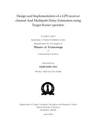
CISC Processor Design<br />
<strong>Implementation</strong> <strong>from</strong> <strong>Hardware</strong><br />
<strong>Flow</strong>charts<br />
Virendra Singh<br />
<strong>Indian</strong> <strong>Institute</strong> of Science<br />
Bangalore<br />
virendra@computer.org<br />
Computer<br />
Design<br />
Laboratory<br />
& Test<br />
Advance Computer Architecture
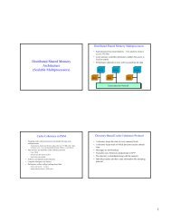
Processor Block Diagram<br />
Control<br />
Store<br />
Next<br />
State<br />
Control<br />
IB<br />
SB<br />
BC<br />
DB<br />
Instruction<br />
Decoder<br />
Control Word<br />
Register<br />
OP TY NA<br />
Control Fields (dynamic)<br />
Branch<br />
Control<br />
Control word<br />
Decoders<br />
Control Fields<br />
(Static)<br />
IRE<br />
Control lines<br />
Condition<br />
Codes<br />
IRF<br />
Datapath<br />
Advance Computer Architecture<br />
Computer<br />
Design<br />
Laboratory<br />
& Test
MIN Datapath<br />
th<br />
IRE<br />
IRF<br />
Internal A Bus<br />
DO<br />
AO PC T2 R0 R1 Rn T1 ALU<br />
k<br />
Internal B Bus<br />
DI<br />
External Address<br />
Bus (EAB)<br />
External Data<br />
Bus (EDB)<br />
Advance Computer Architecture<br />
Computer<br />
Design<br />
Laboratory<br />
& Test
<strong>Implementation</strong><br />
ti<br />
Each state in Level 2 flowchart corresponds to<br />
one control word<br />
Transformation of flowcharts into control store<br />
bit patterns<br />
‣ The task become bits in the control fields (OP)<br />
‣ The next state becomes in the control store<br />
address select (TY) and next address (NA)<br />
‣ The state ID becomes the location of the<br />
control word in the control store<br />
Advance Computer Architecture<br />
Computer<br />
Design<br />
Laboratory<br />
& Test
<strong>Implementation</strong><br />
ti<br />
Relationship between <strong>Flow</strong>charts and<br />
<strong>Hardware</strong><br />
<strong>Flow</strong>chart – compact and precise description of<br />
hardware requirements<br />
Stepts t for implementing microcoded d controller<br />
1. Execution Unit<br />
<br />
<br />
Develop concurrently<br />
Add things as and when needed<br />
Advance Computer Architecture<br />
Computer<br />
Design<br />
Laboratory<br />
& Test
<strong>Implementation</strong><br />
ti<br />
2. Instruction Decoders<br />
Translate an instruction bit pattern to the control<br />
store address for the execution sequence<br />
Two decoders are needed (for MIN)<br />
First, translates the instruction bit pattern into<br />
the control store address for the appropriate<br />
address mode sequence (provide IB)<br />
Second, translates the instruction bit pattern into<br />
control store address for the execution sequence<br />
(provide SB)<br />
Advance Computer Architecture<br />
Computer<br />
Design<br />
Laboratory<br />
& Test
<strong>Implementation</strong><br />
ti<br />
3. Control word format<br />
‣ Derived <strong>from</strong> flowcharts<br />
‣ HFC can tell required capability of control word<br />
precisely<br />
4. Control word decoders<br />
‣ Combine control word (dynamic) control fields,<br />
the IRE (static) control fields, and timing signals,<br />
to provide the gate control signals for all<br />
transfers in the Datapath and the Controller<br />
5. Controller block diagram<br />
Advance Computer Architecture<br />
Computer<br />
Design<br />
Laboratory<br />
& Test
<strong>Implementation</strong><br />
ti<br />
Design of flowchart<br />
‣ Made some assumptions (buses, registers..)<br />
‣ Collect the assumptions and implement<br />
Advance Computer Architecture<br />
Computer<br />
Design<br />
Laboratory<br />
& Test
MIN Datapath<br />
th<br />
IRE<br />
IRF<br />
Internal A Bus<br />
DO<br />
AO PC T2 R0 R1 Rn T1 ALU<br />
k<br />
Internal B Bus<br />
DI<br />
External Address<br />
Bus (EAB)<br />
External Data<br />
Bus (EDB)<br />
Advance Computer Architecture<br />
Computer<br />
Design<br />
Laboratory<br />
& Test
Instruction ti Decoders<br />
<br />
<br />
Two decoders<br />
First Decoder (IB decoder)<br />
‣ Points to the first control word in an address<br />
mode sequence (if there is one)<br />
‣ The last state t in any execution sequence is IB<br />
Second Decoder (SB decoder)<br />
‣ Points to the first control word of the execution<br />
sequence<br />
‣ The last sequence in addr. mode seq. is SB<br />
Advance Computer Architecture<br />
Computer<br />
Design<br />
Laboratory<br />
& Test
Instruction Execution<br />
Sequences<br />
Instruction<br />
Control Word<br />
Next control<br />
IB<br />
SB<br />
Sequence word Instruction Instruction<br />
address Decoder Decoder<br />
POP<br />
popr1<br />
popr2<br />
--- ---<br />
popr2<br />
brzz3<br />
brzz2<br />
brzz3<br />
brzz2<br />
---<br />
---<br />
---<br />
abdm1<br />
---<br />
---<br />
oprm1<br />
ADD<br />
RX(RY+d)@<br />
abdm1<br />
abdm2<br />
abdm3<br />
abdm4<br />
oprm1<br />
oprm2<br />
brzz3<br />
brzz2<br />
abdm2<br />
abdm3<br />
abdm4<br />
---<br />
oprm2<br />
brzz3<br />
brzz2<br />
---<br />
---<br />
---<br />
---<br />
---<br />
---<br />
---<br />
---<br />
oprr1<br />
Advance Computer Architecture<br />
oprm1<br />
oprm1<br />
oprm1<br />
oprm1<br />
---<br />
---<br />
---<br />
---<br />
Computer<br />
Design<br />
Laboratory<br />
& Test
Instruction Execution<br />
Sequences<br />
Instruction<br />
ti Control Word<br />
Next control<br />
IB<br />
SB<br />
Sequence word Instruction Instruction<br />
address Decoder Decoder<br />
SUB RX RY oprr1<br />
oprr2<br />
oprr2 brzz2<br />
brzz2 ---<br />
TEST RY@<br />
PUSH<br />
adrm1<br />
test1<br />
ldrm2<br />
---<br />
ldrm2<br />
---<br />
---<br />
---<br />
adrm1<br />
adrm1<br />
---<br />
push1<br />
---<br />
---<br />
test1<br />
test1<br />
---<br />
---<br />
Advance Computer Architecture<br />
Computer<br />
Design<br />
Laboratory<br />
& Test
IB Instruction Decoder<br />
IB Decoder<br />
Address<br />
Instruction(s) or<br />
Address Mode<br />
abdm1 (RY+d)@ Address mode<br />
adrm1<br />
RY@<br />
sequences<br />
brzz1 BZ Execution<br />
ldrr1<br />
LR<br />
sequences<br />
(Instructions<br />
strr1 STR without separate<br />
oprr1<br />
AR, SR, NR address mode<br />
popr1<br />
POP<br />
sequences)<br />
push1<br />
PUSH<br />
Advance Computer Architecture<br />
Computer<br />
Design<br />
Laboratory<br />
& Test
SB Instruction Decoder<br />
SB Decoder<br />
Address<br />
Instruction(s) or<br />
Address Mode<br />
ldrm1 L Execution sequences<br />
strm1 ST<br />
(Instructions with<br />
separate address<br />
oprm1 A, S, N<br />
mode sequences)<br />
test1 T<br />
Advance Computer Architecture<br />
Computer<br />
Design<br />
Laboratory<br />
& Test
Control Word Format<br />
<br />
Control words<br />
‣ Operation section (OP) is composed of the<br />
fields for Datapath control<br />
‣ Next state section, containing TY and NA,<br />
contains the field for state sequencer control<br />
‣ If two macro in the Datapath are never used at<br />
the same time, you might consider sharing the<br />
control field<br />
OP TY NA<br />
Advance Computer Architecture<br />
Computer<br />
Design<br />
Laboratory<br />
& Test
MIN Control Word<br />
Control Fields<br />
AO PC T2 Regs T1 ALU K DI DO IRE IRF ….<br />
MIN Execution Unit<br />
IRE<br />
IRF<br />
Internal A Bus<br />
DO<br />
AO PC T2 R0 R1 Rn T1 ALU<br />
Internal B Bus<br />
k<br />
DI<br />
(EAB)<br />
Advance Computer Architecture<br />
(EDB)<br />
Computer<br />
Design<br />
Laboratory<br />
& Test
Control Word Decoder<br />
How many bits each control needs?<br />
Procedure<br />
1. List uses of the macro<br />
2. Allocate bits<br />
3. Use a Karnaugh map to assign bit patterns<br />
Collect all the occurrences (PC, T2, RX …)<br />
Assign no. of bits to control fields<br />
Advance Computer Architecture<br />
Computer<br />
Design<br />
Laboratory<br />
& Test
Control Word Decoder<br />
PC Control<br />
‣ PC occurrences<br />
• pc → a<br />
• a → pc (only one occurrence – abdm2)<br />
• b → pc<br />
• none<br />
Advance Computer Architecture<br />
Computer<br />
Design<br />
Laboratory<br />
& Test
PC Control<br />
pcb<br />
0<br />
1<br />
pca<br />
0 1<br />
none<br />
b → pc<br />
pc → a<br />
x<br />
Internal A Bus<br />
pca<br />
PC<br />
pcb<br />
Internal nal B Bus<br />
Advance Computer Architecture<br />
Computer<br />
Design<br />
Laboratory<br />
& Test
Control Word Decoder<br />
T2 Control<br />
‣ T2 occurrences<br />
• t2 → a<br />
• t2 → b<br />
• a → t2 (only one occurrence – abdm4)<br />
• b → t2<br />
• None<br />
‣ Assign two bits (4 occurrences)<br />
Advance Computer Architecture<br />
Computer<br />
Design<br />
Laboratory<br />
& Test
T2 Control<br />
t2b<br />
0<br />
1<br />
t2a<br />
0 1<br />
none<br />
b → t2<br />
t2 → a<br />
t2 → b<br />
Internal A Bus<br />
a2a . t2b<br />
T2<br />
t2b . t2a<br />
a2a . t2b<br />
Internal nal B Bus<br />
Advance Computer Architecture<br />
Computer<br />
Design<br />
Laboratory<br />
& Test
Next State Logic<br />
Control<br />
Store<br />
Next<br />
State<br />
Control<br />
IB<br />
SB<br />
BC<br />
DB<br />
Instruction<br />
ti<br />
Decoders<br />
Control Word<br />
Register<br />
OP TY NA<br />
Control Fields (dynamic)<br />
Branch<br />
Control<br />
Conditional<br />
Code<br />
Z<br />
Advance Computer Architecture<br />
Computer<br />
Design<br />
Laboratory<br />
& Test
Control Word Decoder<br />
Register control<br />
‣ RX and RY occurrences<br />
ry → a<br />
b→ rx<br />
ry → b; b → rx<br />
rx → a<br />
rx → b; b → ry<br />
rx → a; ry → b<br />
b→ ry<br />
b → rx; a → ry<br />
rx → a; b → ry<br />
none<br />
Advance Computer Architecture<br />
Computer<br />
Design<br />
Laboratory<br />
& Test
Register Control<br />
Internal A Bus<br />
r0→a/ b→r0<br />
→r0<br />
r0→a<br />
MUX<br />
R0<br />
r0→b<br />
Internal B Bus<br />
Advance Computer Architecture<br />
Computer<br />
Design<br />
Laboratory<br />
& Test
Register Control<br />
Control word (<strong>from</strong> Control Store)<br />
AO PC T2 Regs T1 ……<br />
Instruction (<strong>from</strong> IRE)<br />
OP RX Mode RY<br />
Control Word register<br />
Control Field Decoder<br />
MUX<br />
n-to-2 n Decoder<br />
r→a r→b<br />
→r<br />
r0<br />
r1<br />
r2<br />
rn<br />
a→r/b→r<br />
Advance Computer Architecture<br />
Computer<br />
Design<br />
Laboratory<br />
& Test
Register Control<br />
Control word (<strong>from</strong> Control Store)<br />
AO PC T2 Regs T1 ……<br />
Control Word RX register<br />
Control Field Decoder<br />
Control Word RY register<br />
Control Field Decoder<br />
Instruction (<strong>from</strong> IRE)<br />
OP RX Mode RY<br />
b→rx<br />
rx→a<br />
rx→b<br />
x0<br />
→ry<br />
a→ry/b→ry<br />
ry→a<br />
ry→b<br />
n-to-2 n RX Decoder<br />
x1<br />
Advance Computer Architecture<br />
x2<br />
y0<br />
xn<br />
n-to-2 n RY Decoder<br />
y1<br />
y2<br />
Computer<br />
Design<br />
yn<br />
Laboratory<br />
& Test
Control Word Decoder<br />
Register control<br />
→ r0 = (b → rx).x0 + (→ ry). y0<br />
a→ r0 = (b → rx).x0 + ((a→ ry)/(b → ry)’). y0<br />
r0→ a = (rx → a).x0 + (ry→ a). y0<br />
r0→ b = (rx → b).x0 + (ry→ b). y0<br />
load r0<br />
load <strong>from</strong> A<br />
to A<br />
to B<br />
Advance Computer Architecture<br />
Computer<br />
Design<br />
Laboratory<br />
& Test
Control Word Decoder<br />
Control Word States<br />
ry → a<br />
b→ rx<br />
ry → b; b → rx<br />
rx → a<br />
rx → b; b → ry<br />
rx → a; ry → b<br />
b→ ry<br />
b → rx; a → ry<br />
rx → a; b → ry<br />
none<br />
Control Lines<br />
ry → a<br />
b → rx; → rx<br />
ry → b; → rx; b → rx<br />
rx → a<br />
rx → b; → ry; b → ry<br />
rx → a; ry → b<br />
b→ ry; → ry<br />
b → rx; → ry; a → ry; → ry<br />
rx → a; → ry; b → ry<br />
none<br />
Advance Computer Architecture<br />
Computer<br />
Design<br />
Laboratory<br />
& Test
Control Word Decoder<br />
Control Lines<br />
rx → a<br />
ry → a<br />
rx → b<br />
ry → b<br />
→ rx<br />
→ ry<br />
a → ry<br />
b → rx<br />
b → ry<br />
Advance Computer Architecture<br />
Computer<br />
Design<br />
Laboratory<br />
& Test
Register Control<br />
00<br />
01 11 10<br />
0 1 3 2<br />
00 none b→rx rx→a ry→a<br />
4 5 7 6<br />
01 b → ry<br />
rx → a rx → b<br />
b → ry b → ry<br />
11<br />
b → rx<br />
a → ry<br />
12 13 15 14<br />
8 9 11 10<br />
10 b → rx rx → a<br />
ry → b ry → b<br />
b → rx<br />
→ rx<br />
rx → a<br />
Advance Computer Architecture<br />
b → ry<br />
→ ry<br />
a → ry<br />
Computer<br />
Design<br />
Laboratory<br />
& Test
Control Word Decoder<br />
Control Word States<br />
Control Bit Assignment<br />
none<br />
b → rx<br />
‣ 0000<br />
‣ 0001<br />
ry → a<br />
‣ 0010<br />
rx → a<br />
‣ 0011<br />
b → ry<br />
‣ 0100<br />
rx → b; b → ry<br />
‣ 0110<br />
rx → a; b → ry<br />
‣ 0111<br />
ry → b; b → rx<br />
‣ 1001<br />
rx → a; ry → b<br />
‣ 1011<br />
b → rx; a → ry ‣ 1101<br />
Advance Computer Architecture<br />
Computer<br />
Design<br />
Laboratory<br />
& Test
Control Word Decoder<br />
Control Lines<br />
rx → a<br />
ry → a<br />
rx → b<br />
ry → b<br />
→ rx<br />
→ ry<br />
A → ry<br />
b → rx<br />
b → ry<br />
Decoder Patterns<br />
‣ xx11<br />
‣ 0010<br />
‣ 0110<br />
‣ 10xx<br />
‣ xx01<br />
‣ x1xx<br />
‣ 11xx<br />
‣ xx01<br />
‣ 01xx<br />
Advance Computer Architecture<br />
Computer<br />
Design<br />
Laboratory<br />
& Test
Control word (<strong>from</strong> Control Store)<br />
Register Control<br />
Instruction (<strong>from</strong> IRE)<br />
AO PC T2 Regs T1 ……<br />
OP RX Mode RY<br />
MUX<br />
n-to-2 n A Decoder<br />
Control Word RX register<br />
Control Field Decoder<br />
a→rr<br />
rr→a<br />
r0<br />
r1 r2<br />
rn<br />
MUX<br />
Control Word RY register b→rr<br />
Control Field Decoder<br />
rr→b<br />
Advance Computer Architecture<br />
n-to-2 n B Decoder<br />
r0 r1 r2<br />
rn<br />
Computer<br />
Design<br />
Laboratory<br />
& Test
ALU Control<br />
Control Word state<br />
a→ alu; +1 → alu; add-n; alu→ t1<br />
a→ alu; b → alu; add-n; alu→ t1<br />
a→ alu; 0 → alu; add-s; alu→ t1<br />
a→ alu; b → alu; op-s; alu→ t1<br />
a→ alu; -1→ alu; add-n; alu→ t1<br />
Control Lines<br />
‣ load t1<br />
‣ load ccr<br />
‣ add/op select<br />
‣ alu-b input select<br />
Advance Computer Architecture<br />
Computer<br />
Design<br />
Laboratory<br />
& Test
ALU Control<br />
CCR<br />
Select<br />
MUX1<br />
IRE<br />
load ccr<br />
ADD<br />
T1<br />
load t1<br />
FTN<br />
A<br />
ALU<br />
B<br />
MUX2<br />
Internal Bus A<br />
+1<br />
0<br />
-1<br />
Select<br />
Internal Bus B<br />
Advance Computer Architecture<br />
Computer<br />
Design<br />
Laboratory<br />
& Test
ALU Control<br />
0<br />
00 01 11 10 1<br />
0 1 3 2<br />
none<br />
4 5 7 6<br />
b→alu<br />
add-n<br />
1 0 → alu +1 → alu -1 → alu b → alu<br />
add-s add-n add-n op-s<br />
Karnaugh map for ALU control assignment<br />
Advance Computer Architecture<br />
Computer<br />
Design<br />
Laboratory<br />
& Test
ALU Control<br />
Control Word state<br />
a→ alu; +1 → alu; add-n; alu→ t1<br />
a→ alu; b → alu; add-n; alu→ t1<br />
a→ alu; 0 → alu; add-s; alu→ t1<br />
a→ alu; b → alu; op-s; alu→ t1<br />
a→ alu; -1→ alu; add-n; alu→ t1<br />
Control Field bit<br />
assignment<br />
‣ 101<br />
‣ 010<br />
‣ 100<br />
‣ 110<br />
‣ 111<br />
none ‣ 000<br />
Advance Computer Architecture<br />
Computer<br />
Design<br />
Laboratory<br />
& Test
ALU Control<br />
Control Lines<br />
• load t1<br />
• load ccr<br />
• add/op select<br />
• alu-b input select<br />
Decoder Patterns<br />
‣ xxx | 000 (all except 000)<br />
‣ 1x0<br />
‣ 110<br />
‣ x10<br />
Advance Computer Architecture<br />
Computer<br />
Design<br />
Laboratory<br />
& Test
Next State Logic<br />
Control<br />
Store<br />
Next<br />
State<br />
Control<br />
IB<br />
SB<br />
BC<br />
DB<br />
Instruction<br />
ti<br />
Decoders<br />
Control Word<br />
Register<br />
OP TY NA<br />
Control Fields (dynamic)<br />
Branch<br />
Control<br />
Conditional<br />
Code<br />
Z<br />
Advance Computer Architecture<br />
Computer<br />
Design<br />
Laboratory<br />
& Test
Performance<br />
Enhancement<br />
1. More operations<br />
2. Overlap Fetch, Decode, and execution<br />
3. Balance the operations in a state<br />
Advance Computer Architecture<br />
Computer<br />
Design<br />
Laboratory<br />
& Test
Thank You<br />
Advance Computer Architecture<br />
Computer<br />
Design<br />
Laboratory<br />
& Test