
Create successful ePaper yourself
Turn your PDF publications into a flip-book with our unique Google optimized e-Paper software.
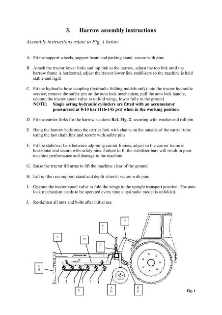
3. Harrow assembly instructions<br />
Assembly instructions relate to Fig. 1 below<br />
A. Fit the support wheels, support beam and parking stand, secure with pins<br />
B. Attach the tractor lower links and top link to the <strong>harrow</strong>, adjust the top link until the<br />
<strong>harrow</strong> frame is horizontal, adjust the tractor lower link stabilisers so the machine is held<br />
stable and rigid<br />
C. Fit the hydraulic hose coupling (hydraulic folding models only) into the tractor hydraulic<br />
service, remove the safety pin on the auto lock mechanism, pull the auto lock handle,<br />
operate the tractor spool valve to unfold wings, lower fully to the ground<br />
NOTE: Single acting hydraulic cylinders are fitted with an accumulator<br />
pressurised at 8-10 bar (116-145 psi) when in the working position<br />
D. Fit the carrier forks for the <strong>harrow</strong> sections Ref. Fig. 2, securing with washer and roll pin.<br />
E. Hang the <strong>harrow</strong> beds onto the carrier fork with chains on the outside of the carrier tube<br />
using the last chain link and secure with safety pins<br />
F. Fit the stabiliser bars between adjoining carrier frames, adjust so the carrier frame is<br />
horizontal and secure with safety pins. Failure to fit the stabiliser bars will result in poor<br />
machine performance and damage to the machine<br />
G. Raise the tractor lift arms to lift the machine clear of the ground<br />
H. Lift up the rear support stand and depth wheels, secure with pins<br />
I. Operate the tractor spool valve to fold the wings to the upright transport position. The auto<br />
lock mechanism needs to be operated every time a hydraulic model is unfolded.<br />
J. Re-tighten all nuts and bolts after initial use<br />
C<br />
I<br />
B<br />
A<br />
D<br />
C<br />
I<br />
A<br />
H<br />
E<br />
A<br />
B<br />
G<br />
H Fig. 1