Power Factor Correction Demystified - Energie & Technik
Power Factor Correction Demystified - Energie & Technik
Power Factor Correction Demystified - Energie & Technik

Create successful ePaper yourself
Turn your PDF publications into a flip-book with our unique Google optimized e-Paper software.
www.microchip.com<br />
Component sizes would be small at these switching frequencies. The current controller<br />
produces a duty-cycle value to drive the gate of the PFC MOSFET. A proportional-integral<br />
controller is used to achieve the current-error compensation.<br />
Voltage Loop<br />
The outer loop in the control block forms the voltage loop. The input to the voltage loop is the<br />
reference DC voltage and the sensed output voltage. The voltage-error compensator is<br />
designed to produce a control output such that the DC output voltage remains constant at the<br />
reference value, regardless of variations in the load current and changes in the supply<br />
voltage. The voltage controller produces a control signal, which determines the reference<br />
current for the inner current loop. The voltage-loop bandwidth is chosen to be 10 Hz. This is<br />
selected to be well below the input frequency of 100 Hz or 120 Hz, so that the output voltage<br />
remains constant and still maintains the necessary shape of the inductor current, without<br />
distorting it. A proportional-integral controller is used to achieve the voltage-error<br />
compensation.<br />
Voltage Feed-Forward Compensator<br />
If the voltage decreases, the product of V AC and V PI , which determines current reference,<br />
also proportionally decreases. However, to maintain a constant output power at a reduced<br />
input voltage, the current reference must increase. The purpose of having an input voltage<br />
feed-forward term is to maintain the output power constant, as determined by the load,<br />
regardless of sudden variations in the input-line voltage. This compensator is implemented<br />
digitally by calculating the average value of the input-line voltage and using the result as a<br />
divider for the current reference. This resulting signal acts as the input to the inner current<br />
loop.<br />
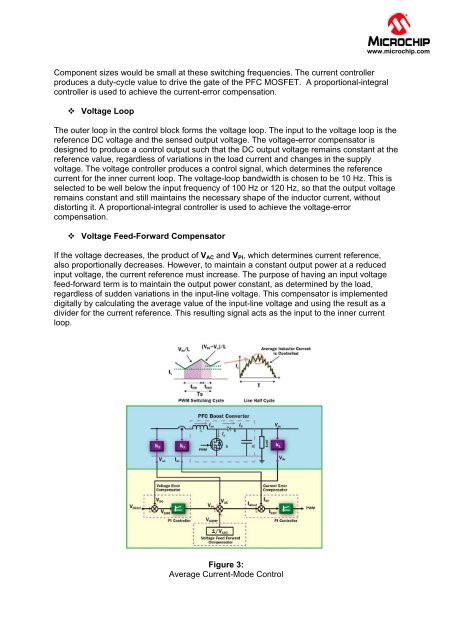
Figure 3:<br />
Average Current-Mode Control